California Code of Regulations
Title 24, Part 2, Volume 1 of 2
California Building
Standards Commission
Based on the 2009 International Building Code®
California Code of Regulations
Title 24, Part 2, Volume 1 of 2
California Building
Standards Commission
Based on the 2009 International Building Code®

EFFECTIVE DATE: January 1, 2011
(For Errata and supplements, See History Note Appendix)
Public Domain: U.S. Court of Appeals, Fifth Circuit, 99-40632
2010 California Building Code
California Code of Regulations, Title 24, Volume 1 of Part 2
First Printing: June 2010
ISBN 978-1-58001-974-3
Copyright © 2010
Held by
California Building Standards Commission
2525 Natomas Park Drive, Suite 130
Sacramento, CA 95833-2936
ALL RIGHTS RESERVED. This 2010 California Building Code contains substantial copyrighted material from the 2009 International Building Code, Second Printing, which is a copyrighted work owned by the International Code Council, Inc. Without advance written permission from the copyright owner, no part of this book may be reproduced, distributed or transmitted in any form or by any means, including, without limitation, electronic, optical or mechanical means (by way of example and not limitation, photocopying, or recording by or in an information storage retrieval system). For information on permission to copy material exceeding fair use, please contact: Publications, 4051 West Flossmoor Road, Country Club Hills, IL 60478. Phone 1-888-ICC-SAFE (422-7233).
Trademarks: “International Code Council,” the “International Code Council” logo and the “International Building Code” are trade marks of the International Code Council, Inc.
PRINTED IN THE U.S.A.
This document is Part 2 of 12 parts of the official triennial compilation and publication of the adoptions, amendments and repeal of administrative regulations to California Code of Regulations, Title 24, also referred to as the California Building Standards Code. This Part is known as the California Building Code.
The California Building Standards Code is published in its entirety every three years by order of the California legislature, with supplements published in intervening years. The California legislature delegated authority to various state agencies, boards, commissions and departments to create building regulations to implement the State’s statutes. These building regulations or standards, have the same force of law, and take effect 180 days after their publication unless otherwise stipulated. The California Building Standards Code applies to occupancies in the State of California as annotated.
A city, county or city and county may establish more restrictive building standards reasonably necessary because of local climatic, geological or topographical conditions. Findings of the local condition(s) and the adopted local building standard(s) must be filed with the California Building Standards Commission to become effective and may not be effective sooner than the effective date of this edition of California Building Standards Code. Local building standards that were adopted and applicable to previous editions of the California Building Standards Code do not apply to this edition without appropriate adoption and the required filing.
Should you find publication (e.g., typographical) errors or inconsistencies in this code or wish to offer comments toward improving its format, please address your comments to:
California Building Standards Commission
2525 Natomas Park Drive, Suite 130
Sacramento, CA 95833-2936
Phone: (916) 263-0916
Fax: (916) 263-0959
Web Page: www.bsc.ca.gov
The 2010 California Building Standards Code (Code) was developed through the outstanding collaborative efforts of the Department of Housing and Community Development, the Division of State Architect, the Office of the State Fire Marshal, the Office of Statewide Health Planning and Development, the California Energy Commission, and the Building Standards Commission (Commission).
This collaborative effort included the assistance of the Commission’s Code Advisory Committees and many other volunteers that worked tirelessly to assist the Commission in the production of this Code.
Governor Arnold Schwarzenegger
Members of the Building Standards Commission
Acting Secretary Tom Sheehy – Chair
Isam Hasenin – Vice-Chair
James Barthman
Craig Daley
Susan Dowty
Tony Hoffman
Christina Jamison
Stephen Jensen
Michael Paravagna
Richard Sawhill
Steven Winkel
David Walls – Executive Director
Thomas Morrison – Deputy Executive Director
For questions on California state agency amendments; please refer to the contact list on the following page.
iiiCalifornia Agency Information Contact List
| California Energy Commission | |
| Energy Hotline | (800) 772-3300 |
| or (916) 654-5106 | |
| Building Efficiency Standards | |
| Appliance Efficiency Standards | |
| Compliance Manual/Forms | |
| California State Lands Commission | |
| Marine Oil Terminals | (562) 499-6317 |
| California State Library | |
| Resources and Information | (916) 654-0261 |
| Government Publication Section | (916) 654-0069 |
| Corrections Standards Authority | |
| Local Adult Jail Standards | (916) 324-1914 |
| Local Juvenile Facility Standards | (916) 324-1914 |
| Department of Consumer Affairs–Acupuncture Board | |
| Office Standards | (916) 445-3021 |
| Department of Consumer Affairs–Board of Pharmacy | |
| Pharmacy Standards | (916) 574-7900 |
| Department of Consumer Affairs–Bureau of Barbering And Cosmetology | |
| Barber and Beauty Shop and College Standards | (916) 574-7570 |
| Structural Standards | (800) 952-5210 |
| Department of Consumer Affairs–Bureau of Home Furnishings and Thermal Insulation | |
| Insulation Testing Standards | (916) 574-2041 |
| Department of Consumer Affairs–Structural Pest Control Board | |
| Structural Standards | (800) 737-8188 |
| (916) 561-8708 | |
| Department of Consumer Affairs–Veterinary Medical Board | |
| Veterinary Hospital Standard | (916) 263-2610 |
| Department of Food and Agriculture | |
| Meat and Poultry Packing Plant Standards | (916) 654-1447 |
| Dairy Standards | (916) 654-1447 |
| Department of Public Health | |
| Organized Camps Standards | (916) 449-5661 |
| Public Swimming Pools Standards | (916) 449-5693 |
| Asbestos Standards | (510) 620-2874 |
| Department of Housing and Community Development | |
| Residential–Hotels, Motels, Apartments, Single-Family Dwellings | (916) 445-9471 |
| Permanent Structures in Mobilehome and Special Occupancy Parks | (916) 445-9471 |
| Factory-Built Housing, Manufactured Housing and Commercial Modular | (916) 445-3338 |
| Mobilehomes–Permits and Inspections Northern Region | (916) 225-2501 |
| Southern Region | (951) 782-4420 |
| Employee Housing Standards | (916) 445-9471 |
| Department of Water Resources | |
| Gray Water Installations Standards | (916) 651-9667 |
| Division of the State Architect–Access Compliance | |
| Access Compliance Standards | (916) 445-8100 |
| Division of the State Architect–Structural Safety | |
| Public Schools Standards | (916) 445-8100 |
| Essential Services Building Standards | (916) 445-8100 |
| Community College Standards | (916) 445-8100 |
| Division of the State Architect–State Historical Building Safety Board | |
| Alternative Building Standards | (916) 445-8100 |
| Office of Statewide Health Planning and Development | |
| Hospital Standards | (916) 440-8409 |
| Skilled Nursing Facility Standards | (916) 440-8409 |
| Clinic Standards | (916) 440-8409 |
| Permits | (916) 440-8409 |
| Office of the State Fire Marshal | |
| Code Development and Analysis | (916) 445-8200 |
| Fire Safety Standards | (916) 445-8200 |
| Fireplace Standards | (916) 445-8200 |
| Day-Care Centers Standards | (916) 445-8200 |
| Exit Standards | (916) 445-8200 |
Distilling the code review process down to a methodical, sequential list of considerations is generally problematic. In many cases, related provisions from various chapters of the code must be considered simultaneously, or reconsidered later in the process to arrive at the correct classification or determination. Any number of acceptable alternatives may exist for construction of the building and its specific features. Each choice provided by the code must be evaluated for its specific impact on other aspects of the building's analysis. With a basic understanding of the interrelationship of the various chapters, the practiced code user will make an initial assessment of the building as a first step of the code review process. The following outline may be helpful as a guide for the effective use of the IBC, with the understanding that final resolution of each step is often dependant on subsequent steps.
The following process begins with a brief discussion of the key administrative areas of the code. The process addressing technical provisions is divided into two distinct areas of analysis, the nonstructural provisions of the IBC and the structural provisions. Although reference is not made to all provisions set forth in the IBC, the process is intended to be representative of an approach to using the IBC in an effective manner.
Administrative Provisions
Prior to any analysis based on the technical provisions of the IBC, it is important that the fundamental administrative aspects of the code be reviewed. It is critical that the basis of technical decisions be consistent with the approach established in IBC Chapter 1, including:
Nonstructural Provisions
| Sec. 303 | Group A |
| Sec. 304 | Group B |
| Sec. 305 | Group E |
| Sec. 306 | Group F |
| Sec. 307 | Group H |
| Sec. 308 | Group I |
| Sec. 309 | Group M |
| Sec. 310 | Group R |
| Sec. 311 | Group S |
| Sec. 312 | Group U |
| Sec. 602 | Type of construction based on materials of construction |
| Table 601 | Type of construction based on fire rating of the building elements |
| Sec. 603 | Combustible materials in Type I and II buildings |
| Sec. 504.2 | Story and height increase (reduced type of construction) |
| Sec. 506.3 | Allowable area increase (reduced type of construction) |
| Sec. 507.3 | Unlimited area building (reduced type of construction) |
| Sec. 1018.1 | Elimination of corridor fire-resistance rating |
| Sec. 506 | Single-occupancy building |
| Sec. 508.2 | Multi-occupancy w/accessory occupancies |
| Sec. 508.3 | Multi-occupancy building w/nonseparated occupancies |
| Sec. 508.4 | Multi-occupancy building w/separated occupancies |
| Sec. 706.1 | Use of fire walls |
| Sec. 402 | Covered mall buildings |
| Sec. 403 | High-rise buildings |
| Sec. 404 | Atriums |
| Sec. 405 | Underground buildings |
| Sec. 406 | Motor-vehicle-related occupancies |
| Sec. 407 | Group I-2 occupancies |
| Sec. 408 | Group I-3 occupancies |
| Sec. 411 | Special amusement buildings |
| Sec. 412 | Aircraft-related occupancies |
| Sec. 415 | Group H occupancies |
| Sec. 419 | Live/work units |
| Sec. 420 | Groups I-1, R-1, R-2 and R-3 |
| Sec. 422 | Ambulatory health care facilities |
| Sec. 704 | Structural members |
| Sec. 707 | Fire barriers |
| Sec. 709 | Fire partitions |
| Sec. 710 | Smoke barriers |
| Sec. 711 | Smoke partitions |
| Sec. 712 | Horizontal assemblies |
| Sec. 708 | Shaft enclosures |
| Sec. 713 | Penetrations |
| Sec. 714 | Joint systems |
| Sec. 715 | Opening protectives |
| Sec. 716 | Ducts and air transfer openings |
| Sec. 1005.1 | Egress width and distribution |
| Sec. 1006.3 | Emergency lighting |
| Sec. 1007 | Accessible means of egress |
| Sec. 1008.1.2 | Door swing |
| Sec. 1008.1.9 | Door operations |
| Sec. 1008.1.10 | Panic hardware |
| Sec. 1009.1 | Stairway width |
| Sec. 1009.4 | Stairway treads and risers |
| Sec. 1011 | Exit signs |
| Sec. 1012 | Stairway and ramp handrails |
| Sec. 1013 | Guards |
| Sec. 1014.2 | Egress through intervening spaces |
| Sec. 1014.3 | Common path of egress travel |
| Sec. 1015.1 | Number of exit or exit access doorways |
| Sec. 1015.2 | Egress separation |
| Sec. 1016.1 | Travel distance |
| Sec. 1018.1 | Corridor construction |
| Sec. 1021 | Number of exits |
| Sec. 1022 | Vertical exit enclosures |
| Sec. 1023 | Exit passageways |
| Sec. 1025 | Horizontal exits |
| Sec. 1026 | Exterior exit stairways |
| Sec. 1027 | Exit discharge |
| Sec. 1028 | Egress from assembly occupancies |
| Sec. 410 | Stages and platforms |
| Sec. 413 | Combustible storage |
| Sec. 414 | Hazardous materials |
| Sec. 416 | Application of flammable finishes |
Structural Provisions
General Requirements
The 2009 IBC reference the national load standard, Minimum Design Loads for Buildings and Other Structures (ASCE/SEI 7—O5) with Supplement Number 2.
Determine the applicable design loads that the building structure is expected to be subjected to. Code prescribed loads are given in Chapter 16 and the referenced standard, ASCE/SEI 7. The code prescribed minimum live loads are given in IBC Table 1607.1.
The various code prescribed loads are probabilistic in nature. Environmental loads, such as flood, rain, snow, seismic and wind vary based on the location of the building site. The following table gives the IBC section and ASCE/SEI 7 chapter for various types of load.
| REFERENCED IBC SECTIONS AND ASCE/SEI 7 CHAPTERS FOR LOADS | ||
|---|---|---|
| TYPE OF LOAD | IBC SECTION | ASCE/SEI 7 CHAPTER |
| Dead loads | Section 1606 | Chapter 3 |
| Live loads | Section 1607, Table 1607.1 | Chapter 4 |
| Snow loads | Section 1608 | Chapter 7 |
| Wind loads | Section 1609 | Chapter 6 |
| Soil lateral loads | Section 1610 | Chapter 3 |
| Rain loads | Section 1611 | Chapter 8 |
| Flood loads | Section 1612 | Chapter 51 |
| Earthquake loads | Section 1613 | Chapter 11-22 |
| 1 Section 1612 references ASCE 24 which references Chapter 5 of ASCE/SEI 7 | ||
The structural design begins with the selection of the type of structural materials to be used to support the building. Structural framing systems are constructed of concrete, masonry, steel or wood. Some miscellaneous or specialty structures and components, such as awnings, canopies and cladding, are often constructed of aluminum.
The design of various structural materials is covered in specific material chapters in the code which in turn reference design standards for the type of material involved. The referenced standards in the 2009 IBC for the structural materials are shown in the following table:
| STRUCTURAL DESIGN STANDARDS FOR STRUCTURAL MATERIALS1 | ||
|---|---|---|
| MATERIAL | IBC/CBC CHAPTER | REFERENCED STANDARD |
| Concrete | 19 | ACI 318—08 Building Code Requirements for Structural Concrete |
| Aluminum | 20 | ADM 1—05 Aluminum Design Manual |
| Masonry | 21 | TMS 402-08/ACI 530-08/ASCE 5-08 Building Code Requirements and Specification for Masonry Structures (MSJC Code) |
| Steel | 22 | AISC 360—05 Specification for Structural Steel Buildings AISC 341—05 Seismic Provisions for Structural Steel Buildings, including Supplement No. 1 dated 2006 AISI S100—2007 North American Specification for the Design of Cold-Formed Steel Structural Members |
| Wood | 23 | AF&PA NDS—05 National Design Specification (NDS) for Wood Construction with 2005 Supplement AF&PA SDPWS—08 Special Design Provisions for Wind and Seismic |
| 1. The above table shows the main structural design standards for these structural materials. For a complete list of referenced standards, see IBC Chapter 35. | ||
Once the applicable loads are determined, the structural system of the building must be analyzed to determine the effects of the governing gravity and lateral loads that act on the structure. The structural system of a typical building consists of the roof and floor systems, walls, beams and columns, and the foundation. From the structural analysis, the next step is to design the structural members, elements and systems to provide the minimum level of resistance in accordance with the various load combinations prescribed in Section 1605.
Once the structural elements and systems are designed, the next step is to detail the load transfer connections to provide a complete load path from the point of origin to the resisting element. In general, the ultimate resisting element of buildings and structures is the foundation and supporting ground. The final step is to prepare a complete set of construction documents as required by Sections 107 and 1603. Construction documents are defined in Section 202 as "Written, graphic and pictorial documents prepared or assembled for describing the design, location and physical characteristics of the elements of a project necessary for obtaining a building permit." In general, construction documents consist of plans, specifications and calculations.
Section 1603.1 requires construction documents to show the size, section and relative locations of structural members with floor levels, column centers and offsets dimensioned. Design loads required by Sections 1603.1.1 through 1603.1.9 must be indicated on the construction documents. If complete construction documents consisting of plans, specifications and calculations are provided, the items listed in Sections 1603.1.1 through 1603.9 are generally included.
xThe exception permits construction documents for buildings constructed in accordance with the conventional light-frame construction provisions of Section 2308 need only indicate the following:
Floor and roof live loads
Ground snow load, Pg.
Basic (3-second gust) wind speed (mph) and wind exposure category.
Seismic design category and site class.
Flood design data where sited in flood hazard areas
Design load-bearing values of soils.
General Requirements
Determine the occupancy category of the building based on Table 1604.5.
Where a structure is occupied by two or more occupancies that are not the same occupancy category, the building must be classified in the highest occupancy category corresponding to the various occupancies.
Where structures have two or more portions that are structurally separated, each separate portion should be separately classified.
Where a separated portion of a structure provides required access or egress from another portion of the building with a higher occupancy category, both portions of the building must be assigned the higher occupancy category.
Where a separated portion of a structure shares life safety components with another portion of the building with a higher occupancy category, both portions of the building must be assigned the higher occupancy category.
Determine uniformly distributed and concentrated floor live load for the floor areas of the building in accordance with Section 1603.1.1 and Table 1607.1.
Floor live load reduction in accordance with Section 1607.9 should be indicated for each type of live load that is reduced.
Determine the roof live load for roof areas in accordance with Section 1607.11.
Roof live load reduction in accordance with Section 1607.11.2 should be indicated for roof live loads that are reduced.
Determine the ground snow load, Pg, based on the location of the building site in accordance with Figure 1608.2 for the contiguous United States and Table 1608.2 for Alaska.
In areas where the ground snow load, Pg, exceeds 10 psf, the following information should be determined:
Determine the following information related to wind loads in accordance with Section 1603.1.4:
Determine the following information related to seismic loads regardless of whether seismic loads govern the design of the lateral-force-resisting system of the building:
The design load bearing values of soils shall be shown on the construction documents in accordance with Section 1603.1.6.
Determine any special loads that are applicable to the design of the building, structure or portions thereof along with the specific section of the code that addresses the special loading condition in accordance with Section 1603.1.8.
Buildings and other structures and portions thereof are required to be designed to resist the load combinations specified in Section 1605.2 or 1605.3 and Chapters 18 through 23, and the special seismic load combinations with overstrength as required by Section 1605.1 and ASCE/SEI 7.
Lateral-force-resisting systems are required to conform to the seismic detailing requirements of the code and ASCE/SEI 7 (excluding Chapter 14 and Appendix 11A) even when wind load effects are greater than seismic load effects. See Section 1604.10.
Structural systems and members shall be designed to have adequate stiffiness to limit deflections and lateral drift. The deflection of structural members shall not exceed the more restrictive of the limitations of Sections 1604.3.2 through 1604.3.6 or that permitted by Table 1604.3. Structural systems shall be designed to have adequate stiffness to limit deformation and lateral drift due to earthquake loading in accordance with Section 12.12.1 of ASCE/SEI 7.
A foundation system must be designed that provides adequate support for gravity and lateral loads. Walls of buildings of conventional light frame construction, as defined in Section 202, are permitted to be supported by footings constructed in accordance with Table 1809.7. Otherwise, the foundation system must be designed in accordance with other provisions of Chapter 18. The following table gives a summary of applicable sections for foundation systems.
| FOUNDATION REQUIREMENTS | |
|---|---|
| SUBJECT | IBC SECTION |
| Presumptive load-bearing values of soils | 1806, Table 1806.2 |
| Foundation walls, retaining walls and embedded posts & poles | 1807 |
| General requirements for foundations | 1808 |
| Minimum concrete specified concrete strength | Table 1808.8.1 |
| Minimum concrete cover | Table 1808.8.2 |
| Shallow foundations (footings) | 1809 |
| Prescriptive footings for light frame walls | Table 1809.7 |
| Deep foundations | 1810 |
A geotechnical investigation is required where required by Section 1803.2 unless the building official determines that a soils investigation is not required in accordance with the exception. A geotechnical investigation is required for buildings assigned to Seismic Design Categories C, D, E and F in accordance with Sections 1803.5.11 and 1803.5.12.
Requirements for excavation, grading and fill related to foundation construction are covered in Section 1804. General requirements for site grading are covered in Appendix J.
Where required by Section 1612.5, buildings located in flood hazard areas as established in Section 1612.3 are required to provide documentation that includes the following information regardless of whether flood loads govern the design of the building:
Where special inspection, special inspection for seismic resistance, or structural testing for seismic resistance is required by Section 1704, 1707 or 1708, the registered design professional in responsible charge is required to prepare a statement of special inspections in accordance with Section 1705. The statement of special inspections must be submitted by the permit applicant as a condition of permit issuance in accordance with Section 106.1.
A statement of special inspections is not required for structures designed and constructed in accordance with the conventional construction provisions of Section 2308 unless specific components in the structure require special inspection.
The statement of special inspections is permitted to be prepared by a qualified person approved by the building official for construction not designed by a registered design professional.
| SPECIAL INSPECTION REQUIREMENTS | ||
|---|---|---|
| TYPE OF SPECIAL INSPECTION | APPLICABLE SECTION | REQUIRED VERIFICATION AND INSPECTION |
| Steel construction | 1704.3 | Table 1704.3 |
| Concrete construction | 1704.4 | Table 1704.4 |
| Masonry construction | ||
| Level 1 | 1704.5 | Table 1704.5.1 |
| Level 2 | Table 1704.5.3 | |
| Wood construction | 1704.6 | — |
| Soils | 1704.7 | Table 1704.7 |
| Driven deep foundations | 1704.8 | Table 1704.8 |
| Cast in place deep foundations | 1704.9 | Table 1704.9 |
| Helical pile foundations | 1704.10 | — |
| Vertical masonry foundations | 1704.11 | — |
| 1704.5 | ||
| Sprayed fire resistant materials | 1704.12 | — |
| Mastic and intumescent fire resistive coatings | 1704.13 | — |
| Exterior insulation and finish (EIFS) systems | 1704.14 | — |
| Special cases | 1704.15 | — |
| Smoke control systems | 1704.16 | — |
| Where required by the provisions of Section 1709.2 or 1709.3, the owner shall employ a registered design professional to perform structural observations as defined in Section 1702. At the conclusion of the work included in the permit, the structural observer shall submit a written statement to the building official that identifies any reported deficiencies that have not been resolved. | ||
Section 1706.1 requires special inspections for wind requirements based on wind speed and exposure category as prescribed in Section 1706.2 through 1706.4, unless exempted by the exceptions to Section 1704.1.
Section 1707.1 requires special inspections for seismic resistance based on seismic design category as prescribed in Sections 1707.2 through 1707.9, unless exempted by the exceptions of Section 1704.1 or 1705.3.
Section 1708.1 requires specific testing and qualification for seismic resistance as prescribed in Sections 1708.2 through 1708.5, unless exempted from special inspections by the exceptions of Section 1704.1 and 1705.3:
Where required by the provisions of Section 1710.2 or 1710.3 the owner is required to employ a registered design professional to perform structural observations as defined in Section 1702. Section 1710.2 requires structural observations for seismic resistance for certain structures assigned to Seismic Design Category D, E or F; Section 1710.3 requires structural observations for wind requirements for certain structures sited where the wind speed exceeds 110 mph.
At the conclusion of the work included in the permit, the structural observer is required to submit a written statement to the building official that identifies any reported deficiencies that have not been resolved.
Prior to the commencement of observations, the structural observer is required to submit a written statement to the building official identifying the structural observations.
At the conclusion of the work included in the permit, the structural observer is required to submit a written statement to the building official indicating what site visits have been made, identifies any deficiencies that have not been resolved.
Section 1709 requires each contractor responsible for the construction of a main wind-or seismic-force-resisting system, designated seismic system or a wind- or seismic-resisting component listed in the statement of special inspections is required to submit a written statement of responsibility to the building official and the owner prior to the commencement of work on the system or component. (The term “designated seismic system” is defined in Section 1702 and Section 11.2 of ASCE/SEI 7). The contractor’s statement of responsibility is required to acknowledge awareness of the special requirements contained in the statement of special inspections.
Construction of foundations or other part of a building is permitted before the construction documents for the whole building or structure have been submitted, provided adequate information has been filed. The holder of such permit for the foundation or other part of a building proceeds at their own risk and without assurance that a permit for the entire structure will be granted.
Work must be constructed in accordance with the approved construction documents and any changes made during construction that are not in compliance with the approved construction documents must be resubmitted for approval as amended construction documents.
Deferred submittals are items that are not submitted at the time of permit application and must have the prior approval of the building official in accordance with Section 107.3.4.2. The registered design professional in responsible charge is required to list the deferred submittals on the construction documents for review by the building official. Documents for deferred submittal items must be reviewed by the registered design professional in responsible charge who will forward them to the building official with a notation indicating the they have been reviewed and are in general conformance with the design of the building.
To distinguish between model code language and the incorporated California amendments, including exclusive California standards, California amendments will appear in italics.
[BSC] This symbol within a section identifies which State agency(s), by its “acronym,”has amended a section of the model code.
| Legend of Acronyms of Adopting State Agencies | |
|---|---|
| BSC | California Building Standards Commission |
| SFM | Office of the State Fire Marshal |
| HCD | Department of Housing and Community Development |
| DSA-AC | Division of the State Architect-Access Compliance |
| DSA-SS | Division of the State Architect-Structural Safety |
| DSA-SS/CC | Division of the State Architect-Structural Safety/Community Colleges |
| OSHPD | Office of Statewide Health Planning and Development |
| CSA | Corrections Standards Authority |
| DPH | Department of Public Health |
| AGR | Department of Food and Agriculture |
| CEC | California Energy Commission |
| CA | Department of Consumer Affairs: Board of Barbering and Cosmetology Board of Examiners in Veterinary Medicine Board of Pharmacy Acupuncture Board Bureau of Home Furnishings Structural Pest Control Board |
| SL | State Librarian |
| SLC | State Lands Commission |
| DWR | Department of Water Resources |
Symbols in the margins indicate the status of code changes as follows:
This symbol indicates that a change has been made to a California amendment.
This symbol indicates California deletion of California language.
xv xviFormat of the California Matrix Adoption Tables
The matrix adoption tables, which follow, show the user which state agencies have adopted and/or amended given sections of the model code. The building application determines which state agency’s adoptions apply. See Section’s 102 through 114 for building applications and enforcement responsibilities.
Agencies are grouped together, based on either local or state enforcement responsibilities. For example, regulations from SFM are enforced both at the state and local levels; therefore, SFM is listed twice in each adoption table indicating state enforcement responsibilities and local enforcement responsibilities.
The side headings identify the scope of state agencies’ adoption as follows:
Adopt the entire IBC chapter without state amendments.
If there is an “X” under a particular state agency’s acronym on this row; this means that particular state agency has adopted the entire model code chapter without any state amendments.
Example:
| Adopting agency | BSC | SFM | HCD | DSA | OSHPD | CSA | DPH | AGR | DWR | CA | SL | SLC | |||||||
|---|---|---|---|---|---|---|---|---|---|---|---|---|---|---|---|---|---|---|---|
| 1 | 2 | 1-AC | AC | SS | SS/CC | 1 | 2 | 3 | 4 | ||||||||||
| Adopt entire chapter | X | ||||||||||||||||||
| Adopt entire chapter as amended (amended sections listed below) | S | A | M | P | L | E | |||||||||||||
| Adopt only those sections that are listed below | |||||||||||||||||||
| Chapter/Section | |||||||||||||||||||
Adopt the entire IBC chapter as amended, state-amended sections are listed below:
If there is an “X” under a particular state agency’s acronym on this row, it means that particular state agency has adopted the entire model code chapter; with state amendments.
Each state-amended section that the agency has added to that particular chapter is listed. There will be an “X” in the column, by that particular section, under the agency’s acronym, as well as an “X” by each section that the agency has adopted.
Example:
| Adopting agency | BSC | SFM | HCD | DSA | OSHPD | CSA | DPH | AGR | DWR | CA | SL | SLC | |||||||
|---|---|---|---|---|---|---|---|---|---|---|---|---|---|---|---|---|---|---|---|
| 1 | 2 | 1-AC | AC | SS | SS/CC | 1 | 2 | 3 | 4 | ||||||||||
| Adopting entire chapter | |||||||||||||||||||
| Adopt entire chapter as amended (amended sections listed below) | X | ||||||||||||||||||
| Adopt only those sections that are listed below | S | A | M | P | L | E | |||||||||||||
| Chapter/Section | |||||||||||||||||||
| 202 | X | ||||||||||||||||||
Adopt only those sections that are listed below:
If there is an “X” under a particular state agency’s acronym on this row, it means that particular state agency is adopting only specific model code or state-amended sections within this chapter. There will be an “X” in the column under the agency’s acronym, as well as an “X” by each section that the agency has adopted.
Example:
| Adopting agency | BSC | SFM | HCD | DSA | OSHPD | CSA | DPH | AGR | DWR | CA | SL | SLC | |||||||
|---|---|---|---|---|---|---|---|---|---|---|---|---|---|---|---|---|---|---|---|
| 1 | 2 | 1-AC | AC | SS | SS/CC | 1 | 2 | 3 | 4 | ||||||||||
| Adopt entire chapter | |||||||||||||||||||
| Adopt entire chapter as amended (amended sections listed below) | |||||||||||||||||||
| Adopt only those sections that are listed below | X | X | S | A | M | P | L | E | |||||||||||
| Chapter 1 | |||||||||||||||||||
| 202 | X | X | S | A | M | P | L | E | |||||||||||
| 202 | X | X | C | O | N | T. | |||||||||||||
| 203 | X | X | |||||||||||||||||
| 203 | X | X | |||||||||||||||||
The International Codes are designed and promulgated to be adopted by reference by ordinance. Jurisdictions wishing to adopt the 2010 California Building Code as an enforceable regulation governing structures and premises should ensure that certain factual information is included in the adopting ordinance at the time adoption is being considered by the appropriate governmental body. The following sample adoption ordinance addresses several key elements of a code adoption ordinance, including the information required for insertion into the code text.
An ordinance of the [JURISDICTION] adopting the 2010 edition of the California Building Code, regulating and governing the conditions and maintenance of all property, buildings and structures; by providing the standards for supplied utilities and facilities and other physical things and conditions essential to ensure that structures are safe, sanitary and fit for occupation and use; and the condemnation of buildings and structures unfit for human occupancy and use and the demolition of such structures in the [JURISDICTION]; providing for the issuance of permits and collection of fees therefor; repealing Ordinance No.— of the [JURISDICTION] and all other ordinances and parts of the ordinances in conflict therewith.
The [GOVERNING BODY] of the [JURISDICTION] does ordain as follows:
Section 1. That a certain document, three (3) copies of which are on file in the office of the [TITLE OF JURISDICTION’S KEEPER OF RECORDS] of [NAME OF JURISDICTION], being marked and designated as the California Building Code, 2010 edition, including Appendix Chapters [FILL IN THE APPENDIX CHAPTERS BEING ADOPTED] (see California Building Code Section 101.2.1, 2010 edition), as published by the International Code Council, be and is hereby adopted as the Building Code of the [JURISDICTION], in the State of California for regulating and governing the conditions and maintenance of all property, buildings and structures; by providing the standards for supplied utilities and facilities and other physical things and conditions essential to ensure that structures are safe, sanitary and fit for occupation and use; and the condemnation of buildings and structures unfit for human occupancy and use and the demolition of such structures as herein provided; providing for the issuance of permits and collection of fees therefor; and each and all of the regulations, provisions, penalties, conditions and terms of said Buildings Code on file in the office of the [JURISDICTION] are hereby referred to, adopted, and made a part hereof, as if fully set out in this ordinance, with the additions, insertions, deletions and changes, if any, prescribed in Section 2 of this ordinance.
Section 2. The following sections are hereby revised:
Section 101.1. Insert: [NAME OF JURISDICTION]
Section 1612.3. Insert: [NAME OF JURISDICTION]
Section 1612.3. Insert: [DATE OF ISSUANCE]
Section 3412.2. Insert: [DATE IN ONE LOCATION]
Section 3. That Ordinance No. — of [JURISDICTION] entitled [FILL IN HERE THE COMPLETE TITLE OF THE ORDINANCE OR ORDINANCES IN EFFECT AT THE PRESENT TIME SO THAT THEY WILL BE REPEALED BY DEFINITE MENTION] and all other ordinances or parts of ordinances in conflict herewith are hereby repealed.
Section 4. That if any section, subsection, sentence, clause or phrase of this ordinance is, for any reason, held to be unconstitutional, such decision shall not affect the validity of the remaining portions of this ordinance. The [GOVERNING BODY] hereby declares that it would have passed this ordinance, and each section, subsection, clause or phrase thereof, irrespective of the fact that any one or more sections, subsections, sentences, clauses and phrases be declared unconstitutional.
Section 5. That nothing in this ordinance or in the Building Code hereby adopted shall be construed to affect any suit or proceeding impending in any court, or any rights acquired, or liability incurred, or any cause or causes of action acquired or existing, under any act or ordinance hereby repealed as cited in Section 3 of this ordinance; nor shall any just or legal right or remedy of any character be lost, impaired or affected by this ordinance.
Section 6. That the [JURISDICTION'S KEEPER OF RECORDS] is hereby ordered and directed to cause this ordinance to be published. (An additional provision may be required to direct the number of times the ordinance is to be published and to specify that it is to be in a newspaper in general circulation. Posting may also be required.)
Section 7. That this ordinance and the rules, regulations, provisions, requirements, orders and matters established and adopted hereby shall take effect and be in full force and effect [TIME PERIOD] from and after the date of its final passage and adoption.
xix xx| VOLUME 1 | ||
| CHAPTER 1 SCOPE AND ADMINISTRATION | 3 | |
| DIVISION I CALIFORNIA ADMINISTRATION | 3 | |
| Section | ||
| 1.1 | General | 3 |
| 1.2 | Building Standards Commission | 5 |
| 1.3 | Corrections Standards Authority | 6 |
| 1.4 | Department of Consumer Affairs | 6 |
| 1.5 | Reserved | 7 |
| 1.6 | Department of Food and Agriculture | 7 |
| 1.7 | California Department of Public Health | 7 |
| 1.8 | Department of Housing and Community Development | 7 |
| 1.8.2 | Authority and Abbreviations | 7 |
| 1.8.3 | Local Enforcing Agency | 8 |
| 1.8.4 | Permits, Fees, Applications and Inspections | 9 |
| 1.8.5 | Right-of-Entry for Enforcement | 10 |
| 1.8.6 | Local Modification by ordinance or Regulation | 10 |
| 1.8.7 | Alternate Materials, Designs, Tests and Methods of Construction | 10 |
| 1.8.8 | Appeals Board | 11 |
| 1.8.9 | Unsafe Buildings or Structures | 12 |
| 1.8.10 | Other Building Regulations | 12 |
| 1.9 | Division of the State Architect | 12 |
| 1.10 | Office of Statewide Health Planning and Development | 15 |
| 1.11 | Office of the State Fire Marshal | 16 |
| 1.12 | State Librarian | 20 |
| 1.13 | Reserved | 20 |
| 1.14 | California State Lands Commission | 20 |
| DIVISION II SCOPE AND ADMINISTRATION | 21 | |
| 101 | General | 21 |
| 102 | Applicability | 21 |
| 103 | Department of Building Safety | 22 |
| 104 | Duties and Powers of Building Officials | 22 |
| 105 | Permits | 23 |
| 106 | Floor and Roof Design Loads | 25 |
| 107 | Submittal Documents | 25 |
| 108 | Temporary Structures and Uses | 27 |
| 109 | Fees | 27 |
| 110 | Inspections | 27 |
| 111 | Certificate of Occupancy | 28 |
| 112 | Service Utilities | 29 |
| 113 | Board of Appeals | 29 |
| 114 | Violations | 29 |
| 115 | Stop Work Order | 29 |
| 116 | Unsafe Structures and Equipment | 29 |
| CHAPTER 2 DEFINITIONS | 39 | |
| Section | ||
| 201 | General | 39 |
| 202 | Definitions | 39 |
| CHAPTER 3 USE AND OCCUPANCY CLASSIFICATION | 59 | |
| Section | ||
| 301 | General | 59 |
| 302 | Classification | 59 |
| 303 | Assembly Group A | 59 |
| 304 | Business Group B | 60 |
| 305 | Educational Group E | 60 |
| 306 | Factory Group F | 61 |
| 307 | High-Hazard Group H | 61 |
| 308 | Institutional Group I | 70 |
| 309 | Mercantile Group M | 71 |
| 310 | Residential Group R | 71 |
| 311 | Storage Group S | 74 |
| 312 | Utility and Miscellaneous Group U | 75 |
| 313 | Laboratories Group L [SFM] | 75 |
| CHAPTER 4 SPECIAL DETAILED REQUIREMENTS BASED ON USE AND OCCUPANCY | 81 | |
| Section | ||
| 401 | Scope | 81 |
| 402 | Covered Mall and Open Mall Buildings | 81 |
| 403 | High-Rise Buildings and Group I-2 Occupancies Having Occupied Floors Located more than 75 Feet Above the Lowest Level of Fire Department Vehicle Access | 84 |
| 404 | Atriums | 88 |
| 405 | Underground Buildings | 88 |
| 406 | Motor-Vehicle-Related Occupancies | 89 |
| 407 | Group I-2 | 93 |
| 408 | Group I-3 | 96 |
| 409 | Motion Picture Projection Rooms | 99 |
| 410 | Stages and Platforms | 100 |
| 411 | Special Amusement Buildings | 102 |
| 412 | Aircraft-Related Occupancies | 102 |
| 413 | Combustible Storage | 105 |
| 414 | Hazardous Materials | 105 |
| 415 | Groups H-1, H-2, H-3, H-4 and H-5 | 109 |
| 416 | Application of Flammable Finishes | 122 |
| 417 | Drying Rooms | 122 |
| 418 | Organic Coatings | 122 |
| 419 | Live/Work Units | 123 |
| 420 | Groups R-1, R-2, R-2.1, R-3, R-3.1 and R-4 | 123 |
| 421 | Hydrogen Cutoff Rooms | 124 |
| 422 | Ambulatory Health Care Facilities | 125 |
| 423 | Storm Shelters | 125 |
| 424 | Special Provisions for Residential Hotels [HCD 1 & HCD 1-AC] | 125 |
| 425 | Special Provisions for Licensed 24-Hour Care Facilities in a Group R-2.1, R-3.1, R-4 [SFM] | 125 |
| 426 | Group I-4 [SFM] | 128 |
| 427 | Reserved | 129 |
| 428 | Reserved | 129 |
| 429 | Reserved | 129 |
| 430 | Horse Racing Stables [SFM] | 129 |
| 431 | Pet Kennels [SFM] | 129 |
| 432 | Combustion Engines and Gas Turbines [SFM] | 129 |
| 433 | Fixed Guideway Transit Systems [SFM] | 130 |
| 434 | Explosives [SFM] | 133 |
| 435 | Reserved | 136 |
| 436 | Winery Caves [SFM] | 136 |
| 437 | Reserved | 137 |
| 438 | Reserved | 137 |
| 439 | Public Libraries [SL AND SFM] | 137 |
| 440 | Group C [SFM] | 138 |
| 441 | Reserved | 140 |
| 442 | Group E [SFM] | 140 |
| 443 | Group L [SFM] | 141 |
| 444 | Reserved | 144 |
| 445 | Large Family Day-Care Homes [SFM] | 144 |
| CHAPTER 5 GENERAL BUILDING HEIGHTS AND AREAS | 149 | |
| Section | ||
| 501 | General | 149 |
| 502 | Definitions | 149 |
| 503 | General Building Height and Area Limitations | 149 |
| 504 | Building Height | 149 |
| 505 | Mezzanines | 151 |
| 506 | Building Area Modifications | 152 |
| 507 | Unlimited Area Buildings | 153 |
| 508 | Mixed Use and Occupancy | 154 |
| 509 | Special Provisions | 156 |
| CHAPTER 6 TYPES OF CONSTRUCTION | 163 | |
| Section | ||
| 601 | General | 163 |
| 602 | Construction Classification | 163 |
| 603 | Combustible Material in Type I and II Construction | 165 |
| CHAPTER 7 FIRE AND SMOKE PROTECTION FEATURES | 169 | |
| Section | ||
| 701 | General | 169 |
| 702 | Definitions | 169 |
| 703 | Fire-Resistance Ratings and Fire Tests | 170 |
| 704 | Fire-Resistance Rating of Structural Members | 171 |
| 705 | Exterior Walls | 173 |
| 706 | Fire Walls | 177 |
| 707 | Fire Barriers | 179 |
| 708 | Shaft Enclosures | 180 |
| 709 | Fire Partitions | 184 |
| 710 | Smoke Barriers | 185 |
| 711 | Smoke Partitions | 185 |
| 712 | Horizontal Assemblies | 186 |
| 713 | Penetrations | 187 |
| 714 | Fire-Resistant Joint Systems | 189 |
| 715 | Opening Protectives | 190 |
| 716 | Ducts and Air Transfer Openings | 194 |
| 717 | Concealed Spaces | 199 |
| 718 | Fire-Resistance Requirements for Plaster | 201 |
| 719 | Thermal- and Sound-Insulating Materials | 201 |
| 720 | Prescriptive Fire Resistance | 202 |
| 721 | Calculated Fire Resistance | 224 |
| CHAPTER 7A MATERIALS AND CONSTRUCTION METHODS FOR EXTERIOR WILDFIRE EXPOSURE | 255 | |
| Section | ||
| 701A | Scope, Purpose and Application | 255 |
| 702A | Definitions | 256 |
| 703A | Standards of Quality | 256 |
| 704A | Ignition-Resistant Construction | 257 |
| 705A | Roofing | 258 |
| 706A | Vents | 258 |
| 707A | Exterior Covering | 258 |
| 708A | Exterior Windows and Doors | 260 |
| 709A | Decking | 260 |
| 710A | Accessory Structures | 261 |
| CHAPTER 8 INTERIOR FINISHES | 265 | |
| Section | ||
| 801 | General | 265 |
| 802 | Definitions | 265 |
| 803 | Wall and Ceiling Finishes | 265 |
| 804 | Interior Floor Finish | 268 |
| 805 | Combustible Materials in Type I and II Construction | 268 |
| 806 | Decorative Materials and Trim | 269 |
| 807 | Insulation | 269 |
| 808 | Acoustical Ceiling Systems | 269 |
| CHAPTER 9 FIRE PROTECTION SYSTEMS | 277 | |
| Section | ||
| 901 | General | 277 |
| 902 | Definitions | 277 |
| 903 | Automatic Sprinkler Systems | 280 |
| 904 | Alternative Automatic Fire-Extinguishing Systems | 287 |
| 905 | Standpipe Systems | 289 |
| 906 | Portable Fire Extinguishers | 292 |
| 907 | Fire Alarm and Detection Systems | 294 |
| 908 | Emergency Alarm Systems | 308 |
| 909 | Smoke Control Systems | 308 |
| 910 | Smoke and Heat Vents | 315 |
| 911 | Fire Command Center | 317 |
| 912 | Fire Department Connections | 318 |
| 913 | Fire Pumps | 318 |
| 914 | Emergency Responder Safety Features | 319 |
| 915 | Emergency Responder Radio Coverage | 319 |
| CHAPTER 10 MEANS OF EGRESS | 325 | |
| Section | ||
| 1001 | Administration | 325 |
| 1002 | Definitions | 325 |
| 1003 | General Means of Egress | 326 |
| 1004 | Occupant Load | 329 |
| 1005 | Egress Width | 330 |
| 1006 | Means of Egress Illumination | 330 |
| 1007 | Accessible Means of Egress | 331 |
| 1008 | Doors, Gates and Turnstiles | 334 |
| 1009 | Stairways | 340 |
| 1010 | Ramps | 343 |
| 1011 | Exit Signs | 344 |
| 1012 | Handrails | 346 |
| 1013 | Guards | 347 |
| 1014 | Exit Access | 348 |
| 1015 | Exit and Exit Access Doorways | 349 |
| 1016 | Exit Access Travel Distance | 351 |
| 1017 | Aisles | 352 |
| 1018 | Corridors | 352 |
| 1019 | Egress Balconies | 354 |
| 1020 | Exits | 354 |
| 1021 | Number of Exits and Continuity | 354 |
| 1022 | Exit Enclosures | 355 |
| 1023 | Exit Passageways | 357 |
| 1024 | Luminous Egress Path Markings | 357 |
| 1025 | Horizontal Exits | 359 |
| 1026 | Exterior Exit Ramps and Stairways | 360 |
| 1027 | Exit Discharge | 360 |
| 1028 | Assembly | 361 |
| 1029 | Emergency Escape and Rescue | 366 |
| CHAPTER 11 RESERVED | 369 | |
| CHAPTER 11A HOUSING ACCESSIBILITY | 373 | |
| Section | ||
| 1101A | Application | 373 |
| 1102A | Building Accessibility | 373 |
| 1103A | Design and Construction | 374 |
| 1104A | Covered Multifamily Dwellings | 374 |
| 1105A | Garages, Carports and Parking Facilities | 375 |
| 1106A | Site and Building Characteristics | 375 |
| 1107A | Definitions | 375 |
| 1108A | General Requirements for Accessible Parking and Exterior Routes of Travel | 378 |
| 1109A | Parking Facilities | 378 |
| 1110A | Exterior Routes of Travel | 380 |
| 1111A | Changes in Level on Accessible Routes | 380 |
| 1112A | Curb Ramps on Accessible Routes | 381 |
| 1113A | Walks and Sidewalks on an Accessible Route | 381 |
| 1114A | Exterior Ramps and Landings on Accessible Routes | 382 |
| 1115A | Exterior Stairways | 383 |
| 1116A | Hazards on Accessible Routes | 384 |
| 1117A | General Requirements for Accessible Entrances, Exits, Interior Routes of Travel and Facility Accessibility | 385 |
| 1118A | Egress and Areas of Refuge | 385 |
| 1119A | Interior Routes of Travel | 385 |
| 1120A | Interior Accessible Routes | 385 |
| 1121A | Changes in Level on Accessible Routes | 386 |
| 1122A | Interior Ramps and Landings on Accessible Routes | 386 |
| 1123A | Interior Stairways | 387 |
| 1124A | Elevators and Platform (Wheelchair) Lifts | 388 |
| 1125A | Hazards on Accessible Routes | 390 |
| 1126A | Doors | 390 |
| 1127A | Common Use Facilities | 391 |
| 1128A | Covered Dwelling Units | 398 |
| 1129A | Reserved | 398 |
| 1130A | Accessible Route Within Covered Multifamily Dwelling Units | 398 |
| 1131A | Changes in Level on Accessible Routes | 398 |
| 1132A | Doors | 398 |
| 1133A | Kitchens | 400 |
| 1134A | Bathing and Toilet Facilities | 400 |
| 1135A | Laundry Rooms | 403 |
| 1136A | Electrical Receptacle, Switch and Control Heights | 403 |
| 1137A | Other Features and Facilities | 405 |
| 1138A | Reserved | 405 |
| 1139A | Accessible Drinking Fountains | 405 |
| 1140A | Accessible Telephones | 405 |
| 1141A | Accessible Swimming Pools | 406 |
| 1142A | Electrical Receptacle, Switch and Control Heights | 407 |
| 1143A | Signage | 407 |
| 1144A | Reserved | 408 |
| 1145A | Reserved | 408 |
| 1146A | Reserved | 408 |
| 1147A | Reserved | 408 |
| 1148A | Reserved | 408 |
| 1149A | Reserved | 408 |
| 1150A | Site Impracticality Tests | 409 |
| CHAPTER 11B ACCESSIBILITY TO PUBLIC BUILDINGS, PUBLIC ACCOMODATIONS, COMMERICAL BUILDINGS AND PUBLICLY FUNDED HOUSING | 465 | |
| Section | ||
| 1101B | Scope | 465 |
| 1102B | Definitions | 465 |
| 1103B | Building Accessibility | 468 |
| 1104B | Accessibility for Group A Occupancies | 469 |
| 1105B | Accessibility for Group B Occupancies | 472 |
| 1106B | Accessibility for Group E Occupancies | 473 |
| 1107B | Factories and Warehouses | 474 |
| 1108B | Accessibility for Group H Occupancies | 474 |
| 1109B | Accessibility for Group I Occupancies | 475 |
| 1110B | Accessibility for Group M Occupancies | 475 |
| 1111B | Accessibility for Group R Occupancies | 477 |
| 1112B | Reserved | 479 |
| 1113B | Reserved | 479 |
| 1114B | Facility Accessibility | 479 |
| 1115B | Bathing and Toilet Facilities (Sanitary Facilities) | 480 |
| 1116B | Elevators and Special Access (Wheelchair) Lifts | 486 |
| 1117B | Other Building Components | 489 |
| 1118B | Space Allowance and Reach Ranges | 497 |
| 1119B | Special Standards of Accessibility for Buildings with Historical Significance | 497 |
| 1120B | Floor and Levels | 497 |
| 1121B | Transportation Facilities | 498 |
| 1122B | Fixed or Built-in Seating, Tables and Counters | 501 |
| 1123B | Access to Employee Areas | 502 |
| 1124B | Ground and Floor Surfaces | 502 |
| 1125B | Storage | 502 |
| 1126B | Vending Machines and Other Equipment | 502 |
| 1127B | Exterior Routes of Travel | 503 |
| 1128B | Pedestrian Grade Separations (Overpasses and Underpasses) | 504 |
| 1129B | Accessible Parking Required | 504 |
| 1130B | Parking Structures | 506 |
| 1131B | Passenger Drop-off and Loading Zones | 506 |
| 1132B | Outdoor Occupancies | 506 |
| 1133B | General Accessibility for Entrances, Exits and Paths of Travel | 508 |
| 1134B | Accessibility for Existing Buildings | 515 |
| 1135B | Historic Preservation—Special Standards of Accessibility for Buildings with Historical Significance | 516 |
| CHAPTER 11C STANDARDS FOR CARD READERS AT GASOLINE FUEL-DISPENSING FACILITIES | 587 | |
| Section | ||
| 1101C | Card-Reader Devices at Fuel-Dispensing Equipment | 587 |
| 1102C | Application | 587 |
| 1103C | Number of Accessible Card-Reading Devices Required | 587 |
| 1104C | Required Features | 587 |
| CHAPTER 12 INTERIOR ENVIRONMENT | 593 | |
| Section | ||
| 1201 | General | 593 |
| 1202 | Definitions | 593 |
| 1203 | Ventilation | 593 |
| 1204 | Temperature Control | 594 |
| 1205 | Lighting | 595 |
| 1206 | Yards or Courts | 595 |
| 1207 | Sound Transmission | 596 |
| 1208 | Interior Space Dimensions | 598 |
| 1209 | Access to Unoccupied Spaces | 599 |
| 1210 | Surrounding Materials | 599 |
| 1211 | Garage Door Springs | 599 |
| 1212 | Reserved | 600 |
| 1213 | Reserved | 600 |
| 1214 | Reserved | 600 |
| 1215 | Reserved | 600 |
| 1216 | Reserved | 600 |
| 1217 | Reserved | 600 |
| 1218 | Reserved | 600 |
| 1219 | Reserved | 600 |
| 1220 | Reserved | 600 |
| 1221 | Reserved | 600 |
| 1222 | Reserved | 600 |
| 1223 | Reserved | 600 |
| 1224 | Hospitals | 600 |
| 1225 | Skilled Nursing and Intermediate-Care Facilities | 628 |
| 1226 | Clinics | 633 |
| 1227 | Correctional Treatment Centers | 636 |
| 1228 | Reserved | 641 |
| 1229 | Reserved | 641 |
| 1230 | Minimum Standards for Juvenile Facilities | 641 |
| 1231 | Local Detention | 645 |
| 1232 | Reserved | 651 |
| 1233 | Reserved | 651 |
| 1234 | Reserved | 651 |
| 1235 | Sanitary Control of Shellfish (Plants and Operations) | 651 |
| 1236 | Laboratory Animal Quarters | 651 |
| 1237 | Wild Animal Quarantine Facilities | 652 |
| 1238 | Reserved | 652 |
| 1239 | Reserved | 652 |
| 1240 | Meat and Poultry Processing Plants | 652 |
| 1241 | Collection Centers and Facilities | 654 |
| 1242 | Renderers | 654 |
| 1243 | Horsemeat and Pet Food Establishments | 654 |
| 1244 | Reserved | 655 |
| 1245 | Reserved | 655 |
| 1246 | Reserved | 655 |
| 1247 | Reserved | 655 |
| 1248 | Reserved | 655 |
| 1249 | Reserved | 655 |
| 1250 | Pharmacies | 655 |
| 1251 | Veterinary Facilities | 655 |
| 1252 | Barber Colleges and Shops | 656 |
| 1253 | Schools of Cosmetology, Cosmetological Establishments and Satellite Classrooms | 656 |
| 1254 | Acupuncture Offices | 657 |
| CHAPTER 13 ENERGY EFFICIENCY | 659 | |
| CHAPTER 14 EXTERIOR WALLS | 663 | |
| Section | ||
| 1401 | General | 663 |
| 1402 | Definitions | 633 |
| 1403 | Performance Requirements | 663 |
| 1404 | Materials | 664 |
| 1405 | Installation of Wall Coverings | 665 |
| 1406 | Combustible Materials on the Exterior Side of Exterior Walls | 669 |
| 1407 | Metal Composite Materials (MCM) | 670 |
| 1408 | Exterior Insulation and Finish Systems (EIFS) | 671 |
| 1409 | [DSA-SS and DSA-SS⁄CC, OSHPD 1,2 & 4] Additional Requirements for Anchored and Adhered Veneer | 671 |
| CHAPTER 15 ROOF ASSEMBLIES AND ROOFTOP STRUCTURES | 675 | |
| Section | ||
| 1501 | General | 675 |
| 1502 | Definitions | 675 |
| 1503 | Weather Protection | 675 |
| 1504 | Performance Requirements | 676 |
| 1505 | Fire Classification | 677 |
| 1506 | Materials | 678 |
| 1507 | Requirements for Roof Coverings | 678 |
| 1508 | Roof Insulation | 687 |
| 1509 | Rooftop Structures | 688 |
| 1510 | Reroofing | 689 |
| 1511 | [DSA-SS and OSHPD 1,2 & 4] Seismic Anchorage of Slate Shingle, Clay and Concrete Tile Roof Coverings | 690 |
| INDEX | 691 | |
| HISTORY NOTE | 731 | |
| VOLUME 2 | ||
| CHAPTER 16 STRUCTURAL DESIGN | 5 | |
| Section | ||
| 1601 | General | 5 |
| 1602 | Definitions and Notations | 5 |
| 1603 | Construction Documents | 6 |
| 1604 | General Design Requirements | 7 |
| 1605 | Load Combinations | 10 |
| 1606 | Dead Loads | 11 |
| 1607 | Live Loads | 11 |
| 1608 | Snow Loads | 17 |
| 1609 | Wind Loads | 20 |
| 1610 | Soil Lateral Loads | 33 |
| 1611 | Rain Loads | 34 |
| 1612 | Flood Loads | 40 |
| 1613 | Earthquake Loads | 42 |
| 1614 | Structural Integrity | 48 |
| 1615 | Additional Requirements [DSA-SS/CC] | 69 |
| CHAPTER 16A STRUCTURAL DESIGN | 79 | |
| Section | ||
| 1601A | General | 79 |
| 1602A | Definitions and Notations | 79 |
| 1603A | Construction Documents | 81 |
| 1604A | General Design Requirements | 82 |
| 1605A | Load Combinations | 84 |
| 1606A | Dead Loads | 86 |
| 1607A | Live Loads | 86 |
| 1608A | Snow Loads | 91 |
| 1609A | Wind Loads | 94 |
| 1610A | Soil Lateral Loads | 104 |
| 1611A | Rain Loads | 104 |
| 1612A | Flood Loads | 110 |
| 1613A | Earthquake Loads | 112 |
| 1614A | Structural Integrity | 117 |
| 1615A | Modifications to ASCE 7 | 119 |
| CHAPTER 17 STRUCTURAL TESTS AND SPECIAL INSPECTIONS | 129 | |
| Section | ||
| 1701 | General | 129 |
| 1702 | Definitions | 129 |
| 1703 | Approvals | 129 |
| 1704 | Special Inspections | 130 |
| 1705 | Statement of Special Inspections | 141 |
| 1706 | Special Inspections for Wind Requirements | 143 |
| 1707 | Special Inspections for Seismic Resistance | 143 |
| 1708 | Structural Testing for Seismic Resistance | 144 |
| 1709 | Contractor Responsibility | 145 |
| 1710 | Structural Observations | 145 |
| 1711 | Design Strengths of Materials | 145 |
| 1712 | Alternative Test Procedure | 145 |
| 1713 | Test Safe Load | 146 |
| 1714 | In-situ Load Tests | 146 |
| 1715 | Preconstruction Load Tests | 146 |
| 1716 | Material and Test Standards | 147 |
| CHAPTER 17A STRUCTURAL TESTS AND SPECIAL INSPECTIONS | 151 | |
| Section | ||
| 1701A | General | 151 |
| 1702A | Definitions | 151 |
| 1703A | Approvals | 152 |
| 1704A | Special Inspections | 153 |
| 1705A | Statement of Special Inspections | 165 |
| 1706A | Special Inspections for Wind Requirements | 167 |
| 1707A | Special Inspections for Seismic Resistance | 167 |
| 1708A | Structural Testing for Seismic Resistance | 168 |
| 1709A | Contractor Responsibility | 169 |
| 1710A | Structural Observations | 169 |
| 1711A | Design Strengths of Materials | 169 |
| 1712A | Alternative Test Procedure | 170 |
| 1713A | Test Safe Load | 170 |
| 1714A | In-situ Load Tests | 170 |
| 1715A | Preconstruction Load Tests | 170 |
| 1716A | Material and Test Standards | 171 |
| CHAPTER 18 SOILS AND FOUNDATIONS | 175 | |
| Section | ||
| 1801 | General | 175 |
| 1802 | Definitions | 175 |
| 1803 | Geotechnical Investigations | 175 |
| 1804 | Excavation, Grading and Fill | 178 |
| 1805 | Dampproofing and Waterproofing | 179 |
| 1806 | Presumptive Load-Bearing Values of Soils | 180 |
| 1807 | Foundation Walls, Retaining Walls and Embedded Posts and Poles | 181 |
| 1808 | Foundations | 187 |
| 1809 | Shallow Foundations | 189 |
| 1810 | Deep Foundations | 192 |
| CHAPTER 18A SOILS AND FOUNDATIONS | 207 | |
| Section | ||
| 1801A | General | 207 |
| 1802A | Definitions | 207 |
| 1803A | Geotechnical Investigations | 208 |
| 1804A | Excavation, Grading and Fill | 211 |
| 1805A | Dampproofing and Waterproofing | 211 |
| 1806A | Presumptive Load-Bearing Values of Soils | 213 |
| 1807A | Foundation Walls, Retaining Walls and Embedded Posts and Poles | 213 |
| 1808A | Foundations | 215 |
| 1809A | Shallow Foundations | 218 |
| 1810A | Deep Foundations | 219 |
| 1811A | Prestressed Rock and Soil Foundation Anchors | 231 |
| CHAPTER 19 CONCRETE | 235 | |
| Section | ||
| 1901 | General | 235 |
| 1902 | Definitions | 235 |
| 1903 | Specifications for Tests and Materials | 235 |
| 1904 | Durability Requirements | 236 |
| 1905 | Concrete Quality, Mixing and Placing | 236 |
| 1906 | Formwork, Embedded Pipes and Construction Joints | 238 |
| 1907 | Details of Reinforcement | 238 |
| 1908 | Modifications to ACI 318 | 239 |
| 1909 | Structural Plain Concrete Not Permitted by OSHPD and DSA-SS | 241 |
| 1910 | Minimum Slab Provisions | 242 |
| 1911 | Anchorage to Concrete—Allowable Stress Design | 242 |
| 1912 | Anchorage to Concrete—Strength Design | 243 |
| 1913 | Shotcrete | 244 |
| 1914 | Reinforced Gypsum Concrete | 245 |
| 1915 | Concrete-Filled Pipe Columns | 245 |
| 1916 | Additional Requirements [DSA-SS/CC] | 246 |
| CHAPTER 19A CONCRETE | 253 | |
| Section | ||
| 1902A | General | 253 |
| 1902A | Definitions | 253 |
| 1903A | Specifications for Tests and Materials | 255 |
| 1904A | Durability Requirements | 255 |
| 1905A | Concrete Quality, Mixing and Placing | 256 |
| 1906A | Formwork, Embedded Pipes and Construction Joints | 257 |
| 1907A | Details of Reinforcement | 257 |
| 1908A | Modifications to ACI 318 | 258 |
| 1909A | Structural Plain Concrete Not Permitted by OSHPD and DSA-SS | 262 |
| 1910A | Minimum Slab Provisions | 262 |
| 1911A | Anchorage to Concrete—Allowable Stress Design | 263 |
| 1912A | Anchorage to Concrete—Strength Design | 263 |
| 1913A | Shotcrete | 264 |
| 1914A | Reinforced Gypsum Concrete | 265 |
| 1915A | Concrete-Filled Pipe Columns | 265 |
| 1916A | Concrete, Reinforcement and Anchor Testing | 266 |
| 1917A | Existing Concrete Structures | 267 |
| CHAPTER 20 ALUMINUM | 271 | |
| Section | ||
| 2001 | General | 271 |
| 2002 | Materials | 271 |
| 2003 | Inspection | 271 |
| CHAPTER 21 MASONRY | 275 | |
| Section | ||
| 2101 | General | 275 |
| 2102 | Definitions and Notations | 275 |
| 2103 | Masonry Construction Materials | 278 |
| 2104 | Construction | 280 |
| 2105 | Quality Assurance | 280 |
| 2106 | Seismic Design | 281 |
| 2107 | Allowable Stress Design | 282 |
| 2108 | Strength Design of Masonry | 282 |
| 2109 | Empirical Design of Masonry | 282 |
| 2110 | Glass Unit Masonry | 284 |
| 2111 | Masonry Fireplaces | 284 |
| 2112 | Masonry Heaters | 287 |
| 2113 | Masonry Chimneys | 287 |
| 2114 | Additional Requirements [DSA-SS/CC] | 291 |
| CHAPTER 21A MASONRY | 297 | |
| Section | ||
| 2101A | General | 297 |
| 2102A | Definitions and Notations | 298 |
| 2103A | Masonry Construction Materials | 301 |
| 2104A | Construction | 302 |
| 2105A | Quality Assurance | 305 |
| 2106A | Seismic Design | 306 |
| 2107A | Allowable Stress Design | 307 |
| 2108A | Strength Design of Masonry | 308 |
| 2109A | Empirical Design of Masonry Not Permitted by OSHPD and DSA-SS | 309 |
| 2110A | Glass Unit Masonry | 309 |
| 2111A | Masonry Fireplaces | 309 |
| 2112A | Masonry Heaters | 311 |
| 2113A | Masonry Chimneys | 312 |
| 2114A | Nonbearing Walls | 316 |
| 2115A | Masonry Screen Walls | 316 |
| CHAPTER 22 STEEL | 319 | |
| Section | ||
| 2201 | General | 319 |
| 2202 | Definitions | 319 |
| 2203 | Identification and Protection of Steel for Structural Purposes | 319 |
| 2204 | Connections | 319 |
| 2205 | Structural Steel | 320 |
| 2206 | Steel Joists | 320 |
| 2207 | Steel Cable Structures | 321 |
| 2208 | Steel Storage Racks | 321 |
| 2209 | Cold-Formed Steel | 321 |
| 2210 | Cold-Formed Steel Light-Frame Construction | 321 |
| 2211 | Additional Requirements [DSA-SS/CC] | 322 |
| CHAPTER 22A STEEL | 327 | |
| Section | ||
| 2201A | General | 327 |
| 2202A | Definitions | 327 |
| 2203A | Identification and Protection of Steel for Structural Purposes | 327 |
| 2204A | Connections | 327 |
| 2205A | Structural Steel | 328 |
| 2206A | Steel Joists | 330 |
| 2207A | Steel Cable Structures | 331 |
| 2208A | Steel Storage Racks | 331 |
| 2209A | Cold-Formed Steel | 331 |
| 2210A | Cold-Formed Steel Light-Framed Construction | 331 |
| 2211A | Light Modular Steel Moment Frames for Public Elementary and Secondary Schools, and Community Colleges | 331 |
| 2212A | Testing | 333 |
| CHAPTER 23 WOOD | 337 | |
| Section | ||
| 2301 | General | 337 |
| 2302 | Definitions | 337 |
| 2303 | Minimum Standards and Quality | 339 |
| 2304 | General Construction Requirements | 343 |
| 2305 | General Design Requirements for Lateral-Force-Resisting Systems | 354 |
| 2306 | Allowable Stress Design | 357 |
| 2307 | Load and Resistance Factor Design | 358 |
| 2308 | Conventional Light-Frame Construction | 358 |
| CHAPTER 24 GLASS AND GLAZING | 411 | |
| Section | ||
| 2401 | General | 411 |
| 2402 | Definitions | 411 |
| 2403 | General Requirements for Glass | 411 |
| 2404 | Wind, Snow, Seismic and Dead Loads on Glass | 411 |
| 2405 | Sloped Glazing and Skylights | 413 |
| 2406 | Safety Glazing | 415 |
| 2407 | Glass in Handrails and Guards | 417 |
| 2408 | Glazing in Athletic Facilities | 417 |
| 2409 | Glass in Elevator Hoistways and Elevator Cars | 417 |
| CHAPTER 25 GYPSUM BOARD AND PLASTER | 421 | |
| Section | ||
| 2501 | General | 421 |
| 2502 | Definitions | 421 |
| 2503 | Inspection | 421 |
| 2504 | Vertical and Horizontal Assemblies | 421 |
| 2505 | Shear Wall Construction | 422 |
| 2506 | Gypsum Board Materials | 422 |
| 2507 | Lathing and Plastering | 422 |
| 2508 | Gypsum Construction | 423 |
| 2509 | Gypsum Board in Showers and Water Closets | 424 |
| 2510 | Lathing and Furring for Cement Plaster (Stucco) | 424 |
| 2511 | Interior Plaster | 425 |
| 2512 | Exterior Plaster | 425 |
| 2513 | Exposed Aggregate Plaster | 426 |
| CHAPTER 26 PLASTIC | 431 | |
| Section | ||
| 2601 | General | 431 |
| 2602 | Definitions | 431 |
| 2603 | Foam Plastic Insulation | 431 |
| 2604 | Interior Finish and Trim | 434 |
| 2605 | Plastic Veneer | 435 |
| 2606 | Light-transmitting Plastics | 435 |
| 2607 | Light-transmitting Plastic Wall Panels | 436 |
| 2608 | Light-transmitting Plastic Glazing | 437 |
| 2609 | Light-transmitting Plastic Roof Panels | 437 |
| 2610 | Light-transmitting Plastic Skylight Glazing | 438 |
| 2611 | Light-transmitting Plastic Interior Signs | 439 |
| 2612 | Fiber Reinforced Polymer and Fiberglass-reinforced Polymer | 439 |
| 2613 | Reflective Plastic Core Insulation | 440 |
| CHAPTER 27 ELECTRICAL | 443 | |
| Section | ||
| 2701 | General | 443 |
| 2702 | Emergency and Standby Power Systems | 443 |
| CHAPTER 28 MECHANICAL SYSTEMS | 447 | |
| Section | ||
| 2801 | General | 447 |
| CHAPTER 29 PLUMBING SYSTEMS | 449 | |
| Section | ||
| 2901 | General | 449 |
| CHAPTER 30 ELEVATORS AND CONVEYING SYSTEMS | 30 | |
| Section | ||
| 3001 | General | 30 |
| 3002 | Hoistway Enclosures | 30 |
| 3003 | Emergency Operations | 456 |
| 3004 | Hoistway Venting | 457 |
| 3005 | Conveying Systems | 457 |
| 3006 | Machine Rooms | 458 |
| 3007 | Fire Service Access Elevator | 458 |
| 3008 | Occupant Evacuation Elevators | 459 |
| 3009 | Special Requirements for Elevators in Hospitals | 460 |
| CHAPTER 31 SPECIAL CONSTRUCTION | 465 | |
| Section | ||
| 3101 | General | 465 |
| 3102 | Membrane Structures | 465 |
| 3103 | Temporary Structures | 466 |
| 3104 | Pedestrian Walkways and Tunnels | 466 |
| 3105 | Awnings and Canopies | 467 |
| 3106 | Marquees | 468 |
| 3107 | Signs | 468 |
| 3108 | Telecommunication and Broadcast Towers | 468 |
| 3109 | Swimming Pool Enclosures and Safety Devices | 468 |
| 3110 | Automatic Vehicular Gates | 472 |
| CHAPTER 31A RESERVED | 473 | |
| CHAPTER 31B PUBLIC SWIMMING POOLS | 477 | |
| Section | ||
| 3101B | Scope | 477 |
| 3102B | Definitions | 477 |
| 3103B | Special Pool Classifications | 478 |
| 3104B | Accessibility to the Physically Handicapped Person | 478 |
| 3105B | Alternate Equipment, Materials and Methods of Construction | 478 |
| 3106B | Pool Construction | 478 |
| 3107B | Additional Requirements for a Temporary Training Pool | 479 |
| 3108B | Pool Geometry | 479 |
| 3109B | Permanent Markings | 479 |
| 3110B | Steps, Recessed Steps, Ladders and Recessed Stairs (Treads) | 482 |
| 3111B | Handholds | 483 |
| 3112B | Diving Boards | 483 |
| 3113B | Pool Decks | 483 |
| 3114B | Pool Lighting | 483 |
| 3115B | Bathhouse Dressing, Shower and Toilet Facilities | 484 |
| 3116B | Drinking Fountains | 484 |
| 3117B | Hose Bibbs | 484 |
| 3118B | Enclosure of Pool Area | 484 |
| 3119B | Signs | 485 |
| 3120B | Indoor Pool Ventilation | 487 |
| 3121B | Foundations For Pool Equipment | 487 |
| 3122B | Gas Chlorination Equipment Room | 487 |
| 3123B | General Requirements | 487 |
| 3124B | Turnover Time | 487 |
| 3125B | Recirculation Piping System and Components | 487 |
| 3126B | Recirculation Pump Capacity | 488 |
| 3127B | Water Supply Inlets | 488 |
| 3128B | Filters (All Types) | 488 |
| 3129B | Rapid Sand Pressure Filters | 488 |
| 3130B | Diatomaccous Earth Filters | 489 |
| 3131B | High-rate Sand Filters | 489 |
| 3132B | Chemical Feeders | 489 |
| 3133B | Disinfectant Feeders | 489 |
| 3134B | Pool Fittings | 490 |
| 3135B | Spa Pool Special Requirements | 491 |
| 3136B | Cleaning Systems | 491 |
| 3137B | Waste Water Disposal | 491 |
| 3138B | Reserved | 491 |
| 3139B | Reserved | 491 |
| 3140B | Reserved | 491 |
| 3141B | Reserved | 491 |
| 3142B | Reserved | 491 |
| 3143B | Reserved | 491 |
| 3144B | Reserved | 491 |
| 3145B | Reserved | 491 |
| 3146B | Reserved | 492 |
| 3147B | Reserved | 492 |
| 3148B | Reserved | 492 |
| 3149B | Reserved | 492 |
| 3150B | Reserved | 492 |
| 3151B | Reserved | 492 |
| 3152B | Reserved | 492 |
| 3153B | Reserved | 492 |
| 3154B | Reserved | 492 |
| 3155B | Reserved | 492 |
| 3156B | Reserved | 492 |
| 3157B | Reserved | 492 |
| 3158B | Reserved | 492 |
| 3159B | Reserved | 492 |
| 3160B | 492 | |
| 3161B | 492 | |
| 3162B | Anti-Entrapment Devices and Systems | 493 |
| CHAPTER 31C RADIATION | 499 | |
| Section | ||
| 3101C | Scope | 499 |
| 3102C | Radiation Shielding Barriers | 499 |
| 3103C | Medical Radiographic and Photofluorographic Installations | 499 |
| 3104C | Medical Therapeutic X-ray Installations | 499 |
| CHAPTER 31D FOOD ESTABLISHMENTS | 503 | |
| Section | ||
| 3101D | Scope | 503 |
| 3102D | Definitions | 503 |
| 3103B | Building and Structures | 503 |
| CHAPTER 31E RESERVED | 505 | |
| CHAPTER 31F MARINE OIL TERMINALS | 509 | |
| Section | ||
| 3101F | Introduction | 509 |
| 3102F | Audit and Inspection | 510 |
| 3103F | Structural Loading Criteria | 521 |
| 3104F | Seismic Analysis and Structural Performance | 536 |
| 3105F | Mooring and Berthing Analysis and Design | 543 |
| 3106F | Geotechnical Hazards and Foundations | 548 |
| 3107F | Structural Analysis and Design of Components | 552 |
| 3108F | Fire Prevention, Detection and Suppression | 566 |
| 3109F | Piping and Pipelines | 570 |
| 3110F | Mechanical and Electrical Equipment | 573 |
| 3111F | Electrical Systems | 576 |
| CHAPTER 32 ENCROACHMENTS INTO THE PUBLIC RIGHT-OF-WAY | 581 | |
| Section | ||
| 3201 | General | 581 |
| 3202 | Encroachments | 581 |
| CHAPTER 33 SAFEGUARDS DURING CONSTRUCTION | 585 | |
| Section | ||
| 3301 | General | 585 |
| 3302 | Construction Safeguards | 585 |
| 3303 | Demolition | 585 |
| 3304 | Site Work | 585 |
| 3305 | Sanitary | 585 |
| 3306 | Protection of Pedestrians | 586 |
| 3307 | Protection of Adjoining Property | 587 |
| 3308 | Temporary Use of Streets, Alleys and Public Property | 587 |
| 3309 | Fire Extinguishers | 587 |
| 3310 | Means of Egress | 588 |
| 3311 | Standpipes | 588 |
| 3312 | Automatic Sprinkler System | 588 |
| CHAPTER 34 EXISTING STRUCTURES | 591 | |
| Section | ||
| 3401 | General | 591 |
| 3402 | Definitions | 592 |
| 3403 | Additions | 593 |
| 3404 | Alterations | 593 |
| 3405 | Repairs | 594 |
| 3406 | Fire Escapes | 596 |
| 3407 | Glass Replacement | 596 |
| 3408 | Change of Occupancy | 596 |
| 3409 | Historic Buildings | 597 |
| 3410 | Moved Structures | 597 |
| 3411 | Accessibility for Existing Buildings | 597 |
| 3412 | Compliance Alternatives | 599 |
| 3413 | Existing Group R-1 and Group R-2 Occupancies [SFM] | 608 |
| 3414 | Existing High-Rise Buildings [SFM] | 611 |
| 3415 | Existing Group I Occupancies [SFM] | 613 |
| 3416 | Existing Group L Occupancies [SFM] | 614 |
| 3417 | Earthquake Evaluation and Design for Retrofit of Existing Buildings | 614 |
| 3418 | Definitions | 617 |
| 3419 | Seismic Criteria Selectionfor Existing Buildings | 618 |
| 3420 | Method A | 621 |
| 3421 | Method B | 621 |
| 3422 | Peer Review Requirements | 622 |
| 3423 | Additional Requirements for Public Schools and Community Colleges | 623 |
| CHAPTER 34A EXISTING STRUCTURES | 627 | |
| Section | ||
| 3401A | General | 627 |
| 3402A | Definitions | 627 |
| 3403A | Additions | 628 |
| 3404A | Alterations | 629 |
| 3405A | Repairs | 630 |
| 3406A | Fire Escapes | 631 |
| 3407A | Glass Replacement | 631 |
| 3408A | Change of Occupancy | 631 |
| 3409A | Historic Buildings | 632 |
| 3410A | Moved Structures | 632 |
| 3411A | Additions, Alterations, Repairs and Seismic Retrofit to Existing Buildings or Structures Designed in Accordance with Pre-1973 Building Code | 632 |
| 3412A | Compliance Alternatives for Additions, Alterations, Repairs and Seismic Retrofit to Existing Structures | 632 |
| 3413A | Modifications to ASCE 41 | 634 |
| 3414A | Peer Review Requirements | 636 |
| 3415A | Earthquake Monitoring Instruments for Existing Buildings | 637 |
| CHAPTER 35 REFERENCED STANDARDS | 641 | |
| APPENDIX A EMPLOYEE QUALIFICATIONS | 671 | |
| Section | ||
| A101 | Building Official Qualifications | 671 |
| A102 | Referenced Standards | 671 |
| APPENDIX B BOARD OF APPEALS | 675 | |
| Section | ||
| B101 | General | 675 |
| APPENDIX C GROUP U—AGRICULTURAL BUILDINGS | 679 | |
| Section | ||
| C101 | General | 679 |
| C102 | Allowable Height and Area | 679 |
| C103 | Mixed Occupancies | 679 |
| C104 | Exits | 679 |
| APPENDIX D FIRE DISTRICTS | 683 | |
| Section | ||
| D101 | General | 683 |
| D102 | Building Restrictions | 683 |
| D103 | Changes to Buildings | 684 |
| D104 | Buildings Located Partially in the Fire District | 684 |
| D105 | Exceptions to Restrictions in Fire District | 684 |
| D106 | Referenced Standards | 685 |
| APPENDIX E RESERVED | 689 | |
| APPENDIX F RODENTPROOFING | 693 | |
| Section | ||
| F101 | General | 693 |
| APPENDIX G FLOOD-RESISTANT CONSTRUCTION | 697 | |
| Section | ||
| G101 | Administration | 697 |
| G102 | Applicability | 697 |
| G103 | Powers and Duties | 697 |
| G104 | Permits | 698 |
| G105 | Variances | 698 |
| G201 | Definitions | 699 |
| G301 | Subdivisions | 700 |
| G401 | Site Improvement | 700 |
| G501 | Manufactured Homes | 700 |
| G601 | Recreational Vehicles | 700 |
| G701 | Tanks | 701 |
| G801 | Other Building Work | 701 |
| G901 | Temporary Structures and Temporary Storage | 701 |
| G1001 | Utility and Miscellaneous Group U | 701 |
| G1101 | Referenced Standards | 702 |
| APPENDIX H SIGNS | 705 | |
| Section | ||
| H101 | General | 705 |
| H102 | Definitions | 705 |
| H103 | Location | 705 |
| H104 | Identification | 705 |
| H105 | Design and Construction | 706 |
| H106 | Electrical | 706 |
| H107 | Combustible Materials | 706 |
| H108 | Animated Devices | 706 |
| H109 | Ground Signs | 706 |
| H110 | Roof Signs | 707 |
| H111 | Wall Signs | 707 |
| H112 | Projecting Signs | 707 |
| H113 | Marquee Signs | 708 |
| H114 | Portable Signs | 708 |
| H115 | Referenced Standards | 708 |
| APPENDIX I PATIO COVERS | 711 | |
| Section | ||
| I101 | General | 711 |
| I102 | Definitions | 711 |
| I103 | Exterior Openings | 711 |
| I104 | Structural Provisions | 711 |
| APPENDIX J GRADING | 715 | |
| Section | ||
| J101 | General | 715 |
| J102 | Definitions | 715 |
| J103 | Permits Required | 715 |
| J104 | Permit Application and Submittals | 715 |
| J105 | Inspections | 716 |
| J106 | Excavations | 716 |
| J107 | Fills | 719 |
| J108 | Setbacks | 721 |
| J109 | Drainage and Terracing | 721 |
| J110 | Erosion Control | 721 |
| J111 | Referenced Standards | 721 |
| APPENDIX K ADMINISTRATIVE PROVISIONS | 723 | |
| Section | ||
| K101 | Scope | 723 |
| K102 | Definitions | 723 |
| K103 | Structural Stability | 724 |
| K104 | Evacuation Locations | 724 |
| K105 | Space within the Building | 724 |
| K106 | Decks and Balconies That are Evacuation Locations | 724 |
| K107 | Rooftop Evacuation Locations | 727 |
| K108 | Attics That are Evacuation Locations | 727 |
| K109 | Alternate Means of Protection | 727 |
| INDEX | 691 | |
| HISTORY NOTE | 731 | |
1.1.1 Title. These regulations shall be known as the California Building Code, may be cited as such and will be referred to herein as “this code.” The California Building Code is Part 2 of twelve parts of the official compilation and publication of the adoption amendment and repeal of building regulations to the California Code of Regulations, Title 24, also referred to as the California Building Standards Code. This part incorporates by adoption the 2009 International Building Code of the International Code Council with necessary California amendments.
1.1.2 Purpose. The purpose of this code is to establish the minimum requirements to safeguard the public health, safety and general welfare through structural strength, means of egress facilities, stability, access to persons with disabilities, sanitation, adequate lighting and ventilation and energy conservation; safety to life and property from fire and other hazards attributed to the built environment; and to provide safety to fire fighters and emergency responders during emergency operations.
1.1.3 Scope. The provisions of this code shall apply to the construction, alteration, movement, enlargement, replacement, repair, equipment, use and occupancy, location, maintenance, removal and demolition of every building or structure or any appurtenances connected or attached to such buildings or structures throughout the State of California.
1.1.3.1 Nonstate-regulated buildings, structures and applications. Except as modified by local ordinance pursuant to Section 1.1.8, the following standards in the California Code of Regulations, Title 24, Parts 2, 2.5, 3, 4, 5, 6, 9, 10 and 11 shall apply to all occupancies and applications not regulated by a state agency.
1.1.3.2 State-regulated buildings, structures and applications. The model code, state amendments to the model code, and/or state amendments where there are no relevant model code provisions shall apply to the following buildings, structures, and applications regulated by state agencies as referenced in the Matrix Adoption Tables and as specified in Sections 1.2 through 1.14, except where modified by local ordinance pursuant to Section 1.1.8. When adopted by a state agency, the provisions of this code shall be enforced by the appropriate enforcing agency, but only to the extent of authority granted to such agency by the state legislature.
Note: See Preface to distinguish the model code provisions from the California provisions.
1.1.4 Appendices. Provisions contained in the appendices of this code shall not apply unless specifically adopted by a state agency or adopted by a local enforcing agency in compliance with Health and Safety Code Section 18901 et. seq. for Building Standards Law, Health and Safety Code Section 17950 for State Housing Law and Health and Safety Code Section 13869.7 for Fire Protection Districts. See Section 1.1.8 of this code.
1.1.5 Referenced codes. The codes, standards and publications adopted and set forth in this code, including other codes, standards and publications referred to therein are, by title and date of publication, hereby adopted as standard reference documents of this code. When this code does not specifically cover any subject related to building design and construction, recognized architectural or engineering practices shall be employed. The National Fire Codes, standards, and the Fire Protection Handbook of the National Fire Protection Association are permitted to be used as authoritative guides in determining recognized fire prevention engineering practices.
1.1.6 Nonbuilding standards, orders and regulations. Requirements contained in the International Building Code, or in any other referenced standard, code or document, which are not building standards as defined in Health and Safety Code Section 18909, shall not be constructed as part of the provisions of this code. For nonbuilding standards, orders and regulations, see other titles of the California Code of Regulations.
1.1.7 Order of precedence and use.
1.1.7.1 Differences. In the event of any differences between these building standards and the standard reference documents, the text of these building standards shall govern.
41.1.7.2 Specific provisions. Where a specific provision varies from a general provision, the specific provision shall apply.
1.1.7.3 Conflicts. When the requirements of this code conflict with the requirements of any other part of the California Building Standards Code, Title 24, the most restrictive requirements shall prevail.
1.1.8 City, county or city and county amendments, additions or deletions. The provisions of this code do not limit the authority of city, county, or city and county governments to establish more restrictive and reasonably necessary differences to the provisions contained in this code pursuant to complying with Section 1.1.8.1. The effective date of amendments, additions or deletions to this code by a city, country, or a city and county filed pursuant to Section 1.1.8.1 shall be the date filed. However, in no case shall the amendments, additions or deletions to this code be effective any sooner than the effective date of this code.
Local modifications shall comply with Health and Safety Code Section 18941.5 for Building Standards Law, Health and Safety Code Section 17958 for State Housing Law or Health and Safety Code Section 13869.7 for Fire Protection Districts.
1.1.8.1 Findings and filings
Exception: Hazardous building ordinances and programs mitigating unreinforced masonry buildings.
1.1.9 Effective date of this code. Only those standards approved by the California Building Standards Commission that are effective at the time an application for building permit is submitted shall apply to the plans and specifications for, and to the construction performed under, that permit. For the effective dates of the provisions contained in this code, see the History Note page of this code.
1.1.10 Availability of codes. At least one complete copy each of Titles 8, 19, 20, 24 and 25 with all revisions shall be maintained in the office of the building official responsible for the administration and enforcement of this code. Each state department concerned and each city, county, or city and county shall have an up-to-date copy of the code available for public inspection. See Health and Safety Code Section 18942(d)(1) and (2).
1.1.11 Format. This part fundamentally adopts the International Buildings Code by reference on a chapter-by-chapter basis. Such adoption is reflected in the Matrix Adoption Table of each chapter of this part. When the Matrix Adoption Tables make no reference to a specific chapter of the International Building Code such chapter of the International Building Code is not adopted as a portion of this code.
1.1.12 Validity. If any chapter, section, subsection, sentence, clause or phrase of this code is for any reason held to be unconstitutional, contrary to statute, exceeding the authority of the state as stipulated by statutes or otherwise inoperative, such decision shall not affect the validity of the remaining portion of this code.
1.2.1 Specific scope of application of the agency responsible for enforcement, the enforcement agency and the specific authority to adopt and enforce such provisions of this code, unless otherwise stated.
Application—State buildings (all occupancies), including buildings constructed by the Trustees of the California State University and the Regents of the University of California where no state agency has the authority to adopt building standards applicable to such buildings.
Enforcing agency—State or local agency specified by the applicable provisions of law.
Authority cited—Health and Safety Code Section 18934.6.
Reference—Health and Safety Code, Division 13, Part 2.5, commencing with Section 18901.
Application—Standards for lighting for parking lots and primary campus walkways at the University of California, California State Universities and California Community Colleges.
Enforcing agency—State or local agency specified by the applicable provisions of law.
Authority cited—Government Code Section 14617.
Reference—Government Code Section 14617.
5Application—Building seismic retrofit standards including abating falling hazards of structural and nonstructural components and strengthening of building structures. See also Division of the State Architect.
Enforcing agency—State or local agency specified by the applicable provisions of law.
Authority cited—Health and Safety Code Section 16600.
Reference—Health and Safety Code Sections 16600 through 16604.
Application—Minimum seismic strengthening standards for buildings specified in Appendix Chapter A1 of the California Existing Building Code, except for buildings subject to building standards adopted pursuant to Health and Safety Code (commencing) with Section 17910.
Enforcing agency—State or local agency specified by the applicable provisions of law.
Authority cited—Health and Safety Code Section 18934.6.
Reference—Health and Safety Code Sections 18901 through 18949.
1.2.1.1 State building. For purposes of this code, a “state building” is a structure for which a state agency or state entity has authority to construct, alter, enlarge, replace, repair or demolish.
1.2.1.2 Enforcement. [CSU, UC, Judicial Council and CDCR] State agencies or state entities authorized to construct state buildings may appoint a building official who is responsible to the agency for enforcement of the provisions of the California Building Standards Code.
Exception: State buildings regulated by other sections of this code remain the enforcement responsibility of the designated entities.
1.2.1.3 Enforcement. Reserved for DGS.
1.2.2 Alternative materials, design and methods of construction and equipment. The provisions of this code are not intended to prevent the installation of any material or to prohibit any design or method of construction not specifically prescribed by this code, provided that any such alternative has been approved. An alternative material, design or method of construction shall be approved where the building official finds that the proposed design is satisfactory and complies with the intent of the provisions of this code, and that the material, method or work offered is, for the purpose intended, at least the equivalent of that prescribed in this code in quality, strength, effectiveness, fire resistance, durability and safety.
1.2.2.1 Research reports. Supporting data, where necessary to assist in the approval of materials or assemblies not specifically provided for in this code, shall consist of valid research reports from approved sources.
1.2.2.2 Tests. Whenever there is insufficient evidence of compliance with the provisions of this code, or evidence that a material or method does not conform to the requirements of this code, or in order to substantiate claims for alternative materials or methods, the building official shall have the authority to require tests as evidence of compliance to be made at no expense to the jurisdiction. Test methods shall be as specified in this code or by other recognized test standards. In the absence of recognized and accepted test methods, the building official shall approve the testing procedures. Tests shall be performed by an approved agency. Reports of such tests shall be retained by the building official for the period required for retention of public records.
1.3.1 Specific scope of application of the agency responsible for enforcement, the enforcement agency and the specific authority to adopt and enforce such provisions of this code, unless otherwise stated.
Application—Local detention facilities.
Enforcing agency—Corrections Standards Authority.
Authority cited—Penal Code Section 6030; Welfare and Institutions Code Sections 207.1, 210 and 885.
Reference—Penal Code Section 6030; Welfare and Institutions Code Sections 207.1, 210 and 885.
1.4.1 Specific scope of application of the agency responsible for enforcement, the enforcement agency and the specific authority to adopt and enforce such provisions of this code, unless otherwise stated.
Application—Any establishment or mobile unit where barbering, cosmetology or electrolysis is being performed.
Enforcing agency—State or local agency specified by the applicable provisions of law.
Authority cited—Business and Professions Code Section 7312.
Reference—Business and Professions Code Sections 7303, 7303.1, 7312 and 7313.
Application—Acupuncture offices.
Enforcing agency—State or local agency specified by the applicable provisions of law.
Authority cited—Business and Professions Code Section 4933.
Reference—Business and Professions Code Sections 4928, 4928.1 and 4933.
Application—Pharmacies.
Enforcing agency—State or local agency specified by the applicable provisions of law.
6Authority cited—Business and Professions Code Section 4005.
Reference—Business and Professions Code Sections 4005, 4127.7 and 4201.
Application—Veterinary facilities.
Enforcing agency—State or local agency specified by the applicable provisions of law.
Authority cited—Business and Professions Code Section 4808.
Reference—Business and Professions Code Sections 4800, 4800.1, 4808 and 4809.5.
Application—structural pest control locations.
Enforcing agency—Structural Pest Control Board.
Authority cited—Business and Professions Code Section 8525.
Reference—Business and Professions Code Sections 8520, 8520.1 and 8525.
Reserved
1.6.1 Specific scope of application of the agency responsible for enforcement, the enforcement agency and the specific authority to adopt and enforce such provisions of this code, unless otherwise stated.
Application—Dairies and places of meat and poultry inspection.
Enforcing agency—Department of Food and Agriculture.
Authority cited—Food and Agricultural Code Sections 18735, 18960, 19384, 33481 and 33731.
Reference—Food and Agricultural Code Sections 18735, 18960, 19384, 33481 and 33731.
1.7.1 Specific scope of application of the agency responsible for enforcement, the enforcement agency and the specific authority to adopt and enforce such provisions of this code, unless otherwise stated.
California Department of Public Health
Application—Organized camps, laboratory animal quarters, public swimming pools, radiations protection and producing facilities, commissaries serving mobile food preparation vehicles, wild animal quarantine facilities, shellfish facilities and food establishments.
Enforcing agency—The California Department of Public Health and the local health agencies.
Authority cited—Health and Safety Code Sections 1660, 18897.2, 110065, 112165, 113710, 114304, 115061, 116050, 121795 and 131200.
Reference—Health and Safety Code Sections 1650, 1660, 18897.2, 18897.4, 18897.7, 100150, 110065, 113705, 113710, 114825, 114965, 115061, 116050, 116503, 112165, 121795 and 131200.
1.8.1 Purpose. The purpose of this code is to establish the minimum requirements necessary to protect the health, safety and general welfare of the occupants and the public by governing accessibility, erection, construction, reconstruction, enlargement, conversion, alteration, repair, moving, removal, demolition, occupancy, use, height, court, area, sanitation, ventilation, maintenance and safety to life and property from fire and other hazards attributed to the built environment.
1.8.2.1 General. The Department of Housing and Community Development is authorized by law to promulgate and adopt building standards and regulations for several types of building applications. These applications are grouped and identified by abbreviation in the Matrix Adoption Tables to show which model code sections and amendments are applicable to each application. The applications under the authority of the Department of Housing and Community Development are listed in Sections 1.8.2.1.1 through 1.8.2.1.3.
Note: See the California Residential Code for detached one- and two- family dwellings and townhouses.
1.8.2.1.1 Housing construction. Application-Hotels, motels, lodging houses, apartment houses, dwellings, dormitories, condominiums, shelters for homeless persons, congregate residences, employee housing, factory-built housing and other types of dwellings containing sleeping accommodations with or without common toilet or cooking facilities including accessory buildings, facilities, and uses thereto. Sections of this code which pertain to applications listed in this section are identified in the Matrix Adoption Table using the abbreviation “HCD 1.”
Enforcing agency—Local building department or the Department of Housing and Community Development.
7Authority cited—Health and Safety Code Sections 17040, 17050, 17920.9, 17921, 17921.3, 17921.6, 17921.10, 17922, 17922.6, 17922.12, 17927, 17928, 17959.6, 18300, 18552, 18554, 18620, 18630, 18640, 18670, 18690, 18691, 18865, 18871.3, 18871.4, 18873, 18873.1, 18873.2, 18873.3, 18873.4, 18873.5, 18938.3, 18944.11 and 19990; and Government Code Section 12955.1.
Reference—Health and Safety Code Sections 17000 through 17062.5, 17910 through 17995.5, 18200 through 18700, 18860 through 18874, and Sections 19960 through 19997; and Government Code Sections 12955.1 and 12955.1.1.
1.8.2.1.2. Housing accessibility. Application - Covered multifamily dwellings as defined in Chapter 11A including, but not limited to, lodging houses, dormitories, timeshares, condominiums, shelters for homeless persons, congregate residences, apartment houses, dwellings, employee housing, factory-built housing and other types of dwellings containing sleeping accommodations with or without common toilet or cooking facilities.
Sections of this code identified in the Matrix Adoption Table by the abbreviation “HCD 1-AC” require specific accommodations for “Persons with disabilities” as defined in Chapter 11A. The application of such provisions shall be in conjunction with other requirements of this code and apply only to newly constructed “Covered multifamily dwellings” as defined in Chapter 11A of the California Building Code. “HCD 1-AC” applications include, but are not limited to, the following:
“HCD 1-AC” building standards generally do not apply to public use areas or public accommodations such as hotels and motels. Public use areas, public accommodations and housing which is publicly funded as defined in Chapter 2 of this code are subject to the Division of the State Architect (DSA-AC) and are referenced in Section 1.9.1.
Enforcing agency—Local building department or the Department of Housing and Community Development.
Authority cited—Health and Safety Code Sections 17040, 17050, 17920.9, 17921, 17921.3, 17921.6, 17921.10, 17922, 17922.6, 17922.12, 17927, 17928, 17959.6, 18300, 18552, 18554, 18620, 18630, 18640, 18670, 18690, 18691, 18865, 18871.3, 18871.4, 18873, 18873.1, 18873.2, 18873.3, 18873.4, 18873.5, 18938.3, 18944.11 and 19990; and Government Code Section 12955.1.
Reference—Health and Safety Code Sections 17000 through 17062.5, 17910 through 17995.5, 18200 through 18700, 18860 through 18874, and 19960 through 19997; and Government Code Sections 12955.1 and 12955.1.1.
1.8.2.1.3 Permanent buildings in mobilehome parks and special occupancy parks. Application-Permanent buildings, and permanent accessory buildings or structures, constructed within mobilehome parks and special occupancy parks that are under the control and ownership of the park operator. Sections of this code which pertain to applications listed in this section are identified in the Matrix Adoption Table using the abbreviation “HCD 2.”
Enforcing agency—Local building department or other local agency responsible for the enforcement of Health and Safety Code Division 13, Part 2.1 commencing with Section 18200 for mobilehome parks and Health and Safety Code Division 13, Part 2.3 commencing with Section 18860 for special occupancy parks or the Department of Housing and Community Development.
Authority cited—Health and Safety Code Sections 17040, 17050, 17920.9, 17921, 17921.3, 17921.6, 17821.10, 17922, 17922.6, 17922.12, 17927, 17928, 17959.6, 18300, 18552, 18554, 18620, 18630, 18640, 18670, 18690, 18691, 18865, 18871.3, 18871.4, 18873, 18873.1, 18873.2, 18873.3, 18873.4, 18873.5, 18938.3, 18944.11 and 19990; and Government Code Section 12955.1.
Reference—Health and Safety Code Sections 17000 through 17062.5, 17910 through 17995.5, 18200 through 18700, 18860 through 18874, and 19960 through 19997; and Government Code Sections 12955.1 and 12955.1.1.
1.8.3.1 Duties and powers. The building department of every city, county or city and county shall enforce all the provisions of law, this code, and the other rules and regulations promulgated by the Department of Housing and Community Development pertaining to the installation, erection, construction, reconstruction, movement, enlargement, conversion, alteration, repair, removal, demolition or arrangement of apartment houses, hotels, motels, lodging houses and dwellings, including accessory buildings, facilities and uses thereto.
The provisions regulating the erection and construction of dwellings and appurtenant structures shall not apply to existing structures as to which construction is commenced or approved prior to the effective date of these regulations. Requirements relating to use, maintenance and occupancy shall apply to all dwellings and appurtenant structures approved for construction or constructed before or after the effective date of this code.
For additional information regarding the use and occupancy of existing buildings and appurtenant structures, see
8California Code of Regulations, Title 25, Division 1, Chapter 1, Subchapter 1, commencing with Article 1, Section 1.
1.8.3.2 Laws, rules and regulations. Other than the building standards contained in this code, and notwithstanding other provisions of law, the statutory authority and location of the laws, rules and regulations to be enforced by local enforcing agencies are listed by statute in Sections 1.8.3.2.1 through 1.8.3.2.5 below:
1.8.3.2.1 State Housing Law. Refer to the State Housing Law, California Health and Safety Code, Division 13, Part 1.5 commencing with Section 17910 and California Code of Regulations, Title 25, Division 1, Chapter 1, Subchapter 1, commencing with Section 1, for the erection, construction, reconstruction, movement, enlargement, conversion, alteration, repair, removal, demolition or arrangement of apartment houses, hotels, motels, lodging houses and dwellings, including accessory buildings, facilities and uses thereto.
1.8.3.2.2 Mobilehome Parks Act. Refer to the Mobilehome Parks Act, California Health and Safety Code, Division 13, Part 2.1, commencing with Section 18200 and California Code of Regulations, Title 25, Division 1, Chapter 2, commencing with Section 1000 for mobilehome park administrative and enforcement authority, permits, plans, fees, violations, inspections and penalties both within and outside mobilehome parks.
Exception: Mobilehome parks where the Department of Housing and Community Development is the enforcing agency.
1.8.3.2.3 Special Occupancy Parks Act. Refer to the Special Occupancy Parks Act, California Health and Safety Code, Division 13, Part 2.3, commencing with Section 18860 and California Code of Regulations, Title 25, Division 1, Chapter 2.2, commencing with Section 2000 for special occupancy park administrative and enforcement authority, permits, fees, violations, inspections and penalties both within and outside of special occupancy parks.
Exception: Special occupancy parks where the Department of Housing and Community Development is the enforcing agency.
1.8.3.2.4 Employee Housing Act. Refer to the Employee Housing Act, California Health and Safety Code, Division 13, Part 1, commencing with Section 17000 and California Code of Regulations, Title 25, Division 1, Chapter 1, Subchapter 3, commencing with Section 600 for employee housing administrative and enforcement authority, permits, fees, violations, inspections and penalties.
1.8.3.2.5 Factory-Built Housing Law. Refer to the Factory-Built Housing Law, California Health and Safety Code, Division 13, Part 6 commencing with Section 19960 and California Code of Regulations, Title 25, Division 1, Chapter 3, Subchapter 1, commencing with Section 3000 for factory-built housing administrative and enforcement authority, permits, fees, violations, inspections and penalties.
1.8.4.1 Permits. A written construction permit shall be obtained from the enforcing agency prior to the erection, construction, reconstruction, installation, moving or alteration of any building or structure.
Exceptions:
- Work exempt from permits as specified in Chapter 1, Administration, Division 11, Section 105.2.
- Changes, alterations or repairs of a minor nature not affecting structural features, egress, sanitation, safety or accessibility as determined by the enforcing agency.
Exemptions from permit requirements shall not be deemed to grant authorization for any work to be done in any manner in violation of other provisions of law or this code.
1.8.4.2 Fees. Subject to other provisions of law, the governing body of any city, county or city and county may prescribe fees to defray the cost of enforcement of rules and regulations promulgated by the Department of Housing and Community Development. The amount of the fees shall not exceed the amount reasonably necessary to administer or process permits, certificates, forms or other documents, or to defray the costs of enforcement. For additional information, see the State Housing Law, Health and Safety Code, Division 13, Part 1.5, Section 17951 and California Code of Regulations, Title 25, Division 1, Chapter 1, Subchapter 1, Article 3, commencing with Section 6.
1.8.4.3 Plan review and time limitations. Subject to other provisions of law, provisions related to plan checking, prohibition of excessive delays and contracting with or employment of private parties to perform plan checking are set forth in the State Housing Law, Health and Safety Code Section 17960.1, and for employee housing, in Health and Safety Code Section 17021.
1.8.4.3.1 Retention of plans. The building department of every city, county or city and county shall maintain an official copy, microfilm, electronic or other type of photographic copy of the plans of every building, during the life of the building, for which the department issued a building permit.
Exceptions:
- Single or multiple dwellings not more than two stories and basement in height.
- Garages and other structures appurtenant to buildings listed in Exception 1.
- Farm or ranch buildings appurtenant to buildings listed in Exception 1.
- Any one-story building where the span between bearing walls does not exceed 25 feet (7620 mm), except a steel frame or concrete building.
All plans for common interest developments as defined in Section 1351 of the California Civil Code shall be retained. For additional information regarding plan
9retention and reproduction of plans by an enforcing agency, see Health and Safety Code Sections 19850 through 19852.
1.8.4.4 Inspections. Construction or work for which a permit is required shall be subject to inspection by the building official and such construction or work shall remain accessible and exposed for inspection purposes until approved. Approval as a result of an inspection shall not be constructed to be an approval of a violation of the provisions of this code or other regulations of the Department of Housing and Community Development. Required inspections are listed in Chapter 1, Administration, Division II, Sections 110.3.1 through 110.3.6, 110.3.8, 110.3.9 and 110.3.10.
1.8.5.1 General. Subject to other provisions of law, officers and agents of the enforcing agency may enter and inspect public and private properties to secure compliance with the rules and regulations promulgated by the Department of Housing and Community Development. For limitations and additional information regarding enforcement, see the following:
1.8.6.1 General. Subject to other provisions of law, a city, county or city and county may make changes to the provisions adopted by the Department of Housing and Community Development. If any city, county or city and county does not amend, add or repeal by local ordinances or regulations the provisions published in this code or other regulations promulgated by the Department of Housing and Community Development, those provisions shall be applicable and shall become effective 180 days after publication by the California Building Standards Commission. Amendments, additions and deletions to this code adopted by a city, county or city and county pursuant to California Health and Safety Code Sections 17958.5, 17958.7 and 18941.5, together with all applicable portions of this code, shall also become effective 180 days after publication of the California Building Standards Code by the California Building Standards Commission.
1.8.6.2 Findings, filings and rejections of local modifications. Prior to making any modifications or establishing more restrictive building standards, the governing body shall make express findings and filings, as required by California Health and Safety Code Section 17958.7, showing that such modifications are reasonably necessary due to local climatic, geological or topographical conditions. No modification shall become effective or operative unless the following requirements are met:
Nothing in this section shall limit the authority of fire protection districts pursuant to California Health and Safety Code Section 13869.7(a).
1.8.7.1 General. The provisions of this code, as adopted by the Department of Housing and Community Development are not intended to prevent the use of any alternate material, appliance, installation, device, arrangement, design or method of construction not specifically prescribed by this code. Consideration and approval of alternates shall comply with Section 1.8.7.2 for local building departments and Section 1.8.7.3 for the Department of Housing and Community Development.
101.8.7.2 Local building departments. The building department of any city, county or city and county may approve alternates for use in the erection, construction, reconstruction, movement, enlargement, conversion, alteration, repair, removal, demolition or arrangement of an apartment house, hotel, motel, lodging house, dwelling or an accessory structure, except for the following:
1.8.7.2.1 Approval of alternates. The consideration and approval of alternates by a local building department shall comply with the following procedures and limitations:
For additional information regarding approval of alternates by a building department pursuant to the State Housing Law, see California Health and Safety Code Section 17951(e) and California Code of Regulations, Title 25, Division 1, Chapter 1, Subchapter 1.
1.8.7.3 Department of Housing and Community Development. The Department of Housing and Community Development may approve alternates for use in the erection, construction, reconstruction, movement, enlargement, conversion, alteration, repair, removal or demolition of an apartment house, hotel, motel, lodging house, dwelling or an accessory thereto. The consideration and approval of alternates shall comply with the following:
1.8.8.1 General. Every city, county or city and county shall establish a local appeals board and a housing appeals board. The local appeals board and housing appeals board shall each be comprised of at least five voting members that shall serve at the pleasure of the city, county or city and county. Appointees shall not be employees of the jurisdiction and shall be qualified and specifically knowledgeable in the California Building Standards Codes and applicable local ordinances.
1.8.8.2 Definitions. The following terms shall for the purposes of this section have the meaning shown.
HOUSING APPEALS BOARD. The board or agency of a city, county or city and county which is authorized by the governing body of the city, county or city and county to hear appeals regarding the requirements of the city, county or city and county relating to the use, maintenance and change of occupancy of buildings and structures, including requirements governing alteration, additions, repair, demolition and moving. In any area in which there is no such board or agency, “Housing appeals board” means the local appeals board having jurisdiction over the area.
LOCAL APPEALS BOARD. The board or agency of a city, county or city and county which is authorized by the governing body of the city, county or city and county to hear appeals regarding the building requirements of the city, county or city and county. In any area in which there is no such board or agency, “Local appeals board” means the governing body of the city, county or city and county having jurisdiction over the area.
1.8.8.3 Appeals. Except as otherwise provided in law, any person, firm or corporation adversely affected by a decision, order or determination by a city, county or city and county relating to the application of building standards published in the California Building Standards Code, or any other applicable rule or regulation adopted by the Department of Housing and Community Development, or any lawfully enacted ordinance by a city, county or city and county, may appeal the issue for resolution to the local appeals board or housing appeals board as appropriate.
The local appeals board shall hear appeals relating to new building construction and the housing appeals board shall hear appeals relating to existing buildings.
1.8.9.1 Authority to enforce. Subject to other provisions of law, the administration, enforcement, actions, proceedings, abatement, violations and penalties for unsafe buildings and structures are contained in the following statutes and regulations:
1.8.9.2 Actions and proceedings. Subject to other provisions of law, punishments, penalties and fines for violations of building standards are contained in the following statutes and regulations:
1.8.10.1 Existing structures. Subject to the requirements of California Health and Safety Code Sections 17912, 17920.3, 17922, 17922.3, 17958.8 and 17958.9, the provisions contained in Chapter 34 relating to existing structures shall only apply as identified in the Matrix Adoption Table under the authority of the Department of Housing and Community Development as listed in Sections 1.8.2.1.1 through 1.8.2.1.3 of this code.
1.8.10.2 Moved structures. Subject to the requirements of California Health and Safety Code Sections 17922.3 and 17958.9, the provisions contained in Chapter 34 relating to a moved residential structure shall only apply as identified in the Matrix Adoption Table under the authority of the Department of Housing and Community Development as listed in Sections 1.8.2.1.1 through 1.8.2.1.3 of this code.
1.9.1 Division of the State Architect—Access Compliance.
General. The purpose of this code is to ensure that barrier-free design is incorporated in all buildings, facilities, site work and other improvements to which this code applies in compliance with state law to ensure that these improvements are accessible to and usable by persons with disabilities. Additions, alterations and structural repairs in all buildings and facilities shall comply with these provisions for new buildings, except as otherwise provided and specified herein.
The provisions of these regulations shall apply to any portable buildings leased or owned by a school district, and shall also apply to temporary and emergency buildings and facilities. Temporary buildings and facilities are not of permanent construction but are extensively used or are essential for public use for a period of time. Examples of temporary buildings or facilities covered include, but are not limited to: reviewing stands, temporary classrooms, bleacher areas, exhibit areas, temporary banking facilities, temporary health screening services or temporary safe pedestrian passageways around a construction site.
12In addition, to incorporate standards at least as restrictive as those required by the federal government for barrier-free design under (1) Title III (Public Accommodations and Commercial Facilities), Subpart D (New Construction and Alteration) and Appendix A (Americans with Disabilities Act Standards for Accessible Design) (see 28 C.F.R., Part 36), and (2) Title II (Public Entities), Section 35.151 (New Construction and Alterations) (see 28 C.F.R., Part 35) both from the Americans with Disabilities Act of 1990, and (3) under the Fair Housing Amendments Act of 1988. Some of these regulations may be more stringent than state law in order to meet the federal requirement.
1.9.1.1 Application. See Government Code commencing with Section 4450.
Publicly funded buildings, structures, sidewalks, curbs and related facilities shall be accessible to and usable by persons with disabilities as follows:
1.9.1.1.1 All buildings, structures, sidewalks, curbs and related facilities constructed in the state by the use of state, county or municipal funds, or the funds of any political subdivision of the state.
1.9.1.1.2 All buildings, structures and facilities that are leased, rented, contracted, sublet or hired by any municipal, county or state division of government, or by a special district.
1.9.1.1.3 All publicly funded buildings used for congregate residences or for one- or two-family dwelling unit purposes shall conform to the provisions applicable to living accommodations.
1.9.1.1.4 All existing publicly funded buildings and facilities when alterations, structural repairs or additions are made to such buildings or facilities. For detailed requirements on existing buildings, see Chapter 11B, Division IV.
1.9.1.1.5 With respect to buildings, structures, sidewalks, curbs and related facilities not requiring a building permit, building standards published in the California Building Standards Code relating to access for persons with disabilities and other regulations adopted pursuant to Government Code Section 4450, and in effect at the time construction is commenced, shall be applicable.
1.9.1.2 Application. See Health and Safety Code commencing with Section 19952.
All privately funded public accommodations, as defined and commercial facilities, as defined, shall be accessible to persons with disabilities as follows:
Exception: Certain types of privately funded multistory buildings do not require installation of an elevator to provide access above and below the first floor. See Chapter 11B.
1.9.1.2.1 Any building, structure, facility, complex or improved area, or portions thereof, which are used by the general public.
1.9.1.2.2 Any sanitary facilities which are made available for the public, clients or employees in such accommodations or facilities.
1.9.1.2.3 Any curb or sidewalk intended for public use that is constructed in this state with private funds.
1.9.1.2.4 All existing privately funded public accommodations when alterations, structural repairs or additions are made to such public accommodations as set forth under Chapter 11B.
1.9.1.3 Application—Public housing and private housing available for public use. See Government Code Sections 4450 and 12955.1(d).
1.9.1.4 Enforcing agency.
1.9.1.4.1 The director of the Department of General Services where state funds are utilized for any project or where funds of counties, municipalities or other political subdivisions are utilized for the construction of elementary, secondary or community college projects.
1.9.1.4.2 The governing bodies where funds of counties, municipalities or other political subdivisions are utilized except as otherwise provided above.
1.9.1.4.3 The building department of every city, county or city and county within the territorial area of its city, county or city and county, where private funds are utilized. “Building department” means the department, bureau or officer charged with the enforcement of laws or ordinances regulating the erection or construction, or both the erection and construction, of buildings.
1.9.1.5 Special conditions for persons with disabilities requiring appeals action ratification. Whenever reference is made in these regulations to this section, the findings and determinations required to be rendered by the local enforcing agency shall be subject to ratification through an appeals process.
1.9.1.6 Authority cited—Government Code Section 4450.
1.9.1.7 Reference cited—Government Code Sections 4450 through 4461 and 12955.1(d) and Health and Safety Code Sections 18949.1, 19952 through 19959.
1.9.2 Division of the State Architect—Structural Safety.
1.9.2.1 DSA-SS Division of the State Architect-Structural Safety.
Application—Public elementary and secondary schools, community colleges and state-owned or state-leased essential services buildings.
13Enforcing agency—The Division of the State Architect—Structural Safety (DSA-SS) has been delegated the responsibility and authority by the Department of General Services to review and approve the design and observe the construction of public elementary and secondary schools, community colleges and state-owned or state-leased essential services buildings.
Authority cited—Education Code Sections 17310 and 81142 and Health and Safety Code Section 16022.
Reference—Education Code Sections 17280 through 17317, and 81130 through 81147 and Health and Safety Code Sections 16000 through 16023.
1.9.2.1.1 Applicable administrative standards.
1.9.2.1.2 Applicable building standards. California Building Standards Code, Title 24, Parts 2, 3, 4, 5, 6, 9, 11 and 12, California Code of Regulations, for school buildings, community colleges and state-owned or state-leased essential service buildings.
The provisions of Title 24, Part 2, as adopted and amended by the Division of the State Architect—Structural Safety, shall apply to the applications listed in Section 1.9.2.1.
The Division of the State Architect—Structural Safety adopts the following building standards in Title 24, Part 2:
Chapters 2 through 10, 12, 14, 15, 16A, 17A, 18A, 19A, 20, 21A, 22A, 23, 24, 25, 26, 30, 31, 32, 33, 34, 35 and Appendix J.
1.9.2.1.3 Amendments. Division of the State Architect—Structural Safety amendments in this code appear preceded with the acronym [DSA-SS].
Exceptions:
- Chapters 16A, 17A, 18A, 19A, 21A, and 22A—Amendments appearing in these chapters without an acronym have been co-adopted by DSA-SS and OSHPD.
- Chapter 34, Sections 3115-3421—DSA-SS adopts these sections without the use of the DSA-SS acronym.
1.9.2.1.4 Reference to other chapters. Where reference is made within this code to sections in Chapters 16, 17, 18, 19, 21 and 22, the respective sections in Chapters 16A, 17A, 18A, 19A, 21A and 22A shall apply instead.
1.9.2.2 DSA-SS/CC Division of the State Architect-Structural Safety/Community Colleges
Application—Community Colleges. The Division of the State Architect has been delegated the authority by the Department of General Services to promulgate alternate building standards for application to community colleges, which a community college may elect to use in lieu of standards promulgated by DSA-SS in accordance with Section 1.9.2.1
Enforcing agency— Division of the State Architect-Structural Safety/Community Colleges (DSA-SS/CC)
The Division of the State Architect has been delegated the authority by the Department of General Services to review and approve the design and oversee construction of community colleges electing to use the alternative building standards as provided in this section.
Authority cited— Education Code Section 81053.
Reference—Education Code Sections 81052, 81053, and 81130 through 81147.
1.9.2.2.1 Applicable administrative standards.
1.9.2.2.2 Applicable building standards. California Building Standards Code, Title 24, Parts 2, 3, 4, 5, 6, 9, 11 and 12, California Code of Regulations.
The Division of the State Architect-Structural Safety/Community Colleges [DSA-SS/CC] adopts the following building standards in Title 24, Part 2:
Chapters 2 through 10, 12, 14, 15, 16, 17A, 18A, 19, 20, 21, 22A, 23, 24, 25, 26, 30, 31, 32, 33, 34, 35 and Appendix J.
1.9.2.2.3 Amendments. Division of the State Architect—Structural Safety/Community Colleges amendments in this code appear preceded with the acronym [DSA-SS/CC].
14Exceptions:
- Chapters 17A, and 18A— Amendments appearing in these chapters without an acronym have been co-adopted by DSA-SS, DSA-SS/CC, and OSHPD.
- Chapter 34, Sections 3115-3421—DSA-SS/CC adopts these sections without the use of the DSA-SS/CC acronym.
1.9.2.2.4 Reference to other chapters. Where reference is made within this code to sections in Chapters 17 and 18, the respective sections in Chapters 17A and 18A shall apply instead.
1.10.1 OSHPD 1. Specific scope of application of the agency responsible for enforcement, enforcement agency and the specific authority to adopt and enforce such provisions of this code, unless otherwise stated.
Application—General acute care hospitals and acute psychiatric hospitals, excluding distinct part units or distinct part freestanding buildings providing skilled nursing or intermediate care services. For structural regulations: Skilled nursing facilities and/or intermediate care facilities except those skilled nursing facilities and intermediate care facilities of single-story, Type V, wood or light steel-frame construction.
Enforcing agency—Office of Statewide Health Planning and Development (OSHPD). The office shall enforce the Division of the State Architect-Access Compliance regulations and the regulations of the Office of the State Fire Marshal for the above stated facility types.
1.10.1.1 Applicable administrative standards.
1.10.1.2 Applicable building standards. California Building Standards Code, Title 24, Parts 2, 3, 4, 5, 9, 10 and 11.
The provisions of Title 24, Part 2, as adopted and amended by OSHPD, shall apply to the applications listed in Section 1.10.1.
OSHPD 1 adopts the following building standards in Title 24, Part 2:
Chapters 2 through 10, 12, 14, 15, 16A, 17A, 18A, 19A, 20, 21A, 22A, 23, 24, 25, 26, 30, 31, 32, 33, 34A, 35 and Appendix J.
1.10.1.3 Identification of amendments. For applications listed in Section 1.10.1, amendments appear in this code preceded with the acronym [OSHPD 1], unless the entire chapter is applicable.
1.10.1.4 Reference to other chapters. Where reference is made within this code to sections in Chapters 16, 17, 18, 19, 21, 22 and 34, the respective sections in Chapters 16A, 17A, 18A, 19A, 21A, 22A and 34A shall apply instead.
Authority—Health and Safety Code Sections 127010, 127015, 1275 and 129850.
References—Health and Safety Code Sections 19958, 127010, 127015, 129680, 1275 and 129675 through 130070.
1.10.2 OSHPD 2. Specific scope of application of the agency responsible for enforcement, enforcement agency and the specific authority to adopt and enforce such provisions of this code, unless otherwise stated.
Application—Skilled nursing facilities and intermediate care facilities, including distinct part skilled nursing and intermediate care services on a general acute care or acute psychiatric hospital license, provided either are in a separate unit or a freestanding building. For structural regulations: Single-story, Type V skilled nursing facility and/or intermediate care facilities utilizing wood or light steel-frame construction.
Enforcing agency—Office of Statewide Health Planning and Development (OSHPD). The office shall also enforce the Division of the State Architect—Access Compliance regulations and the regulations of the Office of the State Fire Marshal for the above-stated facility type.
1.10.2.1 Applicable administrative standards.
1.10.2.2 Applicable building standards. California Building Standards Code, Title 24, Parts 2, 3, 4, 5, 9, 10 and II.
The provisions of Title 24, Part 2, as adopted and amended by OSHPD, shall apply to the applications listed in Section 1.10.2.
OSHPD 2 adopts the following building standards in Title 24, Part 2:
Chapters 2 through 10, 12, 14, 15, 16, 17, 18, 19, 20, 21, 22, 23, 24, 25, 26, 30, 31, 32, 33, 34, 35 and Appendix J.
1.10.2.3 Identification of amendments. For applications listed in Section 1.10.2, amendments appear in this code preceded with the acronym [OSHPD 2].
Authority—Health and Safety Code Sections 127010, 127015, 1275 and 129850.
References—Health and Safety Code Sections 127010, 127015, 1275 and 129680.
1.10.3 OSHPD 3. Specific scope of application of the agency responsible for enforcement, enforcement agency and the specific authority to adopt and enforce such provisions of this code, unless otherwise stated.
Application—Licensed clinics and any freestanding building under a hospital license where outpatient clinical services are provided.
Enforcing agency—Local building department.
1.10.3.1 Applicable administrative standards.
1.10.3.2 Applicable building standards. California Building Standards Code, Title 24, Parts 2, 3, 4, 5, 9, 10 and 11.
The provisions of Title 24, Part 2, as adopted and amended by OSHPD, shall apply to the applications listed in Section 1.10.3.
OSHPD 3 adopts the following building standards in Title 24, Part 2:
Chapters 2 through 10, 12, 14, 15, 16, 17, 18, 19, 20, 21, 22, 23, 24, 25, 26, 30, 31, 32, 33, 34, 35 and Appendix J.
1.10.3.3 Identification of amendments. For applications listed in Section 1.10.3, amendments appear in this code without the acronym [OSHPD 3]. Adoptions are shown in the adoption matrix.
Authority— Health and Safety Code Sections 127010, 127015 and 1226.
References— Health and Safety Code Sections 127010, 127015, 129885 and 1226, Government Code Section 54350 and State Constitution Article 11, Section 7.
1.10.4 OSHPD 4. Specific scope of application of the agency responsible for enforcement, enforcement agency and the specific authority to adopt and enforce such provisions of this code, unless otherwise stated.
Application— Correctional treatment centers.
Enforcing agency— Office of Statewide Health Planning and Development (OSHPD). The office shall also enforce the Division of the State Architect—Access Compliance regulations and the regulations of the Office of the State Fire Marshal for the above-stated facility types.
1.10.4.1 Applicable administrative standards.
1.10.4.2 Applicable building standards. California Building Standards Code, Title 24, Parts 2, 3, 4, 5, 9, 10 and 11.
The provisions of Title 24, Part 2, as adopted and amended by OSHPD, shall apply to the applications listed in Section 1.10.4.
OSHPD 4 adopts the following building standards in Title 24, Part 2:
Chapters 2 through 10, 12, 14, 15, 16A, 17A, 18A, 19A, 20, 21A, 22A, 23, 24, 25, 26, 30, 31, 32, 33, 34A, 35 and Appendix J.
1.10.4.3 Identification of amendments. For applications listed in Section 1.10.4, amendments appear in this code preceded with the acronym [OSHPD 4], unless the entire chapter is applicable.
1.10.4.4 Reference to other chapters. Where reference is made within this code to sections in Chapters 16, 17, 18, 19, 21, 22 and 34, the respective sections in Chapters 16A, 17A, 18A, 19A, 21A, 22A and 34A shall apply instead.
Authority— Health and Safety Code Sections 127010, 127015 and 129790.
References— Health and Safety Code Sections 127010, 127015, 1275 and 129675 through 130070.
1.11.1 SFM—Office of the State Fire Marshal. Specific scope of application of the agency responsible for enforcement, the enforcement agency and the specific authority to adopt and enforce such provisions of this code, unless otherwise stated.
Application:
Institutional, educational or any similar occupancy. Any building or structure used or intended for use as an asylum, jail, mental hospital, sanitarium, home for the aged, children's nursery, children's home, school or any similar occupancy of any capacity.
Authority cited— Health and Safety Code Section 13143.
Reference— Health and Safety Code Section 13143.
Assembly or similar place of assemblage. Any theater, dancehall, skating rink, auditorium, assembly hall, meeting hall, nightclub, fair building or similar place of assemblage where 50 or more persons may gather together in a building, room or structure for the purpose of amusement, entertainment, instruction, deliberation, worship, drinking or dining, awaiting transportation, or education.
Authority cited— Health and Safety Code Section 13143.
Reference— Health and Safety Code Section 13143.
Small family day-care homes.
Authority cited— Health and Safety Code Sections 1597.45, 1597.54, 13143 and 17921.
Reference— Health and Safety Code Section 13143.
Large family day-care homes.
Authority cited— Health and Safety Code Sections 1597.46, 1597.54 and 17921.
Reference— Health and Safety Code Sections 13143.
Residential facilities and residential facilities for the elderly.
Authority cited— Health and Safety Code Section 13133.
Reference— Health and Safety Code Section 13143.
Any state institution or other state-owned or state-occupied building.
Authority cited— Health and Safety Code Section 13108.
Reference— Health and Safety Code Section 13143.
High-Rise structures.
Authority cited— Health and Safety Code Section 13211.
Reference— Health and Safety Code Section 13143.
Motion picture production studios.
Authority cited— Health and Safety Code Section 13143.1.
16Reference— Health and Safety Code Section 13143.
Organized camps.
Authority cited— Health and Safety Code Section 18897.3.
Reference— Health and Safety Code Section 13143.
Residential. All hotels, motels, lodging houses, apartment houses and dwellings, including congregate residences and buildings and structures accessory thereto.
Multiple-story structures existing on January 1, 1975, let for human habitation, including and limited to, hotels, motels and apartment houses, less than 75 feet (22 860 mm) above the lowest floor level having building access, wherein rooms used for sleeping are let above the ground floor.
Authority cited— Health and Safety Code Sections 13143.2 and 17921.
Reference— Health and Safety Code Section 13143.
Residential care facilities. Certified family care homes, out-of-home placement facilities, halfway houses, drug and/or alcohol rehabilitation facilities and any building or structure used or intended for use as a home or institution for the housing of any person of any age when such person is referred to or placed within such home or institution for protective social care and supervision services by any governmental agency.
Authority cited— Health and Safety Code Section 13143.6.
Reference— Health and Safety Code Section 13143.
Tents, awnings or other fabric enclosures used in connection with any occupancy.
Authority cited— Health and Safety Code Section 13116.
Reference— Health and Safety Code Section 13143.
Fire alarm devices, equipment and systems in connection with any occupancy.
Authority cited— Health and Safety Code Section 13114.
Reference— Health and Safety Code Section 13143.
Hazardous materials.
Authority cited— Health and Safety Code Section 13143.9.
Reference— Health and Safety Code Section 13143.
Flammable and combustible liquids.
Authority cited— Health and Safety Code Section 13143.6.
Reference— Health and Safety Code Section 13143.
Public School Automatic Fire Detection, Alarm and Sprinkler Systems.
Authority cited— Health and Safety Code Section 13143 and California Education Code Article 7.5, Sections 17074.50, 17074.52 and 17074.54.
Reference— Government Code Section 11152.5, Health and Safety Code Section 13143 and California Education Code Chapter 12.5, Leroy F. Greene School Facilities Act of 1998, Article 1.
Wildland-Urban Interface Fire Area.
Authority cited— Health and Safety Code Sections 13143, 13108.5(a) and 18949.2(b) and (c) and Government Code Section 51189.
Reference— Health and Safety Code Sections 13143, Government Code Sections 51176, 51177, 51178 and 51179 and Public Resources Code Sections 4201 through 4204.
1.11.2 Duties and powers of the enforcing agency.
1.11.2.1 Enforcement.
1.11.2.1.1 The responsibility for enforcement of building standards adopted by the State Fire Marshal and published in the California Building Standards Code relating to fire and panic safety and other regulations of the State Fire Marshal shall, except as provided in Section 1.11.2.1.2, be as follows:
1.11.2.1.2 Pursuant to Health and Safety Code Section 13108, and except as otherwise provided in this section, building standards adopted by the State Fire Marshal published in the California Building Standards Code relating to fire and panic safety shall be enforced by the State Fire Marshal in all state-owned buildings, state-occupied buildings, and state institutions through-out the state. Upon the written request of the chief fire official of any city, county or fire protection district, the
17State Fire Marshal may authorize such chief fire official and his or her authorized representatives, in their geographical area of responsibility, to make fire prevention inspections of state-owned or state-occupied buildings, other than state institutions, for the purpose of enforcing the regulations relating to fire and panic safety adopted by the State Fire Marshal pursuant to this section and building standards relating to fire and panic safety published in the California Building Standards Code. Authorization from the State Fire Marshal shall be limited to those fire departments or fire districts which maintain a fire prevention bureau staffed by paid personnel.
Pursuant to Health and Safety Code Section 13108, any requirement or order made by any chief fire official who is authorized by the State Fire Marshal to make fire prevention inspections of state-owned or state-occupied buildings, other than state institutions, may be appealed to the State Fire Marshal. The State Fire Marshal shall, upon receiving an appeal and subject to the provisions of Chapter 5 (commencing with Section 18945) of Part 2.5 of Division 13 of the Health and Safety Code, determine if the requirement or order made is reasonably consistent with the fire and panic safety regulations adopted by the State Fire Marshal and building standards relating to fire and panic safety published in the California Building Code.
Any person may request a code interpretation from the State Fire Marshal relative to the intent of any regulation or provision adopted by the State Fire Marshal. When the request relates to a specific project, occupancy or building, the State Fire Marshal shall review the issue with the appropriate local enforcing agency prior to rendering such code interpretation.
1.11.2.1.3 Pursuant to Health and Safety Code Section 13112, any person who violates any order, rule or regulation of the State Fire Marshal is guilty of a misdemeanor punishable by a fine of not less than $100.00 or more than $500.00, or by imprisonment for not less than six months, or by both. A person is guilty of a separate offense each day during which he or she commits, continues or permits a violation of any provision of, or any order, rule or regulation of, the State Fire Marshal as contained in this code.
Any inspection authority who, in the exercise of his or her authority as a deputy State Fire Marshal, causes any legal complaints to be filed or any arrest to be made shall notify the State Fire Marshal immediately following such action.
1.11.2.2 Right of entry. The fire chief of any city, county or fire protection district, or such person's authorized representative, may enter any state institution or any other state-owned or state-occupied building for the purpose of preparing a fire suppression preplanning program or for the purpose of investigating any fire in a state-occupied building.
The State Fire Marshal, his or her deputies or salaried assistants, the chief of any city or county fire department or fire protection district and his or her authorized representatives may enter any building or permises not used for dwelling purpose at any reasonable hour for the purpose of enforcing this chapter. The owner, lessee, manager or operator of any such building or permises shall permit the State Fire Marshal, his or her deputies or salaried assistants and the chief of any city or county fire department or fire protection district and his or her authorized representatives to enter and inspect them at the time and for the purpose stated in this section.
1.11.2.3 More restrictive fire and panic safety building standards.
1.11.2.3.1 Any fire protection district organized pursuant to Health and Safety Code Part 2.7 (commencing with Section 13800) of Division 12 may adopt building standards relating to fire and panic safety that are more stringent than those building standards adopted by the State Fire Marshal and contained in the California Building Standards Code. For these purposes, the district board shall be deemed a legislative body and the district shall be deemed a local agency. Any changes or modifications that are more stringent than the requirements published in the California Building Standards Code relating to fire and panic safety shall be subject to Section 1.1.8.1.
1.11.2.3.2 Any fire protection district that proposes to adopt an ordinance pursuant to this section shall, not less than 30 days prior to noticing a proposed ordinance for public hearing, provide a copy of that ordinance, together with the adopted findings made pursuant to Section 1.11.2.3.1, to the city, county, or city and county where the ordinance will apply. The city, county, or city and county may provide the district with written comments, which shall become part of the fire protection district's public hearing record.
1.11.2.3.3 The fire protection district shall transmit the adopted ordinance to the city, county, or city and county where the ordinance will apply. The legislative body of the city, county, or city and county may ratify, modify or deny an adopted ordinance and transmit its determination to the district within 15 days of the determination. Any modification or denial of an adopted ordinance shall include a written statement describing the reasons for any modifications or denial. No ordinance adopted by the district shall be effective until ratification by the city, county, or city and county where the ordinance will apply. Upon ratification of an adopted ordinance, the city, county or city and county shall file a copy of the findings of the district, and any findings of the county, or city and county, together with the adopted ordinance expressly marked and identified to which each finding refers, in accordance with Section 1.1.8.1(3).
1.11.2.4 Request for alternate means of protection. Requests for approval to use an alternative material, assembly or materials, equipment, method of construction, method of installation of equipment or means of protection shall be made in writing to the enforcing agency by the owner or the owner's authorized representative and shall be accompanied by a full statement of the conditions. Sufficient
18evidence or proof shall be submitted to substantiate any claim that may be made regarding its conformance. The enforcing agency may require tests and the submission of a test report from an approved testing organization as set forth in Title 19, California Code of Regulation, to substantiate the equivalency of the proposed alternative means of protection.
When a request for alternate means of protection involves hazardous materials, the authority having jurisdiction may consider implementation of the findings and recommendations identified in a Risk Management Plan (RMP) developed in accordance with Title 19, Division 2, Chapter 4.5, Article 3.
Approved of a request for use of an alternative material, assembly of materials, equipment, method of construction, method of installation of equipment or means of protection made pursuant to these provisions shall be limited to the particular case covered by request and shall not be construed as establishing any precedent for any future request.
1.11.2.5 Appeals. When a request for an alternate means of protection has been denied by the enforcing agency, the applicant may file a written appeal to the State Fire Marshal for consideration of the applicant's proposal. In considering such appeal, the State Fire Marshal may seek the advice of the State Board of Fire Services. The State Fire Marshal shall, after considering all of the facts presented, including any recommendations of the State Board of Fire Services, determine if the proposal is for the purposes intended, at least equivalent to the specified in these regulations in quality, strength, effectiveness, fire resistance, durability and safety, and shall transmit such findings and any recommendations to the applicant and to the enforcing agency.
1.11.3 Construction documents.
1.11.3.1 Public schools. Plans and specifications for the construction, alteration or addition to any building owned, leased or rented by any public school district shall be submitted to the Division of the State Architect.
1.11.3.2 Movable walls and partitions. Plans or diagrams shall be submitted to the enforcing agency for approval before the installation of, or rearrangement of, any movable wall or partition in any occupancy. Approval shall be granted only if there is no increase in the fire hazard.
1.11.3.3 New construction high-rise buildings.
This section shall not be construed as preventing the design of fire-extinguishing systems by persons holding a C-16 license issued pursuant to Division 3, Chapter 9, Business and Professions Code. In such instances, however, the responsibility charge of this section shall prevail.
1.11.3.4 Existing high-rise buildings.
1.11.3.5 Retention of plans. Refer to Building Standards Law, Health and Safety Code Sections 19850 and 19851 for permanent retention of plans.
1.11.4 Fees.
1.11.4.1 Other fees. Pursuant to Health and Safety Code Section 13146.2, a city, county or district which inspects a hotel, motel, lodging house or apartment house may charge and collect a fee for the inspection from the owner of the structure in an amount, as determined by the city, county or district, sufficient to pay its costs of that inspection.
1.11.4.2 Large family day-care. Pursuant to Health and Safety Code Section 1597.46, Large Family Day-Care Homes, the local government shall process any required permit as economically as possible, and fees charged for review shall not exceed the costs of the review and permit process.
1.11.4.3 High-Rise. Pursuant to Health and Safety Code Section 13217, High-Rise Structure Inspection: Fees and costs, a local agency which inspects a high-rise structure pursuant to Health and Safety Code Section 13217 may charge and collect a fee for the inspection from the owner of the high-rise structure in an amount, as determined by the local agency, sufficient to pay its costs of that inspection.
1.11.4.4 Fire clearance preinspection. Pursuant to Health and Safety Code Section 13235, Fire Clearance Preinspection, fee, upon receipt of a request from a prospective licensee of a community care facility, as defined in Section 1502, of a residential care facility for the elderly, as
19defined in Section 1569.2, or of a child day care facility, as defined in Section 1596.750, the local fire enforcing agency, as defined in Section 13244, or State Fire Marshal, whichever has primary jurisdiction, shall conduct a preinspection of the facility prior to the final fire clearance approval. At the time of the preinspection, the primary fire enforcing agency shall price consultation and interpretation of the fire safety regulations and shall notify the prospective licensee of the facility in writing of the specific fire safety regulations which shall be enforced in order to obtain fire clearance approval. A fee equal to, but not exceeding, the actual cost of the preinspection may be charged for the preinspection of a facility with a capacity to serve 25 or fewer persons. A fee equal to, but not exceeding, the actual cost of the preinspection may be charged for a preinspection of a facility with a capacity to serve 26 or more persons.
1.11.4.5 Care facilities. The primary fire enforcing agency shall complete the final fire clearance inspection for a community care facility, residential care facility for the elderly, or child day care facility within 30 days of receipt of the request for the final inspection, or as of the date the prospective facility requests the final prelicensure inspection by the State Department of Social Services, whichever is later.
Pursuant to Health and Safety Code Section 13235, a preinspection fee equal to, but not exceeding, the actual cost of the preinspection may be charged for a facility with a capacity to serve 25 or less clients. A fee equal to, but not exceeding, the actual cost of the preinspection may be charged for a preinspection of a facility with a capacity to serve 26 or more clients.
Pursuant to Health and Safety Code Section 13131.5, a reasonable final inspection fee, not to exceed the actual cost of inspection services necessary to complete a final inspection may be charged for occupancies classified as residential care facilities for the elderly (RCFE).
Pursuant to Health and Safety Code Section 1569.84, neither the State Fire Marshal nor any local public entity shall charge any fee for enforcing fire inspection regulations pursuant to state law or regulation or local ordinance, with respect to residential care facilities for the elderly (RCFE) which service six or fewer persons.
1.11.4.6 Requests of the Office of the State Fire Marshal. Whenever a local authority having jurisdiction requests that the State Fire Marshal perform plan review and/or inspection services related to a building permit, the applicable fees for such shall be payable to the Office of the State Fire Marshal.
1.11.5 Inspections. Work performed subject to the provisions of this code shall comply with the inspection requirements of Sections 109.1, 109.3, 109.3.4, 109.3.5, 109.3.6, 109.3.8, 109.3.9, 109.3.10 109.5 and 109.6 as adopted by the Office of the State Fire Marshal.
1.11.5.1 Existing Group I-I or R occupancies. Licensed 24-hour care in a Group I-I or R occupancy in existence and originally classified under previously adopted state codes shall be reinspected under the appropriate previous code, provided there is no change in the use or character which would place the facility in a different occupancy group.
1.11.6 Certificate of Occupancy. A Certificate of Occupancy shall be issued as specified in Section 111.
Exception: Group R, Division 3 and Group U occupancies.
1.11.7 Temporary structures and uses. See Section 107.
1.11.8 Service utilities. See Section 112.
1.11.9 Stop work order. See Section 115.
1.11.10 Unsafe buildings, structures and equipment. See Section 116.
1.12.1 Specific scope of application of the agency responsible for enforcement, the enforcement agency and the specific authority to adopt and enforce such provisions of this code, unless otherwise stated.
Application— Public library construction and renovation using funds from the California Library Construction and Renovation Bond Act of 1988.
Enforcing agency— State librarian.
Authority cited— Education Code Sections 19950 through 19981.
Reference— Education Code Sections 19950 through 19981.
Reserved
1.14.1 Specific scope of application of the agency responsible for enforcement, the enforcement agency and the specific authority to adopt and enforce such provisions of this code, unless otherwise stated.
Application— Marine oil terminals.
Enforcing agency— California State Lands Commission.
Authority cited— Public Resources Code Section 8755.
Reference— Public Resources Code Section 8755.
Sections adopted or amended by state agencies are specifically indicated by an agency banner or identified in the Matrix Adoption Table.
101.1 Title. These regulations shall be known as the California Building Code of the State of California, hereinafter referred to as “this code.”
101.2 Scope. The provisions of this code shall apply to the construction, alteration, movement, enlargement, replacement, repair, equipment, used and occupancy, location, maintenance, removal and demolition of every building or structure or any appurtenances connected or attached to such buildings or structures.
Exception: Detached one- and two-family dwellings and multiple single-family dwellings (townhouses) not more than three stories above grade plane in height with a separate means of egress and their accessory structures shall comply with the California Building Code.
101.2.1 Appendices. Provisions in the appendices shall not apply unless specifically adopted.
101.3 Intent. The purpose of this code is to establish the minimum requirements to safeguard the public health, safety and general welfare through structural strength, means of egress facilities, stability, sanitation, adequate light and ventilation, energy conservation, and safety to life and property from fire and other hazards attributed to the built environment and to provide safety to firefighters and emergency responders during emergency operations.
101.4 Referenced codes. The other codes listed in Sections 101.4.1 through 101.4.6 and referenced elsewhere in this code shall be considered part of the requirements of this code to the prescribed extent of each such reference.
101.4.1 Gas. The provisions of the International Fuel Gas Code shall apply to the installation of gas piping from the point of delivery, gas appliances and related accessories as covered in this code. These requirements apply to gas piping systems extending from the point of delivery to the inlet connections of appliances and the installation and operation of residential and commercial gas appliances and related accessories.
101.4.2 Mechanical. The provisions of the International Mechanical Code shall apply to the installation, alterations, repairs and replacement of mechanical systems, including equipment, appliances, fixtures, fittings and/or appurtenances, including ventilating, heating, cooling, air-conditioning and refrigeration systems, incinerators and other energy-related systems.
101.4.3 Plumbing. The provisions of the International Plumbing Code shall apply to the installation, alteration, repair and replacement of plumbing systems, including equipment, appliances, fixtures, fittings and appurtenances, and where connected to a water or sewage system and all aspects of a medical gas system. The provisions of the International Private Sewage Disposal Code shall apply to private sewage disposal systems.
101.4.4 Property maintenance. The provisions of the International Property Maintenance Code shall apply to existing structures and premises; equipment and facilities; light, ventilation, space heating, sanitation, life and fire safety hazards; responsibilities of owners, operators and occupants; and occupancy of existing premises and structures.
101.4.5 Fire prevention. The provisions of the International Fire Code shall apply to matters affecting or relating to structures, processes and premises from the hazard of fire and explosion arising from the storage, handling or use of structures, materials or devices; from conditions hazardous to life, property or public welfare in the occupancy of structures or premises; and from the construction, extension, repair, alteration or removal of fire suppression and alarm systems or fire hazards in the structure or on the premises from occupancy or operation.
101.4.6 Energy. The provisions of the California Energy Code, Title 24, Part 6 shall apply to all matters governing the design and construction of buildings for energy efficiency.
Exception: [OSHPD 1, 2 & 4] Not required by OSHPD.
102.1 General. Where there is a conflict between a general requirement and a specific requirement, the specific requirement shall be applicable. Where, in any specific case, different sections of this code specify different materials, methods of construction or other requirements, the most restrictive shall govern.
102.1.1 Additional requirements. [OSHPD 1, 2, 3, & 4, DSA-SS & DSA-SS/CC] See Chapter 1, Division I, Section 1.1.7.
102.2 Other laws. The provisions of this code shall not be deemed to nullify any provisions of local, state or federal law.
102.3 Application of references. References to chapter or section numbers, or to provisions not specifically identified by number, shall be construed to refer to such chapter, section or provision of this code.
102.4 Referenced codes and standards. The codes and standards referenced in this code shall be considered part of the requirements of this code to the prescribed extent of each such reference. Where differences occur between provisions of this code and referenced codes and standards, the provisions of this code shall apply.
21102.4.1 Code References. [OSHPD 1, 2, 3 & 4, DSA-SS & DSA-SS/CC] All reference to International Codes or other similar codes in referenced standards shall be replaced by equivalent provisions in the California Building Standard Codes.
102.4.2 Reference in Standards. [OSHPD 1, 2, 3 & 4, DSA-SS & DSA-SS/CC] All references listed in reference standards shall be replaced by referenced standards listed in Chapter 35 of this code, where applicable, and shall include all amendments to the reference standards in this code.
102.5 Partial invalidity. In the event that any part or provision of this code is held to be illegal or void, this shall not have the effect of making void or illegal any of the other parts or provisions.
102.6 Existing structures. The legal occupancy of any structure existing on the date of adoption of this code shall be permitted to continue without change, except as is specifically covered in this code, the California Building Code or the California Fire Code, or as is deemed necessary by the building official for the general safety and welfare of the occupants and the public.
103.1 Creation of enforcement agency. The Department of Building Safety is hereby created and the official in charge thereof shall be known as the building official.
103.2 Appointment. The building official shall be appointed by the chief appointing authority of the jurisdiction.
103.3 Deputies. In accordance with the prescribed procedures of this jurisdiction and with the concurrence of the appointing authority, the building official shall have the authority to appoint a deputy building official, the related technical officers, inspectors, plan examiners and other employees. Such employees shall have powers as delegated by the building official. For the maintenance of existing properties, see the California Building Code.
104.1 General. The building official is hereby authorized and directed to enforce the provisions of this code. The building official shall have the authority to render interpretations of this code and to adopt policies and procedures in order to clarify the application of its provisions. Such interpretations, policies and procedures shall be in compliance with the intent and purpose of this code. Such policies and procedures shall not have the effect of waiving requirements specifically provided for in this code.
104.2 Applications and permits. The building official shall receive applications, review construction documents and issue permits for the erection, and alteration, demolition and moving of buildings and structures, inspect the premises for which such permits have been issued and enforce compliance with the provisions of this code.
104.3 Notices and orders. The building official shall issue all necessary notices or orders to ensure compliance with this code.
104.4 Inspections. The building official shall make all of the required inspections, or the building official shall have the authority to accept reports of inspection by approved agencies or individuals. Reports of such inspections shall be in writing and be certified by a responsible officer of such approved agency or by the responsible individual. The building official is authorized to engage such expert opinion as deemed necessary to report upon unusual technical issues that arise, subject to the approval of the appointing authority.
104.5 Identification. The building official shall carry proper identification when inspecting structures or premises in the performance of duties under this code.
104.6 Right of entry. Where it is necessary to make an inspection to enforce the provisions of this code, or where the building official has reasonable cause to believe that there exists in a structure or upon a premises a condition which is contrary to or in violation of this code which makes the structure or premises unsafe, dangerous or hazardous, the building official is authorized to enter the structure or premises at reasonable times to inspect or to perform the duties imposed by this code, provided that if such structure or premises be occupied that credentials be presented to the occupant and entry requested. If such structure or premises is unoccupied, the building official shall first make a reasonable effort to locate the owner or other person having charge or control of the structure or premises and request entry. If entry is refused, the building official shall have recourse to the remedies provided by law to secure entry.
104.7 Department records. The building official shall keep official records of applications received, permits and certificates issued, fees collected, reports of inspections, and notices and orders issued. Such records shall be retained in the official records for the period required for retention of public records.
104.8 Liability. The building official, member of the board of appeals or employee charged with the enforcement of this code, while acting for the jurisdiction in good faith and without malice in the discharge of the duties required by this code or other pertinent law or ordinance, shall not thereby be rendered liable personally and is hereby relieved from personal liability for any damage accruing to persons or property as a result of any act or by reason of an act or omission in the discharge of official duties. Any suit instituted against an officer or employee because of an act performed by that officer or employee in the lawful discharge of duties and under the provisions of this code shall be defended by legal representative of the jurisdiction until the final termination of the proceedings. The building official or any subordinate shall not be liable for cost in any action, suit or proceeding that is instituted in pursuance of the provisions of this code.
22104.9 Approved materials and equipment. Materials, equipment and devices approved by the building official shall be constructed and installed in accordance with such approval.
104.9.1 Used materials and equipment. The use of used materials which meet the requirements of this code for new materials is permitted. Used equipment and devices shall not be reused unless approved by the building official.
104.10 Modifications. Wherever there are practical difficulties involved in carrying out the provisions of this code, the building official shall have the authority to grant modifications for individual cases, upon application of the owner or owner’s representative, provided the building official shall first find that special individual reason makes the strict letter of this code impractical and the modification is in compliance with the intent and purpose of this code and that such modification does not lessen health, accessibility, life and fire safety, or structural requirements. The details of action granting modifications shall be recorded and entered in the files of the department of building safety.
104.11 Alternative materials, design and methods of construction and equipment. The provisions of this code are not intended to prevent the installation of any material or to prohibit any design or method of construction not specifically prescribed by this code, provided that any such alternative has been approved. An alternative material, design or method of construction shall be approved where the building official finds that the proposed design is satisfactory and complies with the intent of the provisions of this code, and that the material, method or work offered is, for the purpose intended, at least the equivalent of that prescribed in this code in quality, strength, effectiveness, fire resistance, durability and safety.
104.11.1 Research reports. Supporting data, where necessary to assist in the approval of materials or assemblies not specifically provided for in this code, shall consist of valid research reports from approved sources.
104.11.2 Tests. Whenever there is insufficient evidence of compliance with the provisions of this code, or evidence that a material or method does not conform to the requirements of this code, or in order to substantiate claims for alternative materials or methods, the building official shall have the authority to require tests as evidence of compliance to be made at no expense to the jurisdiction. Test methods shall be as specified in this code or by other recognized test standards. In the absence of recognized and accepted test methods, the building official shall approve the testing procedures. Tests shall be performed by an approved agency. Reports of such tests shall be retained by the building official for the period required for retention of public records.
104.11.3 Peer review. [OSHPD 1 & 4] When peer review is required, it shall be performed pursuant to Section 3414A.
104.11.4 Earthquake monitoring instruments. [OSHPD 1 & 4] The enforcement agency may require earthquake monitoring instruments for any building that receives approval of an alternative system for the Lateral Force Resisting System (LFRS). There shall be a sufficient number of instruments to characterize the response of the building during an earthquake and shall include at least one tri-axial free field instrument or equivalent. A proposal for instrumentation and equipment specifications shall be forwarded to the enforcement agency for review and approval. The Owner of the building shall be responsible for the implementation of the instrumentation program. Maintenance of the instrumentation and removal/processing of the records shall be the responsibility of the enforcement agency or its designated agent.
105.1 Required. Any owner or authorized agent who intends to construct, enlarge, alter, repair, move, demolish, or change the occupancy of a building or structure, or to erect, install, enlarge, alter, repair, remove, convert or replace any electrical, gas, mechanical or plumbing system, the installation of which is regulated by this code, or to cause any such work to be done, shall first make application to the building official and obtain the required permit.
105.1.1 Annual permit. In lieu of an individual permit for each alteration to an already approved electrical, gas, mechanical or plumbing installation, the building official is authorized to issue an annual permit upon application therefor to any person, firm or corporation regularly employing one or more qualified tradepersons in the building, structure or on the premises owned or operated by the applicant for the permit.
105.1.2 Annual permit records. The person to whom an annual permit is issued shall keep a detailed record of alterations made under such annual permit. The building official shall have access to such records at all times or such records shall be filed with the building official as designated.
105.2 Work exempt from permit. Exemptions from permit requirements of this code shall not be deemed to grant authorization for any work to be done in any manner in violation of the provisions of this code or any other laws or ordinances of this jurisdiction. permits shall not be required for the following:
Building:
- One-story detached accessory structures used as tool and storage sheds, playhouses and similar uses, provided the floor area does not exceed 120 square feet (11 m2).
- Fences not over 6 feet (1829 mm) high.
- Oil derricks.
- Retaining walls that are not over 4 feet (1219 mm) in height measured from the bottom of the footing to the top of the wall, unless supporting a surcharge or impounding Class I, II or IIIA liquids.
- Water tanks supported directly on grade if the capacity does not exceed 5,000 gallons (18 925 L) and the ratio of height to diameter or width does not exceed 2:1.
- Sidewalks and driveways not more than 30 inches (762 mm) above adjacent grade, and not over any 23 basement or story below and are not part of an accessible route.
- Painting, papering, tiling, carpeting, cabinets, counter tops and similar finish work.
- Temporary motion picture, television and theater stage sets and scenery.
- Prefabricated swimming pools accessory to a Group R-3 occupancy that are less than 24 inches (610 mm) deep, do not exceed 5,000 gallons (18 925 L) and are installed entirely above ground.
- Shade cloth structures constructed for nursery or agricultural purposes, not including service systems.
- Swings and other playground equipment accessory to detached one- and two-family dwellings.
- Window awnings supported by an exterior wall that do not project more than 54 inches (1372 mm) from the exterior wall and do not require additional support of Groups R-3 and U occupancies.
- Nonfixed and movable fixtures, cases, racks, counters and partitions not over 5 feet 9 inches (1753 mm) in height.
Electrical:
Repairs and maintenance: Minor repair work, including the replacement of lamps or the connection of approved portable electrical equipment to approved permanently installed receptacles.
Radio and television transmitting stations: The provisions of this code shall not apply to electrical equipment used for radio and television transmissions, but do apply to equipment and wiring for a power supply and the installations of towers and antennas.
Temporary testing systems: A permit shall not be required for the installation of any temporary system required for the testing or servicing of electrical equipment or apparatus.
Gas:
- Portable heating appliance.
- Replacement of any minor part that does not alter approval of equipment or make such equipment unsafe.
Mechanical:
- Portable heating appliance.
- Portable ventilation equipment.
- Portable cooling unit.
- Steam, hot or chilled water piping within any heating or cooling equipment regulated by this code.
- Replacement of any part that does not alter its approval or make it unsafe.
- Portable evaporative cooler.
- Self-contained refrigeration system containing 10 pounds (5 kg) or less of refrigerant and actuated by motors of 1 horsepower (746 W) or less.
Plumbing:
- The stopping of leaks in drains, water, soil, waste or vent pipe, provided, however, that if any concealed trap, drain pipe, water, soil, waste or vent pipe becomes defective and it becomes necessary to remove and replace the same with the new material, such work shall be considered as new work and a permit shall be obtained and inspection made as provided in this code.
- The clearing of stoppages or the repairing of leaks in pipes, valves or fixtures and the removal and reinstallation of water closets, provided such repairs do not involve or require the replacement or rearrangement of valves, pipes or fixtures.
105.2.1 Emergency repairs. Where equipment replacements and repairs must be performed in an emergency situation, the permit application shall be submitted within the next working business day to the building official.
105.2.2 Repairs. Application or notice to the building official is not required for ordinary repairs to structures, replacement of lamps or the connection of approved portable electrical equipment to approved permanently installed receptacles. Such repairs shall not include the cutting away of any wall, partition or portion thereof, the removal or cutting of any structural beam or load-bearing support, or the removal or change of any required means of egress, or rearrangement of parts of a structure affecting the egress requirements; nor shall ordinary repairs include addition to, alteration of, replacement or relocation of any standpipe, water supply, sewer, drainage, drain leader, gas, soil, waste, vent or similar piping, electric wiring or mechanical or other work affecting public health or general safety.
105.2.3 Public service agencies. A permit shall not be required for the installation, alteration or repair of generation, transmission, distribution or metering or other related equipment that is under the ownership and control of public service agencies by established right.
105.3 Application for permit. To obtain a permit, the applicant shall first file an application therefor in writing on a form furnished by the department of building safety for that purpose. Such application shall:
105.3.1 Action on application. The building official shall examine or cause to be examined applications for permits and amendments thereto within a reasonable time after filing. If the application or the construction documents do not conform to the requirements of pertinent laws, the building official shall reject such application in writing, stating the reasons therefor. If the building official is satisfied that the proposed work conforms to the requirements of this code and laws and ordinances applicable thereto, the building official shall issue a permit therefor as soon as practicable.
105.3.2 Time limitation of application. An application for a permit for any proposed work shall be deemed to have been abandoned 180 days after the date of filing, unless such application has been pursued in good faith or a permit has been issued; except that the building official is authorized to grant one or more extensions of time for additional periods not exceeding 90 days each. The extension shall be requested in writing and justifiable cause demonstrated. [OSHPD 1, 2, & 4] Time limitation shall be in accordance with Title 24, Part 1, Chapter 7, Section 7-129.
105.4 Validity of permit. The issuance or granting of a permit shall not be construed to be a permit for, or an approval of, any violation of any of the provisions of this code or of any other ordinance of the jurisdiction. Permits presuming to give authority to violate or cancel the provisions of this code or other ordinances of the jurisdiction shall not be valid. The issuance of a permit based on construction documents and other data shall not prevent the building official from requiring the correction of errors in the construction documents and other data. The building official is also authorized to prevent occupancy or use of a structure where in violation of this code or of any other ordinances of this jurisdiction.
105.5 Expiration. Every permit issued shall become invalid unless the work on the site authorized by such permit is commenced within 180 days after its issuance, or if the work authorized on the site by such permit is suspended or abandoned for a period of 180 days after the time the work is commenced. The building official is authorized to grant, in writing, one or more extensions of time, for periods not more than 180 days each. The extension shall be requested in writing and justifiable cause demonstrated.
105.6 Suspension or revocation. The building official is authorized to suspend or revoke a permit issued under the provisions of this code wherever the permit is issued in error or on the basis of incorrect, inaccurate or incomplete information, or in violation of any ordinance or regulation or any of the provisions of this code.
105.7 Placement of permit. The building permit or copy shall be kept on the site of the work until the completion of the project.
106.1 Live loads posted. Where the live loads for which each floor or portion thereof of a commercial or industrial building is or has been designed to exceed 50 psf (2.40 kN/m2), such design live loads shall be conspicuously posted by the owner in that part of each story in which they apply, using durable signs. It shall be unlawful to remove or deface such notices
106.1.1 Snow Load Posting. [OSHPD 1, 2, 3 & 4, DSA-SS & DSA-SS/CC] Snow loads used in design shall be posted as for live loads.
106.1.2 Load Posting Responsibility. [OSHPD 1, 2 & 4] The owner or governing board shall be responsible for keeping the actual load below the allowable limits.
106.2 Issuance of certificate of occupancy. A certificate of occupancy required by Section 111 shall not be issued until the floor load signs, required by Section 106.1, have been installed.
106.3 Restrictions on loading. It shall be unlawful to place, or cause or permit to be placed, on any floor or roof of a building, structure or portion thereof, a load greater than is permitted by this code.
107.1 General. Submittal documents consisting of construction documents, statement of special inspections, geotechnical report and other data shall be submitted in two or more sets with each permit application. The construction documents shall be prepared by a registered design professional where required by the statutes of the jurisdiction in which the project is to be constructed. Where special conditions exist, the building official is authorized to require additional construction documents to be prepared by a registered design professional.
Exception: The building official is authorized to waive the submission of construction documents and other data not required to be prepared by a registered design professional if it is found that the nature of the work applied for is such that review of construction documents is not necessary to obtain compliance with this code.
107.2 Construction documents. Construction documents shall be in accordance with Sections 107.2.1 through 107.2.5.
107.2.1 Information on construction documents. Construction documents shall be dimensioned and drawn upon suitable material. Electronic media documents are permitted to be submitted when approved by the building official. Construction documents shall be of sufficient clarity to indicate the location, nature and extent of the work proposed and show in detail that it will conform to the provisions of this code and relevant laws, ordinances, rules and regulations, as determined by the building official.
107.2.2 Fire protection system shop drawings. Shop drawings for the fire protection system(s) shall be submitted to indicate conformance to this code and the construction documents and shall be approved prior to the start of system installation. Shop drawings shall contain all information as required by the referenced installation standards in Chapter 9.
25107.2.3 Means of egress. The construction documents shall show in sufficient detail the location, construction, size and character of all portions of the means of egress in compliance with the provisions of this code. In other than occupancies in Groups R–2, R–3, and I–1, the construction documents shall designate the number of occupants to be accommodated on every floor, and in all rooms and spaces.
107.2.4 Exterior wall envelope. Construction documents for all buildings shall describe the exterior wall envelope in sufficient detail to determine compliance with this code. The construction documents shall provide details of the exterior wall envelope as required, including flashing, intersections with dissimilar materials, corners, end details, control joints, intersections at roof, eaves or parapets, means of drainage, water-resistive membrane and details around openings.
The construction documents shall include manufacturer's installation instructions that provide supporting documentation that the proposed penetration and opening details described in the construction documents maintain the weather resistance of the exterior wall envelope. The supporting documentation shall fully describe the exterior wall system which was tested, where applicable, as well as the test procedure used.
107.2.5 Site plan. The construction documents submitted with the application for permit shall be accompanied by a site plan showing to scale the size and location of new construction and existing structures on the site, distances from lot lines, the established street grades and the proposed finished grades and, as applicable, flood hazard areas, floodways, and design flood elevations; and it shall be drawn in accordance with an accurate boundary line survey. In the case of demolition, the site plan shall show construction to be demolished and the location and size of existing structures and construction that are to remain on the site or plot. The building official is authorized to waive or modify the requirement for a site plan when the application for permit is for alteration or repair or when otherwise warranted.
107.2.5.1 Design flood elevations. Where design flood elevations are not specified, they shall be established in accordance with Section 1612.3.1.
107.3 Examination of documents. The building official shall examine or cause to be examined the accompanying submittal documents and shall ascertain by such examinations whether the construction indicated and described is in accordance with the requirements of this code and other pertinent laws or ordinances.
107.3.1 Approval of construction documents. When the building official issues a permit, the construction documents shall be approved, in writing or by stamp, as “Reviewed for Code Compliance.” One set of construction documents so reviewed shall be retained by the building official. The other set shall be returned to the applicant, shall be kept at the site of work and shall be open to inspection by the building official or a duly authorized representative.
107.3.2 Previous approvals. This code shall not require changes in the construction documents, construction or designated occupancy of a structure for which a lawful permit has been heretofore issued or otherwise lawfully authorized, and the construction of which has been pursued in good faith within 180 days after the effective date of this code and has not been abandoned.
107.3.3 Phased approval. The building official is authorized to issue a permit for the construction of foundations or any other part of a building or structure before the construction documents for the whole building or structure has been submitted, provided that adequate information and detailed statements have been filed complying with pertinent requirements of this code. The holder of such permit for the foundation or other parts of a building or structure shall proceed at the holder's own risk with the building operation and without assurance that a permit for the entire structure will be granted.
107.3.4 Design professional in responsible charge.
107.3.4.1 General. When it is required that documents be prepared by a registered design professional, the building official shall be authorized to require the owner to engage and designate on the building permit application a registered design professional who shall act as the registered design professional in responsible charge. If the circumstances require, the owner shall designate a substitute registered design professional in responsible charge who shall perform the duties required of the original registered design professional in responsible charge. The building official shall be notified in writing by the owner if the registered design professional in responsible charge is changed or is unable to continue to perform the duties.
The registered design professional in responsible charge shall be responsible for reviewing and coordinating submittal documents prepared by others, including phased and deferred submittal items, for compatibility with the design of the building.
107.3.4.2 Deferred submittals. For the purposes of this section, deferred submittals are defined as those portions of the design that are not submitted at the time of the application and that are to be submitted to the building official within a specified period.
Deferral of any submittal items shall have the prior approval of the building official. The registered design professional in responsible charge shall list the deferred submittals on the construction documents for review by the building official. Documents for deferred submittal items shall be submitted to the registered design professional in responsible charge who shall review them and forward them to the building official with a notation indicating that the deferred submittal documents have been reviewed and been found to be in general conformance to the design of the building. The deferred submittal items shall not be installed until the deferred submittal documents have been approved by the building official. [OSHPD 1, 2, & 4] Deferred submittals shall be in accordance with Title 24, Part 1, Chapter 7, Section 7–126.
107.4 Amended construction documents. Work shall be installed in accordance with the approved construction documents, and any changes made during construction that are not in compliance with the approved construction documents shall be resubmitted for approval as an amended set of construction documents. [OSHPD 1, 2 & 4] Change in the work shall be in accordance with Title 24, Part 1, Chapter 7, Section 7–153.
107.5 Retention of construction documents. One set of approved construction documents shall be retained by the building official for a period of not less than 180 days from date of completion of the permitted work, or as required by state or local laws.
108.1 General. The building official is authorized to issue a permit for temporary structures and temporary uses. Such permits shall be limited as to time of service, but shall not be permitted for more than 180 days. The building official is authorized to grant extensions for demonstrated cause.
108.2 Conformance. Temporary structures and uses shall conform to the structural strength, fire safety, means of egress, accessibility, light, ventilation and sanitary requirements of this code as necessary to ensure public health, safety and general welfare.
108.3 Temporary power. The building official is authorized to give permission to temporarily supply and use power in part of an electric installation before such installation has been fully completed and the final certificate of completion has been issued. The part covered by the temporary certificate shall comply with the requirements specified for temporary lighting, heat or power in NFPA 70.
108.4 Termination of approval. The building official is authorized to terminate such permit for a temporary structure or use and to order the temporary structure or use to be discontinued.
109.1 Payment of fees. A permit shall not be valid until the fees prescribed by law have been paid, nor shall an amendment to a permit be released until the additional fee, if any, has been paid.
109.2 Schedule of permit fees. On buildings, structures, electrical, gas, mechanical, and plumbing systems or alterations requiring a permit, a fee for each permit shall be paid as required, in accordance with the schedule as established by the applicable governing authority.
109.3 Building permit valuations. The applicant for a permit shall provide an estimated permit value at time of application. Permit valuations shall include total value of work, including materials and labor, for which the permit is being issued, such as electrical, gas, mechanical, plumbing equipment and permanent systems. If, in the opinion of the building official, the valuation is underestimated on the application, the permit shall be denied, unless the applicant can show detailed estimates to meet the approval of the building official. Final building permit valuation shall be set by the building official.
109.4 Work commencing before permit issuance. Any person who commences any work on a building, structure, electrical, gas, mechanical or plumbing system before obtaining the necessary permits shall be subject to a fee established by the building official that shall be in addition to the required permit fees.
109.5 Related fees. The payment of the fee for the construction, alteration, removal or demolition for work done in connection to or concurrently with the work authorized by a building permit shall not relieve the applicant or holder of the permit from the payment of other fees that are prescribed by law.
109.6 Refunds. The building official is authorized to establish a refund policy.
110.1 General. Construction or work for which a permit is required shall be subject to inspection by the building official and such construction or work shall remain accessible and exposed for inspection purposes until approved. Approval as a result of an inspection shall not be construed to be an approval of a violation of the provisions of this code or of other ordinances of the jurisdiction. Inspections presuming to give authority to violate or cancel the provisions of this code or of other ordinances of the jurisdiction shall not be valid. It shall be the duty of the permit applicant to cause the work to remain accessible and exposed for inspection purposes. Neither the building official nor the jurisdiction shall be liable for expense entailed in the removal or replacement of any material required to allow inspection.
110.2 Preliminary inspection. Before issuing a permit, the building official is authorized to examine or cause to be examined buildings, structures and sites for which an application has been filed.
110.3 Required inspections. The building official, upon notification, shall make the inspections set forth in Sections 110.3.1 through 110.3.10.
110.3.1 Footing and foundation inspection. Footing and foundation inspections shall be made after excavations for footings are complete and any required reinforcing steel is in place. For concrete foundations, any required forms shall be in place prior to inspection. Materials for the foundation shall be on the job, except where concrete is ready mixed in accordance with ASTM C 94, the concrete need not be on the job.
110.3.2 Concrete slab and under-floor inspection. Concrete slab and under-floor inspections shall be made after in-slab or under-floor reinforcing steel and building service equipment, conduit, piping accessories and other ancillary equipment items are in place, but before any concrete is placed or floor sheathing installed, including the subfloor.
110.3.3 Lowest floor elevation. In flood hazard areas, upon placement of the lowest floor, including the basement, and prior to further vertical construction, the elevation certification
27required in Section 1612.5 shall be submitted to the building official.
110.3.4 Frame inspection. Framing inspections shall be made after the roof deck or sheathing, all framing, fireblocking and bracing are in place and pipes, chimneys and vents to be concealed are complete and the rough electrical, plumbing, heating wires, pipes and ducts are approved.
110.3.5 Lath and gypsum board inspection. Lath and gypsum board inspections shall be made after lathing and gypsum board, interior and exterior, is in place, but before any plastering is applied or gypsum board joints and fasteners are taped and finished.
Exception: Gypsum board that is not part of a fire-resistance-rated assembly or a shear assembly.
110.3.6 Fire- and smoke-resistant penetrations. Protection of joints and penetrations in fire-resistance-rated assemblies, smoke barriers and smoke partitions shall not be concealed from view until inspected and approved.
110.3.7 Energy efficiency inspections. Inspections shall be made to determine compliance with Chapter 13 and shall include, but not be limited to, inspections for: envelope insulation R– and U–values, fenestration U–value, duct system R–value, and HVAC and water-heating equipment efficiency.
110.3.8 Other inspections. In addition to the inspections specified above, the building official is authorized to make or require other inspections of any construction work to ascertain compliance with the provisions of this code and other laws that are enforced by the department of building safety.
110.3.9 Special inspections. For special inspections, see Section 1704.
110.3.10 Final inspection. The final inspection shall be made after all work required by the building permit is completed.
110.4 Inspection agencies. The building official is authorized to accept reports of approved inspection agencies, provided such agencies satisfy the requirements as to qualifications and reliability.
110.5 Inspection requests. It shall be the duty of the holder of the building permit or their duly authorized agent to notify the building official when work is ready for inspection. It shall be the duty of the permit holder to provide access to and means for inspections of such work that are required by this code.
110.6 Approval required. Work shall not be done beyond the point indicated in each successive inspection without first obtaining the approval of the building official. The building official, upon notification, shall make the requested inspections and shall either indicate the portion of the construction that is satisfactory as completed, or notify the permit holder or his or her agent wherein the same fails to comply with this code. Any portions that do not comply shall be corrected and such portion shall not be covered or concealed until authorized by the building official.
111.1 Use and occupancy. No building or structure shall be used or occupied, and no change in the existing occupancy classification of a building or structure or portion thereof shall be made, until the building official has issued a certificate of occupancy therefore as provided herein. Issuance of a certificate of occupancy shall not be construed as an approval of a violation of the provisions of this code or of other ordinances of the jurisdiction.
Exception: Certificates of occupancy are not required for work exempt from permits under Section 105.2.
111.2 Certificate issued. After the building official inspects the building or structure and finds no violations of the provisions of this code or other laws that are enforced by the department of building safety, the building official shall issue a certificate of occupancy that contains the following:
111.3 Temporary occupancy. The building official is authorized to issue a temporary certificate of occupancy before the completion of the entire work covered by the permit, provided that such portion or portions shall be occupied safely. The building official shall set a time period during which the temporary certificate of occupancy is valid.
111.4 Revocation. The building official is authorized to, in writing, suspend or revoke a certificate of occupancy or completion issued under the provisions of this code wherever the certificate is issued in error, or on the basis of incorrect information supplied, or where it is determined that the building or structure or portion thereof is in violation of any ordinance or regulation or any of the provisions of this code.
28112.1 Connection of service utilities. No person shall make connections from a utility, source of energy, fuel or power to any building or system that is regulated by this code for which a permit is required, until released by the building official.
112.2 Temporary connection. The building official shall have the authority to authorize the temporary connection of the building or system to the utility source of energy, fuel or power.
112.3 Authority to disconnect service utilities. The building official shall have the authority to authorize disconnection of utility service to the building, structure or system regulated by this code and the referenced codes and standards set forth in Section 101.4 in case of emergency where necessary to eliminate an immediate hazard to life or property or when such utility connection has been made without the approval required by Section 112.1 or 112.2. The building official shall notify the serving utility, and wherever possible the owner and occupant of the building, structure or service system of the decision to disconnect prior to taking such action. If not notified prior to disconnecting, the owner or occupant of the building, structure or service system shall be notified in writing, as soon as practical thereafter.
113.1 General. In order to hear and decide appeals of orders, decisions or determinations made by the building official relative to the application and interpretation of this code, there shall be and is hereby created a board of appeals. The board of appeals shall be appointed by the applicable governing authority and shall hold office at its pleasure. The board shall adopt rules of procedure for conducting its business.
113.2 Limitations on authority. An application for appeal shall be based on a claim that the true intent of this code or the rules legally adopted thereunder have been incorrectly interpreted, the provisions of this code do not fully apply or an equally good or better form of construction is proposed. The board shall have no authority to waive requirements of this code.
113.3 Qualifications. The board of appeals shall consist of members who are qualified by experience and training to pass on matters pertaining to building construction and are not employees of the jurisdiction.
114.1 Unlawful acts. It shall be unlawful for any person, firm or corporation to erect, construct, alter, extend, repair, move, remove, demolish or occupy any building, structure or equipment regulated by this code, or cause same to be done, in conflict with or in violation of any of the provisions of this code.
114.2 Notice of violation. The building official is authorized to serve a notice of violation or order on the person responsible for the erection, construction, alteration, extension, repair, moving, removal, demolition or occupancy of a building or structure in violation of the provisions of this code, or in violation of a permit or certificate issued under the provisions of this code. Such order shall direct the discontinuance of the illegal action or condition and the abatement of the violation.
114.3 Prosecution of violation. If the notice of violation is not complied with promptly, the building official is authorized to request the legal counsel of the jurisdiction to institute the appropriate proceeding at law or in equity to restrain, correct or abate such violation, or to require the removal or termination of the unlawful occupancy of the building or structure in violation of the provisions of this code or of the order or direction made pursuant thereto.
114.4 Violation penalties. Any person who violates a provision of this code or fails to comply with any of the requirements thereof or who erects, constructs, alters or repairs a building or structure in violation of the approved construction documents or directive of the building official, or of a permit or certificate issued under the provisions of this code, shall be subject to penalties as prescribed by law.
115.1 Authority. Whenever the building official finds any work regulated by this code being performed in a manner either contrary to the provisions of this code or dangerous or unsafe, the building official is authorized to issue a stop work order.
115.2 Issuance. The stop work order shall be in writing and shall be given to the owner of the property involved, or to the owner's agent, or to the person doing the work. Upon issuance of a stop work order, the cited work shall immediately cease. The stop work order shall state the reason for the order, and the conditions under which the cited work will be permitted to resume.
115.3 Unlawful continuance. Any person who shall continue any work after having been served with a stop work order, except such work as that person is directed to perform to remove a violation or unsafe condition, shall be subject to penalties as prescribed by law.
116.1 Conditions. Structures or existing equipment that are or hereafter become unsafe, insanitary or deficient because of inadequate means of egress facilities, inadequate light and ventilation, or which constitute a fire hazard, or are otherwise dangerous to human life or the public welfare, or that involve illegal or improper occupancy or inadequate maintenance, shall be deemed an unsafe condition. Unsafe structures shall be taken down and removed or made safe, as the building official deems necessary and as provided for in this section. A vacant structure that is not secured against entry shall be deemed unsafe.
116.2 Record. The building official shall cause a report to be filed on an unsafe condition. The report shall state the occupancy of the structure and the nature of the unsafe condition.
29116.3 Notice. If an unsafe condition is found, the building official shall serve on the owner, agent or person in control of the structure, a written notice that describes the condition deemed unsafe and specifies the required repairs or improvements to be made to abate the unsafe condition, or that requires the unsafe structure to be demolished within a stipulated time. Such notice shall require the person thus notified to declare immediately to the building official acceptance or rejection of the terms of the order.
116.4 Method of service. Such notice shall be deemed properly served if a copy thereof is (a) delivered to the owner personally: (b) sent by certified or registered mail addressed to the owner at the last known address with the return receipt requested; or (c) delivered in any other manner as prescribed by local law. If the certified or registered letter is returned showing that the letter was not delivered, a copy thereof shall be posted in a conspicuous place in or about the structure affected by such notice. Service of such notice in the foregoing manner upon the owner's agent or upon the person responsible for the structure shall constitute service of notice upon the owner.
116.5 Restoration. The structure or equipment determined to be unsafe by the building official is permitted to be restored to a safe condition. To the extent that repairs, alterations or additions are made or a change of occupancy occurs during the restoration of the structure, such repairs, alterations, additions or change of occupancy shall comply with the requirements of Section 105.2.2 and Chapter 34.
201.1 Scope. Unless otherwise expressly stated, the following words and terms shall, for the purposes of this code, have the meanings shown in this chapter.
201.2 Interchangeability. Words used in the present tense include the future; words stated in the masculine gender include the feminine and neuter; the singular number includes the plural and the plural, the singular.
201.3 Terms defined in other codes. Where terms are not defined in this code and are defined in the California Fuel Gas Code, California Fire Code, California Mechanical Code or California Plumbing Code, such terms shall have the meanings ascribed to them as in those codes.
201.4 Terms not defined. Where terms are not defined through the methods authorized by this section, such terms shall have ordinarily accepted meanings such as the context implies.
For applications listed in Section 1.11 regulated by the Office of the State Fire Marshal, where terms are not defined through the methods authorized by this section, such terms shall have ordinarily accepted meanings such as the context implies. Webster's Third New International Dictionary of the English Language, Unabridged, shall be considered as providing ordinarily accepted meanings.
AAC MASONRY. See Section 2102.1.
ACCESSIBLE. [DSA-AC, HCD 1-AC] See Chapter 11A, Section 1107A. 1-A, and Chapter 11B, Section 1102B.
ACCESS AISLE. [DSA-AC] See Chapter 11B, Section 1102B.
ACCESSIBILITY. [DSA-AC & HCD 1-AC] See Chapter 11A, Section 1107A. 1-A, and Chapter 11B, Section 1102B.
ACCESSIBLE. [DSA-AC & HCD 1-AC] See Chapter 11A, Section 1107A.1-A, and Chapter 11B, Section 1102B.
ACCESSIBLE ELEMENT. [DSA-AC] See Chapter 11B, Section 1102B.
ACCESSIBLE MEANS OF EGRESS. See Section 1002.1.
ACCESSIBLE ROUTE.[DSA-AC & HCD 1-AC] See Chapter 11A, Section 1107A.1-A.
ACCESSIBLE ROUTE OF TRAVEL. [DSA-AC] See Chapter 11B, Section 1102B.
ACCESSIBLE SPACE. [DSA-AC] See Chapter 11B, Section 1102B.
ACCREDITATION BODY. See Section 2302.1.
ADAPTABILITY. [DSA-AC] See Chapter 11B, Section 1102B.
ADAPTABLE DWELLING UNIT. [DSA-AC & HCD 1-AC] See Chapter 11A, Section 1107A.1-A.
ADDITION. An extension or increase in floor area or height of a building or structure.
[DSA-AC] “Addition” is an extension, expansion or increase in floor area or height of a building, facility or structure.
ADHERED MASONRY VENEER. See Section 1402.1.
ADMINISTRATIVE AUTHORITY. [DSA-AC] See Chapter 11B, Section 1102B.
ADOBE CONSTRUCTION. See Section 2102.1.
Adobe, stabilized. See Section 2102.1.
Adobe, unstabilized. See Section 2102.1.
[F] AEROSOL. See Section 307.2.
Level 1 aerosol products. See Section 307.2.
Level 2 aerosol products. See Section 307.2.
Level 3 aerosol products. See Section 307.2.
[F] AEROSOL CONTAINER. See Section 307.2.
AGED HOME OR INSTITUTION. See Section 310.2.
AGGREGATE. See Section 1502.1.
AGRICULTURAL, BUILDING. A structure designed and constructed to house farm implements, hay, grain, poultry, livestock or other horticultural products. This structure shall not be a place of human habitation or a place of employment where agricultural products are processed, treated or packaged, nor shall it be a place used by the public.
AIR-INFLATED STRUCTURE. See Section 3102.2.
AIR-SUPPORTED STRUCTURE. See Section 3102.2.
Double skin. See Section 3102.2.
Single skin. See Section 3102.2.
AISLE. See Section 1002.1.
[DSA-AC] See Chapter 11B, Section 1102B.
AISLE ACCESSWAY. See Section 1002.1.
AISLE, EMPLOYEE AREAS. [DSA-AC] See Chapter 11B, Section 1102B.
[F] ALARM NOTIFICATION APPLIANCE. See Section 902.1.
[F] ALARM SIGNAL. See Section 902.1.
[F] ALARM VERIFICATION FEATURE. See Section 902.1.
ALLOWABLE STRESS DESIGN. See Section 1602.1.
39ALTERATION OR ALTER. Any construction or renovation to an existing structure other than repair or addition.
[DSA-AC] “Alteration or alter” is any change, addition or modification in construction or occupancy or structural repair or change in primary function to an existing structure made by, on behalf of or for the use of a public accommodation or commercial facility. Alterations include, but are not limited to, remodeling, renovation, rehabilitation, reconstruction, historic restoration, changes or rearrangement of the structural parts of elements, and changes or rearrangement in the plan configuration of walls and full-height partitions.
ALTERNATE CARD READER. [DSA-AC] See Chapter 11C, Section 1101C.1
ALTERNATING TREAD DEVICE. See Section 1002.1.
AMBULATORY HEALTH CAREFACILITY. Buildings or portions thereof used to provide medical, surgical, psychiatric, nursing or similar care on a less than 24-hour basis to individuals who are rendered incapable of self-preservation.
ANCHOR. See Section 2102.1.
ANCHOR BUILDING. See Section 402.2.
ANCHORED MASONRY VENEER. See Section 1402.1.
ANNULAR SPACE. See Section 702.1.
[F] ANNUNCIATOR. See Section 902.1.
ANSI [DSA-AC] means the American National Standards Institute.
APPROVED. Acceptable to the code official or authority having jurisdiction.
[DSA-AC, HCD 1 & HCD 2] “Approved” means meeting the approval of the enforcing agency, except as otherwise provided by law, when used in connection with any system, material, type of construction, fixture or appliance as the result of investigations and tests conducted by the agency, or by reason of accepted principles or tests by national authorities or technical, health or scientific organizations or agencies.
Notes: [HCD 1 & HCD 2]
- See Health and Safety Code Section 17920 for “Approved” as applied to residential construction and buildings or structures accessory thereto, as referenced in Section 1.8.2.1.1.
- See Health and Safety Code Section 17921.1 for “Approved” as applied to the use of hotplates in residential construction referenced in Section 1.8.2.1.1.
- See Health and Safety Code Section 17921.3 for “Approved” as applied to low-flush water closets in residential construction, as referenced in Section 1.8.2.1.1.
- See Health and Safety Code Section 19966 for “Approved” as applied to factory-built housing as referenced in Section 1.8.3.2.5.
- See Health and Safety Code Section 18201 for “Approved” as applied to mobilehome parks as referenced in Section 1.8.2.1.3.
- See Health and Safety Code Section 18862.1 for “Approved” as applied to special occupancy parks as referenced in Section 1.8.2.1.3.
APPROVED AGENCY. See Section 1702.1.
APPROVED LISTING AGENCY. [HCD 1 & HCD 2] Any agency approved by the enforcing agency, unless otherwise provided by law, which is in the business of listing and labeling and which makes available at least an annual published report of such listings in which specific information is included that the product has been tested to recognized standards and found to comply.
APPROVED TESTING AGENCY. [HCD 1, HCD 2 & DSA-AC] Any agency, which is determined by the enforcing agency, except as otherwise provided by law, to have adequate personnel and expertise to carry out the testing of systems, materials, types of construction, fixtures or appliances.
APPROVED FABRICATOR. See Section 1702.1.
APPROVED SOURCE. An independent person, firm or corporation, approved by the building official, who is competent and experienced in the application of engineering principles to materials, methods or systems analyses.
ARCHITECTURAL TERRA COTTA. See Section 2102.1.
AREA (for masonry). See Section 2102.1.
Bedded. See Section 2102.1.
Gross cross-sectional. See Section 2102.1.
Net cross-sectional. See Section 2102.1.
AREA, BUILDING. See Section 502.1.
AREA OF REFUGE. See Section 1002.1.
AREAWAY. A subsurface space adjacent to a building open at the top or protected at the top by a grating or guard.
ASSEMBLY AREA. [DSA-AC] See Chapter 11B, Section 1102B.
ASSISTED LIVING FACILITIES. See Section 310.2, “Residential Care/Assisted living facilities.”
ASSISTIVE DEVICE. [DSA-AC & HCD 1-AC] See Chapter 11A, Section 1107A.1-A.
ATRIUM. See Section 404.1.1.
ATTIC. The space between the ceiling beams of the top story and the roof rafters.
[F] AUDIBLE ALARM NOTIFICATION APPLIANCE. See Section 902.1.
AUTOCLAVED AERATED CONCRETE (AAC). See Section 2102.1.
[F] AUTOMATIC. See Section 902.1.
AUTOMATIC DOOR. [DSA-AC, HCD 1-AC] See Chapter 11A, Section 1107A.1-A, and Chapter 11B, Section 1102B.
[F] AUTOMATIC FIRE-EXTINGUISHING SYSTEM. See Section 902.1.
[F] AUTOMATIC SMOKE DETECTION SYSTEM. See Section 902.1.
40[F] AUTOMATIC SPRINKLER SYSTEM. See Section 902.1.
[F] AVERAGE AMBIENT SOUND LEVEL. See Section 902.1.
AWNING. An architectural projection that provides weather protection, identify or decoration and is wholly supported by the building to which it is attached. An awning is comprised of a lightweight frame structure over which a covering is attached.
BACKING. See Section 1402.1.
[F] BALED COTTON. See Section 307.2.
[F] BALED COTTON, DENSELY PACKED. See Section 307.2.
BALLAST. See Section 1502.1.
[F] BARRICADE. See Section 307.2.
Artificial barricade. See Section 307.2.
Natural barricade. See Section 307.2.
BASE FLOOD. See Section 1612.2.
BASE FLOOD ELEVATION. See Section 1612.2.
BASEMENT (for other than flood loads). See Section 502.1.
BASEMENT (for flood loads). See Section 1612.2.
BATHROOM. [DSA-AC & HCD 1-AC] See Chapter 11A, Section 1107A.2-B.
BEARING WALL STRUCTURE. See Section 1614.2.
BED JOINT. See Section 2102.1.
BEDRIDDEN PERSON. See Section 310.2.
BLEACHERS. See Section 1002.1.
BOARDING HOUSE. See Section 310.2.
[F] BOILING POINT. See Section 307.2.
BOND BEAM. See Section 2102.1.
BRACED WALL LINE. See Section 2302.1.
BRACED WALL PANEL. See Section 2302.1.
BRICK. See Section 2102.1.
Calcium silicate (sand lime brick). See Section 2102.1.
Clay or shale. See Section 2102.1.
Concrete. See Section 2102.1.
BUILDING. Any structure used or intended for supporting or sheltering any use or occupancy.
Exception: [HCD 1, HCD 2 & HCD 1-AC] For applications listed in Section 1.8.2 regulated by the Department of Housing and Community Development, "Building" shall not include the following:
- Any mobilehome as defined in Health and Safety Code Section 18008.
- Any manufactured home as defined in Health and Safety Code Section 18007.
- Any commercial modular as defined in Health and Safety Code Section 18001.8 or any special purpose commercial modular as defined in Section 18012.5.
- Any recreational vehicle as defined in Section Health and Safety Code 18010.
- Any multifamily manufactured home as defined in Health and Safety Code Section 18008.7.
For additional information, see Health and Safety Code Section 18908.
Note: Building shall have the same meaning as defined in Health and Safety Code Section 17920 and 18908 for the applications specified in Section 1.11.
BUILDING ENTRANCE ON AN ACCESSIBLE ROUTE. [DSA-AC & HCD 1-AC] See Chapter 11A, Section 1107A.2-B.
BUILDING, EXISTING. [DSA-AC, HCD 1 & HCD 2] A building erected prior to the adoption of this code, or one for which a legal building permit has been issued.
BUILDING ELEMENT. See Section 702.1.
BUILDING LINE. The line established by law, beyond which a building shall not extend, except as specifically provided by law.
BUILDING OFFICIAL. The officer or other designated authority charged with the administration and enforcement of this code, or a duly authorized representative.
BUILT-UP ROOF COVERING. See Section 1502.1.
CABLE-RESTRAINED, AIR-SUPPORTED STRUCTURE. See Section 3102.2.
CANOPY. A permanent structure or architectural projection of rigid construction over which a covering is attached that provides weather protection, identify or decoration, and shall be structurally independent or supported by attachment to a building on one end and by not less than one stanchion on the outer end.
[F] CARBON DIOXIDE EXTINGUISHING SYSTEMS. See Section 902.1.
CARE AND SUPERVISION. See Section 310.2.
CAST STONE. See Section 2102.1.
CATASTROPHICALLY INJURED. See Section 310.2.
CCR [DSA-AC] means the California Code of Regulations.
[F] CEILING LIMIT. See Section 902.1.
CEILING RADIATION DAMPER. See Section 702.1.
CELL. See Section 408.1.1.
CELL (masonry). See Section 2102.1.
CELL COMPLEX. See Section 408.1.1.
CELL TIER. See Section 408.1.1.
CELLULAR CONCRETE. [HCD 1 & HCD 2] A lightweight product consisting of portland cement and selected gas-forming chemicals or foaming agents which create homogeneous voids in the hardened concrete.
CEMENT PLASTER. See Section 2502.1.
CENTRAL CONTROL BUILDING. See Section 408.1.1.
CERAMIC FIBER BLANKET. See Section 721.1.1.
CERTIFICATE OF COMPLIANCE. See Section 1702.1.
41CHILD CARE FACILITIES. See Section 308.3.1.
CHILD OR CHILDREN. See Section 310.2.
CHILD CARE CENTER. See Section 310.2.
CHIMNEY. See Section 2102.1.
CHIMNEY TYPES. See Section 2102.1.
High-heat appliance type. See Section 2102.1.
Low-heat appliance type. See Section 2102.1.
Masonry type. See Section 2102.1.
Medium-heat appliance type. See Section 2102.1.
CHRONICALLY ILL. See Section 310.2.
CIRCULATION PATH [DSA-AC, HCD 1-AC] See Chapter 11B, Section 1102B.
[F] CLEAN AGENT. See Section 902.1.
CLEANOUT. See Section 2102.1.
CLEAR. [DSA-AC] See Chapter 11B, Section 1102B.
CLEAR FLOOR SPACE. [DSA-AC] See Chapter 11B, Section 1102B.
CLOSED-CIRCUIT TELEPHONE.[DSA-AC] See Chapter 11B, Section 1102B.
CLINIC, OUTPATIENT. See Section 304.1.1.
[F] CLOSED SYSTEM. See Section 307.2.
COLLAR JOINT. See Section 2102.1.
COLLECTOR. See Section 2302.1.
COMBINATION FIRE/SMOKE DAMPER. See Section 702.1.
[F] COMBUSTIBLE DUST. See Section 307.2.
[F] COMBUSTIBLE FIBERS. See Section 307.2.
[F] COMBUSTIBLE LIQUID. See Section 307.2.
Class II. See Section 307.2.
Class IIIA. See Section 307.2.
Class IIIB. See Section 307.2.
COMMERCIAL FACILITIES [DSA-AC] are facilities that are intended for nonresidential use and whose operations will affect commerce, including factories, warehouses, office buildings and other buildings in which employment may occur. Commercial facilities shall not include railroad locomotives, railroad freight cars, railroad cabooses, railroad cars covered under Title II of the Americans with Disabilities Act of 1990 or facilities that are covered or expressly exempted from coverage under the Fair Housing Amendment Act of 1988 (42 USC 3601-3631, et seq).
COMMON PATH OF EGRESS TRAVEL. See Section 1002.1.
COMMON USE AREAS.[DSA-AC & HCD 1-AC] See Chapter 11A, Section 1107A.3-C, and Chapter 11B, Section 1102B.
COMPLY WITH. [DSA-AC] See Chapter 11B, Section 1102B.
[F] COMPRESSED GAS. See Section 307.2.
COMPRESSIVE STRENGTH OF MASONRY. See Section 2102.1.
CONCRETE, CARBONATE AGGREGATE. See Section 721.1.1.
CONCRETE, CELLULAR. [HCD 1 & HCD 2] See Section 721.1.1. See "Cellular concrete."
CONCRETE, LIGHTWEIGHT AGGREGATE. See Section 721.1.1.
CONCRETE, PERLITE. See Section 721.1.1.
CONCRETE, SAND-LIGHTWEIGHT. See Section 721.1.1.
CONCRETE, SILICEOUS AGGREGATE. See Section 721.1.1.
CONCRETE, VERMICULITE. See Section 721.1.1.
CONGREGATE LIVING FACILITIES. See Section 310.2.
CONGREGATE LIVING HEALTH FACILITY (CLHF). See Section 310.2.
CONGREGATE RESIDENCE. See Section 310.2.
CONNECTOR. See Section 2102.1.
[F] CONSTANTLY ATTENDED LOCATION. See Section 902.1.
CONSTRUCTION DOCUMENTS. Written, graphic and pictorial documents prepared or assembled for describing the design, location and physical characteristics of the elements of a project necessary for obtaining a building permit.
CONSTRUCTION TYPES. See Section 602.
Type I. See Section 602.2.
Type II. See Section 602.2.
Type III. See Section 602.3.
Type IV. See Section 602.4.
Type V. See Section 602.5.
[F] CONTINUOUS GAS DETECTION SYSTEM. See Section 415.2.
[F] CONTROL AREA. See Section 307.2.
CONTROLLED LOW-STRENGTH MATERIAL. A self-compacted, cementitious material used primarily as a backfill in place of compacted fill.
CONVENTIONAL LIGHT-FRAME CONSTRUCTION. See Section 2302.1.
CORRIDOR. See Section 1002.1.
CORROSION RESISTANCE. The ability of a material to withstand deterioration of its surface or its properties when exposed to its environment.
[F] CORROSIVE. See Section 307.2.
COURT. An open, uncovered space, unobstructed to the sky, bounded on three or more sides by exterior building walls or other enclosing devices.
COVER. See Section 2102.1.
42COVERED MALL BUILDING. See Section 402.2.
Mall. See Section 402.2.
Open mall. See Section 402.2.
Open mall building. See Section 402.2.
COVERED MULTIFAMILY DWELLINGS. [DSA-AC & HCD 1-AC] See Chapter 11A, Section 1107A.3-C.
CRIPPLE WALL. See Section 2302.1.
CROSS SLOPE. [DSA-AC & HCD 1-AC] See Chapter 11A, Section 1107A.3-C, and Chapter 11B, Section 1102B.
[F] CRYOGENIC FLUID. See Section 307.2.
CURB CUT. [DSA-AC & HCD 1-AC] See Chapter 11A, Section 1107A.3-C, and Chapter 11B, Section 1102B.
CURB RAMP. [DSA-AC & HCD 1-AC] See Chapter 11A, Section 1107A.3-C, and Chapter 11B, Section 1102B.
DALLE GLASS. See Section 2402.1.
DAMPER. See Section 702.1.
DANGEROUS. See Section 3402.1.
[F] DAY BOX. See Section 307.2.
DAY-CARE. See Section 310.2.
DAY-CARE HOME, LARGE FAMILY. See Section 310.2.
DAY-CARE HOME, SMALL FAMILY. See Section 310.2.
DAY ROOM. See Section 408.1.1.
DEAD LOADS. See Section 1602.1.
DECORATIVE GLASS. See Section 2402.1.
[F] DECORATIVE MATERIALS. All materials applied over the building interior finish for decorative, acoustical or other effect (such as curtains, draperies, fabrics, streamers and surface coverings), and all other materials utilized for decorative effect (such as batting, cloth, cotton, hay, stalks, straw, vines, leaves, trees, moss and similar items), including foam plastics and materials containing foam plastics. Decorative materials do not include floor coverings, ordinary window shades, interior finish and materials 0.025 inch (0.64 mm) or less in thickness applied directly to and adhering tightly to a substrate.
DEEP FOUNDATION. See Section 1802.1.
[F] DEFLAGRATION. See Section 307.2.
[F] DELUGE SYSTEM. See Section 902.1.
DEPARTMENT. [HCD 1 & HCD 2] The Department of Housing and Community Development.
DESIGN DISPLACEMENT. See Section 1908.1.1.
DESIGN EARTHQUAKE GROUND MOTION. See Section 1613.2.
DESIGN FLOOD. See Section 1612.2.
DESIGN FLOOD ELEVATION. See Section 1612.2.
DESIGN STRENGTH. See Section 1602.1.
DESIGNATED SEISMIC SYSTEM. See Section 1702.1.
[F] DETACHED BUILDING. See Section 415.2.
DETACHED SINGLE-FAMILY DWELLING. [HCD 1 & HCD 2] Any single-family dwelling which is separated from adjacent property lines by 3 feet (914 mm) or more or is separated from adjacent buildings by 6 feet (1829 mm) or more.
DETAILED PLAIN CONCRETE STRUCTURAL WALL. See Section 1908.1.1.
DETECTABLE WARNING. [DSA-AC & HCD 1-AC] See Chapter 11A, Section 1107A.4-D, and Chapter 11B, Section 1102B.
[F] DETECTOR, HEAT. See Section 902.1.
[F] DETONATION. See Section 307.2.
DETOXIFICATION FACILITY. See Section 308.3.1.
DIAPHRAGM. See Sections 1602.1 and 2302.1.
Diaphragm, blocked. See Section 1602.1.
Diaphragm, boundary. See Section 1602.1.
Diaphragm, chord. See Section 1602.1.
Diaphragm, flexible. See Section 1602.1.
Diaphragm, rigid. See Section 1602.1.
Diaphragm, unblocked. See Section 2302.1.
DIMENSIONS. See Section 2102.1.
Actual. See Section 2102.1.
Nominal. See Section 2102.1.
Specified. See Section 2102.1.
DIRECTIONAL SIGN. [DSA-AC, HCD 1 & HCD 2] A publicly displayed notice which indicates by use of words or symbols a recommended direction or route of travel.
DISABILITY. [DSA-AC] is (1) a physical or mental impairment that limits one or more of the major life activities of an individual, (2) a record of such an impairment, or (3) being regarded as having such an impairment.
DISABLED. [DSA-AC] See "Disability."
[F] DISPENSING. See Section 307.2.
DOOR, BALANCED. See Section 1002.1.
DORMITORY. See Sections 310.2 and 408.1.1.
DRAFTSTOP. See Section 702.1.
DRAG STRUT. See Section 2302.1.
DRILLED SHAFT. See Section 1802.1.
Socketed drilled shaft. See Section 1802.1.
[F] DRY-CHEMICAL EXTINGUISHING AGENT. See Section 902.1.
DRY FLOODPROOFING. See Section 1612.2.
DURATION OF LOAD. See Section 1602.1.
DWELLING. A building that contains one or two dwelling units used, intended or designed to be used, rented, leased, let or hired out to be occupied for living purposes.
DWELLING UNIT. A single unit providing complete, independent living facilities for one or more persons, including per-
43manent provisions for living, sleeping, eating, cooking and sanitation.
[DSA-AC & HCD 1-AC] See Chapter 11A, Section 1107A.4-D, and Chapter 1B, Section 1102B.
EFFICIENCY DWELLING UNIT. [HCD 1] A dwelling unit containing only one habitable room nd includes an efficiency unit as defined by Health and Safety Code Section 17958.1. See Section 1208.4.
EGRESS COURT. See Section 1002.1.
ELECTRIC VEHICLE. See Section 406.7.
ELEMENT. [DSA-AC] See Chapter 11B, Section 1102B.
ELEVATOR, PASSENGER. [DSA-AC] See Chapter 11B, Section 1102B. [HCD 1 & HCD 2] See "PASSENGER ELEVATOR."
ELEVATOR GROUP. See Section 902.1.
[F] EMERGENCY ALARM SYSTEM. See Section 902.1.
[F] EMERGENCY CONTROL STATION. See Section 415.2.
EMERGENCY ESCAPE AND RESCUE OPENING. See Section 1002.1.
[F] EMERGENCY VOICE/ALARM COMMUNICATIONS. See Section 902.1.
ENFORCEMENT. [HCD 1 & HCD 2] The applicable section of the Health and Safety Code is repeated here for clarity and reads as follows:
Section 17920. "Enforcement" means diligent effort to secure compliance, including review of plans and permit applications, response to complaints, citation of violations, and other legal process. Except as otherwise provided in this part, "enforcement" may, but need not, include inspections of existing buildings on which no complaint or permit application has been filed, and effort to secure compliance as to these existing buildings.
ENFORCING AGENCY [DSA-AC, HCD 1, HCD 2, SFM & OSHPD 1, 2, 3 & 4]. The designated department or agency as specified by statute or regulation.
ENTRANCE. [DSA-AC] See Chapter 11B, Section 1102B.
EQUIPMENT PLATFORM. See Section 502.1.
EQUIVALENT FACILITATION. [DSA-AC & HCD 1-AC] See Chapter 11A, Section 1107A.5-E, and Chapter 11B, Section 1102B.
ESSENTIAL FACILITIES. See Section 1602.1.
[F] EXHAUSTED ENCLOSURE. See Section 415.2.
EXISTING BUILDINGS. [DSA-AC] See "Building, existing."
EXISTING CONSTRUCTION. See Section 1612.2.
EXISTING STRUCTURE. See Sections 1612.2 and 3402.1.
EXIT. See Section 1002.1.
EXIT ACCESS. See Section 1002.1.
EXIT ACCESS DOORWAY. See Section 1002.1.
EXIT DISCHARGE. See Section 1002.1.
EXIT DISCHARGE, LEVEL OF. See Section 1002.1.
EXIT ENCLOSURE. See Section 1002.1.
EXIT, HORIZONTAL. See Section 1002.1.
EXIT PASSAGEWAY. See Section 1002.1.
EXPANDED VINYL WALL COVERING. See Section 802.1.
[F] EXPLOSION. See Section 307.2.
[F] EXPLOSIVE. See Section 307.2.
High explosive. See Section 307.2.
Low explosive. See Section 307.2.
Mass detonating explosives. See Section 307.2.
UN⁄DOTn Class 1 Explosives. See Section 307.2.
Division 1.1. See Section 307.2.
Division 1.2. See Section 307.2.
Division 1.3. See Section 307.2.
Division 1.4. See Section 307.2.
Division 1.5. See Section 307.2.
Division 1.6. See Section 307.2.
EXTERIOR INSULATION AND FINISH SYSTEM (EIFS). See Section 1402.1.
EXTERIOR INSULATION AND FINISH SYSTEM (EIFS) WITH DRAINAGE. See Section 1402.1.
EXTERIOR SURFACES. See Section 2502.1.
EXTERIOR WALL. See Section 1402.1.
EXTERIOR WALL COVERING. See Section 1402.1.
EXTERIOR WALL ENVELOPE. See Section 1402.1.
F RATING. See Section 702.1.
FABRIC PARTITION. See Section 1602.1.
FABRICATED ITEM. See Section 1702.1.
[F] FABRICATION AREA. See Section 415.2.
FACILITY (OR FACILITIES). [DSA-AC & HCD 1-AC] See Chapter 11A, Section 1107A.6-F, and Chapter 11B, Section 1102B.
FACTORED LOAD. See Section 1602.1.
FAMILY [HCD 1] is an individual or two or more persons who are related by blood or marriage; or otherwise live together in a dwelling unit.
FIBER CEMENT SIDING. See Section 1402.1.
FIBER REINFORCED POLYMER. See Section 2602.1.
Fiberglass Reinforced Polymer. See Section 2602.1.
FIBERBOARD. See Section 2302.1.
FIRE ALARM BOX, MANUAL. See Section 902.1.
[F] FIRE ALARM CONTROL UNIT. See Section 902.1.
[F] FIRE ALARM SIGNAL. See Section 902.1.
44[F] FIRE ALARM SYSTEM. See Section 902.1.
FIRE AREA. See Section 902.1.
FIRE BARRIER. See Section 702.1.
[F] FIRE COMMAND CENTER. See Section 902.1.
FIRE DAMPER. See Section 702.1.
[F] FIRE DETECTOR, AUTOMATIC. See Section 902.1.
FIRE DOOR. See Section 702.1.
FIRE DOOR ASSEMBLY. See Section 702.1.
FIRE EXIT HARDWARE. See Section 1002.1.
[F] FIRE LANE. A road or other passageway developed to allow the passage of fire apparatus. A fire lane is not necessarily intended for vehicular traffic other than fire apparatus.
FIRE PARTITION. See Section 702.1.
FIRE PROTECTION RATING. See Section 702.1.
[F] FIRE PROTECTION SYSTEM. See Section 902.1.
FIRE RESISTANCE. See Section 702.1.
FIRE-RESISTANCE RATING. See Section 702.1.
FIRE-RESISTANT JOINT SYSTEM. See Section 702.1.
FIRE-RETARDANT TREATED WOOD. [SFM] See Section 2303.2.
[F] FIRE SAFETY FUNCTIONS. See Section 902.1.
FIRE SEPARATION DISTANCE. See Section 702.1.
FIRE WALL. See Section 702.1.
FIRE WINDOW ASSEMBLY. See Section 702.1.
FIREBLOCKING. See Section 702.1.
FIREPLACE. See Section 2102.1.
FIREPLACE THROAT. See Section 2102.1.
[F] FIREWORKS. See Section 307.2.
Fireworks, 1.3G. See Section 307.2.
Fireworks, 1.4G. See Section 307.2.
FIXED BASE OPERATOR (FBO). See Section 412.2.
FLAME SPREAD. See Section 802.1.
FLAME SPREAD INDEX. See Section 802.1.
[F] FLAMMABLE GAS. See Section 307.2.
[F] FLAMMABLE LIQUEFIED GAS. See Section 307.2.
[F] FLAMMABLE LIQUID. See Section 307.2.
Class IA. See Section 307.2.
Class IB. See Section 307.2.
Class IC. See Section 307.2.
[F] FLAMMABLE MATERIAL. See Section 307.2.
[F] FLAMMABLE SOLID. See Section 307.2.
[F] FLAMMABLE VAPORS OR FUMES. See Section 415.2.
[F] FLASH POINT. See Section 307.2.
FLIGHT. See Section 1002.1.
FLOOD OR FLOODING. See Section 1612.2.
FLOOD DAMAGE-RESISTANT MATERIALS. See Section 1612.2.
FLOOD HAZARD AREA. See Section 1612.2.
FLOOD HAZARD AREA SUBJECT TO HIGH-VELOCITY WAVE ACTION. See Section 1612.2.
FLOOD INSURANCE RATE MAP (FIRM). See Section 1612.2.
FLOOD INSURANCE STUDY. See Section 1612.2.
FLOODWAY. See Section 1612.2.
FLOOR AREA, GROSS. See Section 1002.1.
FLOOR AREA, NET. See Section 1002.1.
FLOOR FIRE DOOR ASSEMBLY. See Section 702.1.
FLY GALLERY. See Section 410.2.
[F] FOAM-EXTINGUISHING SYSTEMS. See Section 902.1.
FOAM PLASTIC INSULATION. See Section 2602.1.
FOLDING AND TELESCOPIC SEATING. See Section 1002.1.
FOOD COURT. See Section 402.2.
FOUNDATION PIER. See Section 2102.1.
FRAME STRUCTURE. See Section 1614.2.
FREE-STANDING PEDESTAL. [DSA-AC] See Chapter 11C, Section 1101C.1.
FULL-TIME CARE. See Section 310.
[F] GAS CABINET. See Section 415.2.
[F] GAS ROOM. See Section 415.2.
[F] GASEOUS HYDROGEN SYSTEM. See Section 421.2.
GLASS FIBERBOARD. See Section 721.1.1.
GLUED BUILT-UP MEMBER. See Section 2302.1.
GRAB BAR. [DSA-AC & HCD 1-AC] See Chapter 11A, Section 1107A.7-G, and Chapter 11B, Section 1102B.
GRADE (Adjacent Ground Elevation) [DSA-AC] [HCD 1-AC] is the lowest point of elevation of the finished surface of the ground, paving or sidewalk within the area between the building and the property line or, when the property line is more than 5 feet (1524 mm) from the building, between the building and a line 5 feet (1524 mm) from the building. See Health and Safety Code Section 19955.3(d).
GRADE FLOOR OPENING. A window or other opening located such that the sill height of the opening is not more than 44 inches (1118 mm) above or below the finished ground level adjacent to the opening.
GRADE (LUMBER). See Section 2302.1.
GRADE PLANE. See Section 502.1.
GRANDSTAND. See Section 1002.1.
GRIDIRON. See Section 410.2.
GROSS LEASABLE AREA. See Section 402.2.
45GROUND FLOOR. [DSA-AC & HCD 1-AC] See Chapter 11A, Section 1107A.7-G.
GROUTED MASONRY. See Section 2102.1.
Grouted hollow-unit masonry. See Section 2102.1.
Grouted multiwythe masonry. See Section 2102.1.
GUARD [DSA-AC, HCD 1 & HCD 2] OR GUARDRAIL. See Section 1002.1.
GYPSUM BOARD. See Section 2502.1.
GYPSUM PLASTER. See Section 2502.1.
GYPSUM VENEER PLASTER. See Section 2502.1.
HABITABLE SPACE. A space in a building for living, sleeping, eating or cooking. Bathrooms, toilet rooms, closets, halls, storage or utility spaces and similar areas are not considered habitable spaces.
[F] HALOGENATED EXTINGUISHING SYSTEMS. See Section 902.1.
[F] HANDLING. See Section 307.2.
HANDRAIL. See Section 1002.1.
HARDBOARD. See Section 2302.1.
[F] HAZARDOUS MATERIALS. See Section 307.2.
[F] HAZARDOUS PRODUCTION MATERIAL (HPM). See Section 415.2.
HAZARDOUS SUBSTANCE. [SFM] Hazardous Substance is a substance which, by reason of being explosive, flammable, toxic, poisonous, corrosive, oxidizing, irritant or otherwise harmful, is likely to cause injury.
HEAD JOINT. See Section 2102.1.
HEALTH CARE PROVIDER. [DSA-AC] See “Professional Office of a Health Care Provider” in Chapter 11B, Section 1102B.
[F] HEALTH HAZARD. See Section 307.2.
HEIGHT, BUILDING. See Section 502.1.
HEIGHT, WALLS. See Section 2102.1.
HELICAL PILE. See Section 1802.1.
HELIPORT. See Section 412.2.
HELISTOP. See Section 412.2.
HIGH-RISE BUILDING. [SFM] See Section 403.1.1.
[F] HIGHLY TOXIC. See Section 307.2.
HISTORIC BUILDINGS. Buildings that are listed in or eligible for listing in the National Register of Historic Places, or designated as historic under an appropriate state or local law (see Sections 3409 and 3411.9).
HISTORICAL BUILDINGS. [DSA-AC] See “Qualified historical building or property,” C.C.R., Title 24, Part 8.
HOLDING FACILITY. See Section 408.1.1.
HORIZONTAL ASSEMBLY. See Section 702.1.
HOSPITALS AND MENTAL HOSPITALS. See Section 308.3.1.
HOTEL OR MOTEL [HCD 1 & HCD 2] is any building containing six or more guest rooms intended or designed to be used, or which are used, rented or hired out to be occupied, or which are occupied for sleeping purposes by guests.
HOUSING UNIT. See Section 408.1.1.
[F] HPM FLAMMABLE LIQUID. See Section 415.2.
[F] HPM ROOM. See Section 415.2.
HURRICANE-PRONE REGIONS. See Section 1609.2.
[F] HYDROGEN CUTOFF ROOM. See Section 421.2.
IF.IF … THEN. [DSA-AC] See Chapter 11B, Section 1102B.
[F] IMMEDIATELY DANGEROUS TO LIFE AND HEALTH (IDLH). See Section 415.2.
IMPACT INSULATION CLASS (IIC). See Chapter 12, Section 1207.2.
IMPACT LOAD. See Section 1602.1.
[F] INCOMPATIBLE MATERIALS. See Section 307.2.
INDEPENDENT ENTITY [DSA-AC] is a not-for-profit product safety testing and certification organization, dedicated to testing for public safety. An independent entity would operate for the testing, certification and quality assessment of products, systems and services.
[F] INERT GAS. See Section 307.2.
INFANT. See Section 310.2.
[F] INITIATING DEVICE. See Section 902.1.
INSPECTION CERTIFICATE. See Section 1702.1.
INTERIOR FINISH. See Section 802.1.
INTERIOR FLOOR FINISH. See Section 802.1.
[F] INTERIOR FLOOR-WALL BASE. See Section 802.1.
INTERIOR SURFACES. See Section 2502.1.
INTERIOR WALL AND CEILING FINISH. See Section 802.1.
INTERLAYMENT. See Section 1502.1.
INTERNATIONAL SYMBOL OF ACCESSIBILITY. [DSA-AC & HCD 1-AC] See Chapter 11A, Section 1107A.9-I, and Chapter 11B, Section 1102B.
INTUMESCENT FIRE-RESISTANT COATINGS. See Section 1702.1.
JOINT. See Section 702.1.
JURISDICTION. The governmental unit that has adopted this code under due legislative authority.
KICK PLATE. [DSA-AC & HCD 1-AC] See Chapter 11A, Section 1107A.11-K, and Chapter 11B, Section 1102B.
LABEL. An identification applied on a product by the manufacturer that contains the name of the manufacturer, the function and performance characteristics of the product or material,
46and the name and identification of an approved agency and that indicates that the representative sample of the product or material has been tested and evaluated by an approved agency (see Section 1703.5 and “Inspection certificate,” “Manufacturer’s designation” and “Mark”).
LABELED. Equipment, materials or products to which has been affixed a label, seal, symbol or other identifying mark of a nationally recognized testing laboratory, inspection agency or other organization concerned with product evaluation that maintains periodic inspection of the production of the above-labeled items and whose labeling indicates either that the equipment, material or product meets identified standards or has been tested and found suitable for a specified purpose.
[HCD 1 & HCD 2] “Labeled” means equipment or materials to which has been attached a label, symbol or other identifying mark of an organization, approved by the Department, that maintains a periodic inspection program of production of labeled products, installations, equipment, or materials and by whose labeling the manufacturer indicates compliance with appropriate standards or performance in a specified manner.
LABORTORY. [SFM] A room, building or area where the use and storage of hazardous materials are utilized for testing, analysis, instruction, research or developmental activities.
LABORATORY SUITE. [SFM] See Section 443.2
LEVEL ACCESSIBLE AREA. [DSA-AC] See Chapter 11c, Section 1101C.1.
LEVEL AREA. [DSA-AC & HCD 1-AC] See Chapter 11A, Section 1107A.12-L, and Chapter 11B, Section 1102B.
LIFT, PLATFORM (WHEELCHAIR). [DSA-AC & HCD 1-AC] See “Platform (Wheelchair) Lift” Chapter 11A, Section 1107A.16-P, and Chapter 11B, Section 1102B.
LIGHT-DIFFUSING SYSTEM. See Section 2602.1.
LIGHT-FRAME CONSTRUCTION. A type of construction whose vertical and horizontal structural elements are primarily formed by a system of repetitive wood or cold-formed steel framing members.
LIGHT-TRANSMITTING PLASTIC ROOF PANELS. See Section 2602.1.
LIGHT-TRANSMITTING PLASTIC WALL PANELS. See Section 2602.1.
LIMIT STATE. See Section 1602.1.
[F] LIQUID. See Section 415.2.
[F] LIQUID STORAGE ROOM. See Section 415.2.
[F] LIQUID USE, DISPENSING AND MIXING ROOM. See Section 415.2.
LISTED. Equipment, materials, products or services included in a list published by an organization acceptable to the code official and concerned with evaluation of products or services that maintains periodic inspection of production of listed equipment or materials or periodic evaluation of services and whose listing states either that the equipment, material, product or service meets identified standards or has been tested and found suitable for a specified purpose.
[HCD 1 & HCD 2] listed”means all products that appear in a list published by an approved testing or listing agency. For additional information, see Health and Safety Code Section 17920(h).
For applications listed in Section 1.11 regulated by the Office of the State Fire Marshal, “listed” shall also mean equipment or materials accepted by the state fire marshal as conforming to the provisions of the State Fire Marshal's regulations and which are included in a list published by the State Fire Marshal.
LISTING AGENCY. [HCD 1 & HCD 2] An agency approved by the department that is in the business of listing and labeling products, materials, equipment and installations tested by an approved testing agency, and that maintains a periodic inspection program on current production of listed products, equipment and installations, and that, at least annually, makes available a published report of these listings. For additional information, see Health and Safety Code Section 17920(i).
LIVE LOADS. See Section 1602.1.
LIVE LOADS (ROOF). See Section 1602.1.
LOAD AND RESISTANCE FACTOR DESIGN (LRFD). See Section 1602.1.
LOAD EFFECTS. See Section 1602.1.
LOAD FACTOR. See Section 1602.1.
LOADS. See Section 1602.1.
LOBBY. [HCD 1, HCD 2 & SFM] An area not defined as a waiting room at the entrance of a building through which persons must pass.
LODGING HOUSE. [HCD 1] Any building or portion thereof containing not more than five guest rooms where rent is paid in money, goods, labor or otherwise.
LOT. A portion or parcel of land considered as a unit.
LOT LINE. A line dividing one lot from another, or from a street or any public place.
[F] LOWER FLAMMABLE LIMIT (LFL). See Section 415.2.
LOWEST FLOOR. See Section 1612.2.
MAIN WINDFORCE-RESISTING SYSTEM. See Section 1702.1.
[F] MANUAL FIRE ALARM BOX. See Section 902.1.
MANUFACTURER'S DESIGNATION. An identification applied on a product by the manufacturer indicating that a product or material complies with a specified standard or set of rules (see also “Inspection certificate,” “Label” and “Mark”).
MARK. An identification applied on a product by the manufacturer indicating the name of the manufacturer and the function of a product or material (see also “Inspection certificate,” “Label” and ”Manufacturer's designation”).
MARKED CROSSING. [DSA-AC & HCD 1-AC] See Chapter 11A, Section 1107A.13-M, and Chapter 11B, Section 1102B.
47MARQUEE. A permanent roofed structure attached to and supported by the building and that projects into the public right-of-way.
MASONRY. See Section 2102.1.
Ashlar masonry. See Section 2102.1.
Coursed ashlar. See Section 2102.1.
Glass unit masonry. See Section 2102.1.
Plain masonry. See Section 2102.1.
Random ashlar. See Section 2102.1.
Reinforced masonry. See Section 2102.1.
Solid masonry. See Section 2102.1.
Unreinforced (plain) masonry. See Section 2102.1.
MASONRY UNIT. See Section 2102.1.
Clay. See Section 2102.1.
Concrete. See Section 2102.1.
Hollow. See Section 2102.1.
Solid. See Section 2102.1.
MASTIC FIRE-RESISTANT COATINGS. See Section 1702.1.
MAXIMUM CONSIDERED EARTHQUAKE GROUND MOTION. See Section 1613.2.
MAY. [DSA-AC] See Chapter 11B, Section 1102B.
MEANS OF EGRESS. See Section 1002.1.
MECHANICAL-ACCESS OPEN PARKING GARAGES. See Section 406.3.2.
MECHANICAL EQUIPMENT SCREEN. See Section 1502.1.
MECHANICAL SYSTEMS. See Section 1613.2.
MEMBRANE-COVERED CABLE STRUCTURE. See Section 3102.2.
MEMBRANE-COVERED FRAME STRUCTURE. See Section 3102.2.
MEMBRANE PENETRATION. See Section 702.1.
MEMBRANE-PENETRATION FIRESTOP. See Section 702.1.
MENTAL HOSPITALS. See Section 308.3.1.
MENTALLY RETARDED PERSONS, PROFOUNDLY OR SEVERELY. See Section 310.2.
MERCHANDISE PAD. See Section 1002.1.
METAL COMPOSITE MATERIAL (MCM). See Section 1402.1.
METAL COMPOSITE MATERIAL (MCM) SYSTEM. See Section 1402.1.
METAL ROOF PANEL. See Section 1502.1.
METAL ROOF SHINGLE. See Section 1502.1.
MEZZANINE. See Section 502.1.
MICROPILE. See Section 1802.1.
MINERAL BOARD. See Section 721.1.1.
MINERAL FIBER. See Section 702.1.
MINERAL WOOL. See Section 702.1.
MODERNIZATION PROJECT. [SFM] Modernization Project is any construction effort that has an estimated total cost in excess of $200,000.00 that is in- tended to modify a permanent school building or structure and or the addition of a new school building or structure used to serve or house students from kindergarten through twelfth grade (K-12). Modernization efforts shall apply strictly to a public school that was established prior to July 1, 2002, and is funded pursuant to the Education Code, Section 17074.56, and Education Code commencing with Section 17070.10. Modernization projects that are to be completed in more than one phase may defer the installation of the automatic fire detection and alarm systems until the final phase of the modernization project. Solely for the purposes of Education Code Section 17074.20, routine maintenance and repair work shall not be considered a modernization project.
MODIFIED BITUMEN ROOF COVERING. See Section 1502.1.
MORTAR. See Section 2102.1.
MORTAR, SURFACE-BONDING. See Section 2102.1.
MOTEL. [HCD 1 & HCD 2] See “Hotel or Motel.”
MOTION PICTURE AND TELEVISION PRODUCTION STUDIO SOUND STAGES, APPROVED PRODUCTION FACILITIES AND PRODUCTION LOCATIONS. See Chapter 46, California Fire Code.
MULTIPLE-ACCOMMODATION TOILET FACILITY [DSA-AC] is a room that has more than one sanitary fixture, is intended for the use of more than one person at a time and which usually is provided with privacy compartments or screens shielding some fixtures from view. A bathroom serving a hotel guest room and a privacy toilet in small offices, stores and similar locations are not included in this category.
[F] MULTIPLE-STATION ALARM DEVICE. See Section 902.1.
[F] MULTIPLE-STATION SMOKE ALARM. See Section 902.1.
MULTISTORY DWELLING UNIT. [DSA-AC & HCD 1-AC] See Chapter 11A, Section 1107A.13-M.
NAILING, BOUNDARY. See Section 2302.1.
NAILING, EDGE. See Section 2302.1.
NAILING, FIELD. See Section 2302.1.
NATURALLY DURABLE WOOD. See Section 2302.1.
Decay resistant. See Section 2302.1.
Termit resistant. See Section 2302.1.
NEWLY CONSTRUCTED. [DSA-AC & HCD 1-AC] See Chapter 11A, Section 1107A.14-N.
NEW PUBLIC SCHOOL CAMPUS. [SFM] New public school campus is an educational institution established on or after July 1, 2002 that houses and or serves students from kin-
48dergarten through twelfth grade (K-12) and is funded pursuant to the Education Code, commencing with Section 17070.10.
NFPA [DSA-AC] is the National Fire Protection Association.
NOMINAL LOADS. See Section 1602.1.
NOMINAL SIZE (LUMBER). See Section 2302.1.
NONAMBULATORY PERSONS. See Section 310.2.
NONCOMBUSTIBLE. [SFM] Noncombustible as applied to building construction material means a material which, in the form in which it is used, is either one of the following:
“Noncombustible” does not apply to surface finish materials. Material required to be noncombustible for reduced clearances to flues, heating appliances or other sources of high temperature shall refer to material conforming to Item 1.No material shall be classed as noncombustible which is subject to increase in combustibility or flame-spread index, beyond the limits herein established, through the effects of age, moisture or other atmospheric condition.
NONCOMBUSTIBLE MEMBRANE STRUCTURE. See Section 3102.2.
NORMAL [HCD 1 & HCD 2] Conforming to a pattern or standard regarded as usual or typical.
[F] NORMAL TEMPERATURE AND PRESSURE (NTP). See Section 415.2.
NOSING (OR NOSE). See Section 1002.1 [DSA-AC, HCD 1-AC] See Chapter 11A, Section 1107A.14-N, and Chapter 11B, Section 1102B.
NOTIFICATION ZONE. See Section 902.1.
[F] NUISANCE ALARM. See Section 902.1.
NURSING HOMES. See Section 308.3.1.
OCCUPANCY CATEGORY. See Section 1602.1.
OCCUPANT LOAD. See Section 1002.1.
OCCUPIABLE SPACE. A room or enclosed space designed for human occupancy in which individuals congregate for amusement, educational or similar purposes or in which occupants are engaged at labor, and which is equipped with means of egress and light and ventilation facilities meeting the requirements of this code.
OPEN PARKING GARAGE. See Section 406.3.2.
OPEN RISER. [DSA-AC & HCD 1-AC] See Chapter 11A, Section 1107A.15-O, and Chapter 11B, Section 1102B.
[F] OPEN SYSTEM. See Section 307.2.
OPERABLE PART. [DSA-AC] See Chapter 11B, Section 1102B.
[F] OPERATING BUILDING. See Section 307.2.
ORDINARY PRECAST STRUCTURAL WALL. See Section 1908.1.1.
ORDINARY REINFORCED CONCRETE STRUCTURAL WALL. See Section 1908.1.1.
ORDINARY STRUCTURAL PLAIN CONCRETE WALL. See Section 1908.1.1.
[F] ORGANIC PEROXIDE. See Section 307.2.
Class I. See Section 307.2.
Class II. See Section 307.2.
Class III. See Section 307.2.
Class IV. See Section 307.2.
Class V. See Section 307.2.
Unclassified detonable. See Section 307.2.
ORGANIZED CAMPS. See Section 440.
ORTHOGONAL. See Section 1613.2.
OTHER STRUCTURES. See Section 1602.1.
OWNER. Any person, agent, firm or corporation having a legal or equitable interest in the property.
[F] OXIDIZER. See Section 307.2.
Class 4. See Section 307.2.
Class 3. See Section 307.2.
Class 2. See Section 307.2.
Class 1. See Section 307.2.
[F] OXIDIZING GAS. See Section 307.2.
PANEL (PART OF A STRUCTURE). See Section 1602.1.
PANIC HARDWARE. See Section 1002.1.
PARTICLEBOARD. See Section 2302.1.
PASSAGE DOOR. [DSA-AC & HCD 1-AC] See Chapter 11A, Section 1107A.16-P, and Chapter 11B, Section 1102B.
PASSENGER ELEVATOR. [DSA-AC] See “Elevator, passenger in Chapter 11B, Section 1102B.
[HCD 1 & HCD 2] “Passenger Elevator” is an elevator used primarily to carry persons. For additional information, see California Code of Regulations, Title 8, Division 1, Chapter 4.
PASSIVE SOLAR ENERGY COLLECTOR. [HCD 1 & HCD 2] Uses architectural components, rather than mechanical components, to provide heating or cooling for a building interior.
PATH OF TRAVEL. [DSA-AC] See Chapter 11B, Section 1102B.
PEDESTRIAN. [DSA-AC & HCD 1-AC] See Chapter 11A, Section 1107A.16-P, and Chapter 11B, Section 1102B.
PEDESTRIAN GRADE SEPARATION. [DSA-AC] See Chapter 11B, Section 1102B.
PEDESTRIAN RAMP. [DSA-AC & HCD 1-AC] See Chapter 11A, Section 1107A. 16-P, and Chapter 11B, Section 1102B.
PEDESTRIAN WAY. [DSA-AC & HCD 1-AC] See Chapter 11A, Section 1107A, 16-P, and Chapter 11B, Section 1102B.
PENETRATION FIRESTOP. See Section 702.1.
PENTHOUSE. See Section 1502.1.
PERMANENT [DSA-AC] shall mean facilities which, are intended to be used for periods longer than those designated in this code under the definition of “Temporary.”
PERMANENT PORTABLE BUILDING. [SFM] A portable building that is used to serve or house students and is certified as a permanent building on a new public school campus by the public school administration shall comply with the requirements of new campus buildings.
PERMIT. An official document or certificate issued by the authority having jurisdiction which authorizes performance of a specified activity.
PERSON. An individual, heirs, executors, administrators or assigns, and also includes a firm, partnership or corporation, its or their successors or assigns, or the agent of any of the aforesaid.
PERSONS WITH DISABLITIES. [DSA-AC & HCD 1-AC] See Chapter 11A, Section 1107A.16-P.
PHOTOLUMINESCENT. See Section 1002.1.
[F] PHYSICAL HAZARD. See Section 307.2.
[F] PHYSIOLOGICAL WARNING THRESHOLD LEVEL. See Section 415.2.
PINRAIL. See Section 410.2.
PLASTIC, APPROVED. See Section 2602.1.
PLASTIC GLAZING. See Section 2602.1.
PLATFORM. See Section 410.2.
PLATFORM (WHEELCHAIR) LIFT. [DSA-AC & HCD 1-AC] See Chapter 11A, Section 1107A.16-P, and Chapter 11B, Section 1102B.
PORTABLE BUILDING. [SFM] Portable Building is a classroom building or structure of modular design and construction that houses and or serves student, regardless of occupancy classification, from kindergarten through twelfth grade (K-12) and is funded pursuant to the Education Code, commencing with Section 17070.10 and meets all of the following criteria:
PORTABLE BUILDING, EXEMPTED. [SFM] A portable building as defined in Section 202 as referenced by California Education Code Section 17074.54, that is certified by the public school administration as being sited on campus for less than three years.
POSITIVE ROOF DRAINAGE. See Section 1502.1.
POWDER ROOM. [DSA-AC & HCD 1-AC] See Chapter 11A, Section 1107A. 16-P.
POWDER-ASSISTED DOOR [DSA-AC] is a door used for human passage with a mechanism that helps to open the door, or relieves the opening resistance of a door, upon the activation of a switch or a continued force applied to the door itself.
PREFABRICATED WOOD I-JOIST. See Section 2302.1.
PRESTRESSED MASONRY. See Section 2102.1.
PRIMARY ENTRY. [HCD 1-AC] See Chapter 11A, Section 1107A. 16-P.
PRIMARY ENTRY LEVEL. [HCD 1-AC] See Chapter 11A, Section 1107A.16-P.
PRIMARY FUNCTION. See Section 3402.1.
PRIMARY STRUCTURAL FRAME. The primary structural frame shall include all of the following structural members:
PRISM. See Section 2102.1.
PROFESSIONAL OFFICE OF A HEALTH CARE PROVIDER. [DSA-AC] See Chapter 11B, Section 1102B.
PROSCENIUM WALL. See Section 410.2.
PROTECTIVE SOCIAL CARE FACILITY. [SFM] A facility housing persons, who are referred, placed or caused to be placed in the facility, by any governmental agency and for whom the services, or a portion thereof, are paid for by any governmental agency. These occupancies shall include, but are not limited to those commonly referred to as “assisted living facilities,” “social rehabilitation facilities,” “certified family care homes,” “out-of home placement facilities,” and “half-way houses.”
PUBLIC ACCOMMODATION [DSA-AC, HCD 1 & HCD 2] includes, but is not limited to, any public use building or facility that may be classified into one or more of the following categories:
Examples of public accommodations for purposes of this code shall include, but not be limited to, the following private entities:
PUBLIC ENTRANCE [DSA-AC, HCD 1-AC] An entrance that is not a service entrance or a restricted entrance.
PUBLIC-USE AREAS. [DSA-AC & HCD 1-AC] See Chapter 11A, Section 1107A. 16-P, and Chapter 11B, Section 1102B.
PUBLIC WAY. See Section 1002.1.
PUBLICLY FUNDED. [HCD 1 & HCD 2] For the purposes of housing, all buildings, structures, sidewalks, curbs and related facilities constructed in the state and used or intended to be used as a public use area, as defined in Section 1107A.16-P, shall comply with the accessibility standards of Chapter 11B of this code when state, county or municipal funds, or funds of any political subdivision of the state are used.
[F] PYROPHORIC. See Section 307.2.
[F] PYROTECHNIC COMPOSITION. See Section 307.2.
QUALIFIED HISTORICAL BUILDING (or PROPERTY). [DSA-AC] See C.C.R. Title 24, Part 8.
RAMP. See Section 1002.1.
[DSA-AC & HCD 1-AC] See Chapter 11A, Section 1107A.18-R and Chapter 11B, Section 1102B.
RAMP-ACCESS OPEN PARKING GARAGES. See Section 406.3.2.
REASONABLE PORTION [DSA-AC] shall mean that segment of a building, facility, area, space or condition, which would normally be necessary if the activity therein is to be accessible by persons with disabilities.
RECOMMEND.[DSA-AC, HCD1 & HCD2] Does not require mandatory acceptance, but identifies a suggested action that shall be considered for the purpose of providing a greater degree of accessibility to persons with disabilities.
[F] RECORD DRAWINGS. See Section 902.1.
REFLECTIVE PLASTIC CORE FOIL INSULATION. An insulation material packaged in rolls, that is less than 0.5 inches thick, with at least one exterior low emittance surface (0.1 or less) and a core material containing voids or cells.
REGISTERED DESIGN PROFESSIONAL. An individual who is registered or licensed to practice their respective design profession as defined by the statutory requirements of the professional registration laws of the state or jurisdiction in which the project is to be constructed.
REGISTERED DESIGN PROFESSIONAL IN RESPONSIBLE CHARGE. A registered design professional engaged by the owner to review and coordinate certain aspects of the project, as determined by the building official, for compatibility with the design of the building or structure, including submittal documents prepared by others, deferred submittal documents and phased submittal documents.
RELIGIOUS WORSHIP, PLACE OF. A building or portion thereof intended for the performance of religious services.
REMODELING. [DSA-AC] See “Alteration or Alter.’
REPAIR. The reconstruction or renewal of any part of an existing building for the purpose of its maintenance.
REROOFING. See Section 1502.1.
RESIDENTIAL AIRCRAFT HANGAR. See Section 412.2.
RESIDENTIAL CARE FACILITY FOR THE CHRONICALLY ILL (RCF/CI). See Section 310.2.
RESIDENTIAL CARE FACILITY FOR THE ELDERLY (RCFE). See Section 310.2.
51RESIDENTIAL FACILITY (RF). See Section 310.2.
RESISTANCE FACTOR. See Section 1602.1.
RESTRAINT. [SFM] Restraint shall mean the physical retention of a person within a room, cell or cell block by any means, or within the exterior walls of a building by means of locked doors inoperable by the person restrained. Restraint shall also mean the physical binding, strapping or similar restriction of any person in a chair, walker, bed or other contrivance for the purpose of deliberately restricting the free movement of ambulatory persons.
Restraint shall not be construed to include nonambulatory persons nor shall it include the use of bandage material, strip sheeting or other fabrics or materials (soft ties) used to restrain persons in hospital-type beds or wheelchairs to prevent injury, provided an approved method of quick release is maintained. Facilities employing the use of soft ties, however, shall be classified as a building used to house nonambulatory persons.
Restraint shall not be practiced in licensed facilities classified as Group R-2.1, R-3.1 and R-4 occupancies unless constructed as a Group 1-3 occupancy. For Group 1-3 Occupancies see Section 408.1.1.
RESTRICTED ENTRANCE [HCD 1, HCD 2 & HCD 1-AC] is an entrance that is made available for common use on a controlled basis, but is not public use, and that is not a service entrance.
RETRACTABLE AWNING. See Section 3105.2.
RISER. [DSA-AC, HCD 1-AC] See Chapter 11A, Section 1107A.18-R, and Chapter 11B, Section 1102B.
ROOF ASSEMBLY. See Section 1502.1.
ROOF COVERING. See Section 1502.1.
ROOF COVERING SYSTEM. See Section 1502.1.
ROOF DECK. See Section 1502.1.
ROOF RECOVER. See Section 1502.1.
ROOF REPAIR. See Section 1502.1.
ROOF REPLACEMENT. See Section 1502.1.
ROOF VENTILATION. See Section 1502.1.
ROOFTOP STRUCTURE. See Section 1502.1.
RUBBLE MASONRY. See Section 2102.1.
Coursed rubble. See Section 2102.1.
Random rubble. See Section 2102.1.
Rough or ordinary rubble. See Section 2102.1.
RUNNING SLOPE. [DSA-AC] See Chapter 11B, Section 1102B.
SALLYPORT. See Section 408.1.1.
SANITARY FACILITY.[DSA-AC, HCD 1 & HCD 2] Any single water closet, urinal, lavatory, bathtub or shower, or a combination thereof, together with the room or space in which they are housed.
SCISSOR STAIR. See Section 1002.1.
SCUPPER. See Section 1502.1.
SECONDARY MEMBERS. The following structural members shall be considered secondary members and not part of the primary structural frame:
SEISMIC DESIGN CATEGORY. See Section 1613.2.
SEISMIC-FORCE-RESISTING SYSTEM. See Section 1613.2.
SELF-CLOSING. See Section 702.1.
[F] SERVICE CORRIDOR. See Section 415.2.
SERVICE ENTRANCE [DSA-AC & HCD 1-AC] An entrance intended primarily for the delivery of goods or services.
SHAFT. See Section 702.1.
SHAFT ENCLOSURE. See Section 702.1.
SHALL [DSA-AC]. See Chapter 11B, Section 1102B.
SHALLOW FOUNDATION. See Section 1802.1.
SHEAR WALL. See Sections 2102.1 and 2302.1.
Detailed plain masonry shear wall. See Section 2102.1.
Intermediate prestressed masonry shear wall. See Section 2102.1.
Intermediate reinforced masonry shear wall. See Section 2102.1.
Ordinary plain masonry shear wall. See Section 2102.1.
Ordinary plain prestressed masonry shear wall. See Section 2102.1.
Ordinary reinforced masonry shear wall. See Section 2102.1.
Perforated shear wall. See Section 2302.1.
Perforated shear wall segment. See Section 2302.1.
Special prestressed masonry shear wall. See Section 2102.1.
Special reinforced masonry shear wall. See Section 2102.1.
SHELL. See Section 2102.1.
SHOPPING CENTER (OR SHOPPING MALL). [DSA-AC, HCD 2] See Chapter 11B, Section 1102B.
SHOULD. [HCD 1 & HCD 2] See “Recommend.” [DSA-AC] See Chapter 11B, Section 1102B.
SIDEWALK.[DSA-AC & HCD 1-AC] A surfaced pedestrian way contiguous to a street used by the public. (As differentiated from the definition of “Walk’ in Chapter 11A, Section 1107A.23-W, and Chapter 11B, Section 1102B.)
52SIGNAGE [DSA-AC] is displayed verbal, symbolic, tactile, and/or pictorial information.
SINGLE-ACCOMMODATION SANITARY FACILITY [DSA-AC, HCD 1-AC] A room that has not more than one of each type of sanitary fixture, is intended for use by only one person at a time, has no partition around the toilet and has a door that can be locked on the inside by the room occupant.
SINGLE-PLY MEMBRANE. See Section 1502.1.
[F] SINGLE-STATION SMOKE ALARM. See Section 902.1.
SITE.[DSA-AC, HCD 1 & HCD 2] A parcel of land bounded by a property line or a designated portion of a public right-of-way.
SITE CLASS. See Section 1613.2.
SITE COEFFICIENTS. See Section 1613.2.
SITE DEVELOPMENT. [DSA-AC & HCD 1-AC] “On-site’ and “off-site” work, including, but not limited to, walks, side-walks, ramps, curbs, curb ramps, parking facilities, stairs, planting areas, pools, promenades, exterior gathering or assembly areas and raised or depressed paved areas.
SITE-FABRICATED STRETCH SYSTEM. See Section 802.1.
SKYLIGHT, UNIT. A factory-assembled, glazed fenestration unit, containing one panel of glazing material that allows for natural lighting through an opening in the roof assembly while preserving the weather-resistant barrier of the roof.
SKYLIGHTS AND SLOPED GLAZING. Glass or other transparent or translucent glazing material installed at a slope of 15 degrees (0.26 rad) or more from vertical. Glazing material in skylights, including unit skylights, solariums, sunrooms, roofs and sloped walls, are included in this definition.
SLEEPING ACCOMMODATIONS. [DSA-AC & HCD 1-AC] See Chapter 11A, Section 1107A.19-S, and Chapter 11B, Section 1102B.
SLEEPING UNIT. A room or space in which people sleep, which can also include permanent provisions for living, eating, and either sanitation or kitchen facilities but not both. Such rooms and spaces that are also part of a dwelling unit are not sleeping units.
SLOPE. [DSA-AC & HCD 1-AC] See Chapter 11A, Section 1107A.19-S.
SMALL MANAGEMENT YARD. See Section 408.1.1.
[F] SMOKE ALARM. See Section 902.1.
SMOKE BARRIER. See Section 702.1.
SMOKE COMPARTMENT. See Section 702.1.
SMOKE DAMPER. See Section 702.1.
[F] SMOKE DETECTOR. See Section 902.1.
SMOKE-DEVELOPED INDEX. See Section 802.1.
SMOKE-PROTECTED ASSEMBLY SEATING. See Section 1002.1.
SMOKEPROOF ENCLOSURE. See Section 902.1.
[F] SOLID. See Section 415.2.
SOUND TRANSMISSION CLASS (STC). [HCD 1 & HCD 2] See Chapter 12, Section 1207.2.
SPACE. [DSA-AC & HCD 2] A definable area, e.g., a room, toilet room, hall, assembly area, entrance, storage room, alcove, courtyard, or lobby.
SPECIAL AMUSEMENT BUILDING. See Section 411.2.
SPECIAL FLOOD HAZARD AREA. See Section 1612.2.
SPECIAL INSPECTION. See Section 1702.1.
SPECIAL INSPECTION, CONTINUOUS. See Section 1702.1.
SPECIAL INSPECTION, PERIODIC. See Section 1702.1.
SPECIAL STRUCTURAL WALL. See Section 1908.1.1.
SPECIFIED. See Section 2102.1.
SPECIFIED COMPRESSIVE STRENGTH OF MASONRY (f′m). See Section 2102.1.
SPECIFIED PUBLIC TRANSPORTATION. [DSA-AC] See Chapter 11B, Section 1102B.
SPLICE. See Section 702.1.
SPRAYED FIRE-RESISTANT MATERIALS. See Section 1702.1.
STACK BOND. See Section 2102.1.
STAGE. See Section 410.2.
STAIR. See Section 1002.1.
STAIRWAY. See Section 1002.1.
STAIRWAY, EXTERIOR. See Section 1002.1.
STAIRWAY, INTERIOR. See Section 1002.1.
STAIRWAY, SPIRAL. See Section 1002.1.
[F] STANDPIPE SYSTEM, CLASSES OF. See Section 902.1.
Class I system. See Section 902.1.
Class II system. See Section 902.1.
Class III system. See Section 902.1.
[F] STANDPIPE, TYPES OF. See Section 902.1.
Automatic dry. See Section 902.1.
Automatic wet. See Section 902.1.
Manual dry. See Section 902.1.
Manual wet. See Section 902.1.
Semiautomatic dry. See Section 902.1.
START OF CONSTRUCTION. See Section 1612.2.
STATE-OWNED/LEASED BUILDING. [SFM] State_Owned/Leased Building is a building or portion of a building that is owned, leased or rented by the state. State-leased buildings shall include all required exits to a public way serving such leased area or space. Portions of state- leased buildings that are not leased or rented by the state shall not be included
53within the scope of this section unless such portions present an exposure hazard to the state-leased area or space.
STEEL CONSTRUCTION, COLD-FORMED. See Section 2202.1.
STEEL JOIST. See Section 2202.1.
STEEL MEMBER, STRUCTURAL. See Section 2202.1.
STEEP SLOPE. A roof slope greater than two units vertical in 12 units horizontal (17-percent slope).
STONE MASONRY. See Section 2102.1.
Ashlar stone masonry. See Section 2102.1.
Rubble stone masonry. See Section 2102.1.
[F] STORAGE, HAZARDOUS MATERIALS. See Section 415.2.
STORM SHELTER. See Section 423.2.
Community storm shelter. See Section 423.2.
Residential storm shelter. See Section 423.2.
STORY. That portion of a building included between the upper surface of a floor and the upper surface of the floor or roof next above (also see “Basement,” “Mezzanine” and Section 502.1). It is measured as the vertical distance from top to top of two successive tiers of beams or finished floor surfaces and, for the topmost story, from the top of the floor finish to the top of the ceiling joists or, where there is not a ceiling, to the top of the roof rafters.
[DSA-AC] See Chapter 11B, Section 1102B.
STORY ABOVE GRADE PLANE. Any story having its finished floor surface entirely above grade plane, or in which the finished surface of the floor next above is:
STORY, FIRST.[DSA-AC] See Chapter 11B, Section 1102B.
STRENGTH. See Section 2102.1.
Design strength. See Section 2102.1.
Nominal strength. See Sections 1602.1 and 2102.1.
Required strength. See Sections 1602.1 and 2102.1.
STRENGTH DESIGN. See Section 1602.1.
STRUCTURAL COMPOSITE LUMBER. See Section 2302.1.
Laminated veneer lumber (LVL). See Section 2302.1.
Parallel strand lumber (PSL). See Section 2302.1.
STRUCTURAL FRAME. [DSA-AC] See Chapter 11B, Section 1102B.
STRUCTURAL GLUED-LAMINATED TIMBER. See Section 2302.1.
STRUCTURAL OBSERVATION. See Section 1702.1.
STRUCTURE. That which is built or constructed.
SUBDIAPHRAGM. See Section 2302.1.
SUBSTANTIAL DAMAGE. See Section 1612.2.
SUBSTANTIAL IMPROVEMENT. See Section 1612.2.
SUBSTANTIAL STRUCTURAL DAMAGE. See Section 3402.1.
SUITE. See Section 1002.1.
SUNROOM. See Section 1202.1.
[F] SUPERVISING STATION. See Section 902.1.
[F] SUPERVISORY SERVICE. See Section 902.1.
[F] SUPERVISORY SIGNAL. See Section 902.1.
[F] SUPERVISORY SIGNAL-INITIATING DEVICE. See Section 902.1.
SWIMMING POOLS. See Section 3109.2.
T RATING. See Section 702.1.
TACTILE. [DSA-AC & HCD 1-AC] Describes an object that can be perceived using the sense of touch.
TECHNICALLY INFEASIBLE. See Section 3402.1.
[DSA-AC] “Technically infeasible” means, with respect to an alteration of a building or a facility, that it has little likelihood of being accomplished because existing structural conditions would require removing or altering a load-bearing member which is an essential part of the structural frame; or because other existing physical or site constraints prohibit modification or addition of elements, spaces or features which are in full and strict compliance with the minimum requirements for new construction and which are necessary to provide accessibility.
TEMPORARY [DSA-AC] shall mean buildings and facilities intended for use at one location for not more than one year and seats intended for use at one location for not more than 90 days.
TENT. A structure, enclosure or shelter, with or without sidewalls or drops, constructed of fabric or pliable material supported in any manner except by air or the contents it protects.
TERMINALLY ILL. See Section 310.2.
TESTING AGENCY. [HCD 1 & HCD 2] An agency approved by the department as qualified and equipped for testing of products, materials, equipment and installations in accordance with nationally recognized standards. For additional information, see Health and Safety Code Section 17920(m).
TEXT TELEPHONE. [DSA-AC] See Chapter 11B, Section 1102B.
THERMAL ISOLATION. See Section 1202.1.
THERMOPLASTIC MATERIAL. See Section 2602.1.
THERMOSETTING MATERIAL. See Section 2602.1.
THIN-BED MORTAR. See Section 2102.1.
THROUGH PENETRATION. See Section 702.1.
THROUGH-PENETRATION FIRESTOP SYSTEM. See Section 702.1.
TIE-DOWN (HOLD-DOWN). See Section 2302.1.
TIE, LATERAL. See Section 2102.1.
54TIE, WALL. See Section 2102.1.
TILE. See Section 2102.1.
TILE, STRUCTURAL CLAY. See Section 2102.1.
[F] TIRES, BULK STORAGE OF. See Section 902.1.
TOWNHOUSE. A single-family dwelling unit constructed in a group of three or more attached units in which each unit extends from the foundation to roof and with open space on at least two sides.
[F] TOXIC. See Section 307.2.
TRANSIENT. See Section 310.2.
TRANSIENT AIRCRAFT. See Section 412.2.
TRANSIENT LODGING [DSA-AC, HCD 1-AC] See Chapter 11A, Section 1107A.20-T, and Chapter 11B, Section 1102B.
TRANSIT BOARDING PLATFORM. [DSA-AC] See Chapter 11B, Section 1102B.
TREAD. [DSA-AC & HCD 1-AC] See Chapter 11A, Section 1107A.20-T, and Chapter 11B, Section 1102B.
TREAD DEPTH. [DSA-AC] See Chapter 11B, Section 1102B.
TREAD RUN. [DSA-AC] See Chapter 11B, Section 1102B.
TREATED WOOD. See Section 2302.1.
Fire-retardant-treated wood. See Section 2302.1.
Preservative-treated wood. See Section 2302.1.
TRIM. See Section 802.1.
[F] TROUBLE SIGNAL. See Section 902.1.
TYPE OF MOTOR FUEL. [DSA-AC] See Chapter 11C, Section 1101C.1.
UNDERLAYMENT. See Section 1502.1.
UNREASONABLE HARDSHIP [DSA-AC] exists when the enforcing agency finds that compliance with the building standard would make the specific work of the project affected by the building standard unfeasible, based on an overall evaluation of the following factors:
The details of any finding of unreasonable hardship shall be recorded and entered in the files of the enforcing agency.
[F] UNSTABLE (REACTIVE) MATERIAL. See Section 307.2.
Class 4. See Section 307.2.
Class 3. See Section 307.2.
Class 2. See Section 307.2.
Class 1. See Section 307.2.
[F] USE (MATERIAL). See Section 415.2.
VAPOR-PERMEABLE MEMBRANE. A material or covering having a permeance rating of 5 perms (52.9 *10-10kg/Pa.s.m2) or greater, when tested in accordance with the dessicant method using Procedure A of ASTM E 96. A vapor-permeable material permits the passage of moisture vapor.
VAPOR RETARDER CLASS. A measure of a material or assembly’s ability to limit the amount of moisture that passes through that material or assembly. Vapor retarder class shall be defined using the desiccant method of ASTM E 96 as follows:
Class I: 0.1 perm or less.
Class II: 0.1 < perm≤1.0 perm.
Class III: 1.0 <perm≤ 10 perm.
VEHICLE BARRIER SYSTEM. See Section 1602.1.
VEHICULAR GATE. See Section 3110.2.
VEHICULAR OR PEDESTRIAN ARRIVAL POINTS.[DSA-AC & HCD 1-AC] See Chapter 11A, Section 1107A.22-V.
VEHICULAR WAY. [DSA-AC] See Chapter 11B, Section 1102B.
VENEER. See Section 1402.1.
VENTILATION. The natural or mechanical process of supplying or conditioned or unconditioned air to, or removing such air from, any space.
VINYL SIDING. See Section 1402.1.
[F] VISIBLE ALARM NOTIFICATION APPLIANCE. See Section 902.1.
WAITING ROOM. [SFM] Waiting Room is a room or area normally provided with seating and used for persons waiting.
WALK. [DSA-AC & HCD 1-AC] See Chapter 11A, Section 1107A.23-W, and Chapter 11B, Section 1102B.
WALKWAY, PEDESTRIAN. A walkway used exclusively as a pedestrian trafficway.
WALL. See Section 2102.1.
Cavity wall. See Section 2102.1.
Composite wall. See Section 2102.1.
Dry-stacked, surface-bonded wall. See Section 2102.1.
Masonry-bonded hollow wall. See Section 2102.1.
Parapet wall. See Section 2102.1.
WALL, LOAD-BEARING. Any wall meeting either of the following classifications:
WALL, NONLOAD-BEARING. Any wall that is not a loadbearing wall.
WALL PIER. See Section 1908.1.1.
[F] WATER-REACTIVE MATERIAL. See Section 307.2.
Class 3. See Section 307.2.
Class 2. See Section 307.2.
Class 1. See Section 307.2.
WATER-RESISTIVE BARRIER. See Section 1402.1.
WEATHER-EXPOSED SURFACES. See Section 2502.1.
WEB. See Section 2102.1.
[F] WET-CHEMICAL EXTINGUISHING SYSTEM. See Section 902.1.
WHEELCHAIR. [DSA-AC & HCD 1-AC] A chair mounted on wheels to be propelled by its occupant manually or with the aid of electric power, of a size and configuration conforming to the recognized standard models of the trade.
WHEELCHAIR OCCUPANT (or WHEELCHAIR USER) [DSA-AC] is an individual who, due to a physical impairment or disability, utilizes a wheelchair for mobility.
WHEELCHAIR SPACE [HCD 1-AC] Space for a single wheelchair and its occupant.
WIND-BORNE DEBRIS REGION. See Section 1609.2.
WINDER. See Section 1002.1.
WINERY CAVES. See Section 436.
WIRE BACKING. See Section 2502.1.
[F] WIRELESS PROTECTION SYSTEM. See Section 902.1.
WOOD SHEAR PANEL. See Section 2302.1.
WOOD STRUCTURAL PANEL. See Section 2302.1.
Composite panels. See Section 2302.1.
Oriented strand board (OSB). See Section 2302.1.
Plywood. See Section 2302.1.
[F] WORKSTATION. See Section 415.2.
[DSA-AC] See Chapter 11B, Section 1102B.
WYTHE. See Section 2102.1.
YARD. An open space, other than a court, unobstructed from the ground to the sky, except where specifically provided by this code, on the lot on which a building is situated.
[F] ZONE. See Section 902.1.
ZONE, NOTIFICATION. See Section 902.1.
301.1 Scope. The provisions of this chapter shall control the classification of all buildings and structures as to use and occupancy.
302.1 General. Structures or portions of structures shall be classified with respect to occupancy in one or more of the groups listed below. A room or space that is intended to be occupied at different times for different purposes shall comply with all of the requirements that are applicable to each of the purposes for which the room or space will be occupied. Structures with multiple occupancies or uses shall comply with Section 508. Where a structure is proposed for a purpose that is not specifically provided for in this code, such structure shall be classified in the group that the occupancy most nearly resembles, according to the fire safety and relative hazard involved.
[SFM] Existing buildings housing existing protective social care homes or facilities established prior to 1972 (see Section 3413).
302.1.1 Reserved
302.1.2 Reserved
302.1.3 Pharmacies; veterinary facilities; barbering, cosmetology or electrolysis establishments; and acupuncture offices. See Chapter 12.
303.1 Assembly Group A. Assembly Group A occupancy includes, among others, the use of a building or structure, or a portion thereof, for the gathering of persons for purposes such as civic, social or religious functions; recreation, food or drink consumption or awaiting transportation or motion picture and television production studio sound stages, approved production facilities and production locations.
Exceptions:
- A building or tenant space used for assembly purposes with an occupant load of less than 50 persons shall be classified as a Group B occupancy.
- A room or space used for assembly purposes with an occupant load of less than 50 persons and accessory to another occupancy shall be classified as a Group B occupancy or as part of that occupancy.
- A room or space used for assembly purposes that is less than 750 square feet (70 m2) in area and accessory to another occupancy shall be classified as a Group B occupancy or as part of that occupancy.
- Assembly areas that are accessory to Group E occupancies are not considered separate occupancies except when applying the assembly occupancy requirements of Chapter 11B.
- Accessory religious educational rooms and religious auditoriums with occupant loads of less than 100 are not considered separate occupancies.
Assembly occupancies shall include the following:
A-1 Assembly uses, usually with fixed seating, intended for the production and viewing of the performing arts or motion pictures including, but not limited to:
Motion picture and television production studio sound stages, approved production facilities and production locations. (with live audiences).
Motion picture theaters
Symphony and concert halls
Television and radio studios admitting an audience
Theaters
A-2 Assembly uses intended for food and/or drink consumption including, but not limited to:
59Banquet halls
Night clubs
Restaurants
Taverns and bars
A-3 Assembly uses intended for worship, recreation or amusement and other assembly uses not classified else-where in Group A including, but not limited to:
Amusement arcades
Art galleries
Bowling alleys
Community halls
Courtrooms
Dance halls (not including food or drink consumption)
Exhibition halls
Funeral parlors
Gymnasiums (without spectator seating)
Indoor swimming pools (without spectator seating)
Indoor tennis courts (without spectator seating)
Lecture halls
Libraries
Museums
Places of religious worship
Pool and billiard parlors
Waiting areas in transportation terminals
A-4 Assembly uses intended for viewing of indoor sporting events and activities with spectator seating including, but not limited to:
Arenas
Skating rinks
Swimming pools
Tennis courts
A-5 Assembly uses intended for participation in or viewing outdoor activities including, but not limited to:
Amusement park structures
Bleachers
Grandstands
Stadiums
303.2 Fixed guideway transit systems. [SFM] Fixed guideway transit system buildings shall conform to the requirements of this code for their occupancy classification in addition to the provisions set forth in Section 433.
303.3 Subterranean spaces for winery facilities in natural or manmade caves. [SFM] For fire and life safety requirements, see Section 436.
304.1 Business Group B. Business Group B occupancy includes, among others, the use of a building or structure, or a portion thereof, for office, professional or service-type transactions, including storage of records and accounts. Business occupancies shall include, but not be limited to, the following:
Airport traffic control towers
Ambulatory health care facilities serving five or fewer patients (see Section 308.3.2 for facilities serving more than five patients)
Animal hospitals, kennels and pounds
Banks
Barber and beauty shops
Car wash
Civic administration
Clinic—outpatient [SFM] (not classified as Group I-2.1)
Dry cleaning and laundries: pick-up and delivery stations and self-service
Educational occupancies for students above the 12th grade
Electronic data processing
Laboratories: testing, research and [SFM] instruction
Motor vehicle showrooms
Post offices
Print shops
Professional services (architects, attorneys, dentists, physicians, engineers, etc.)
Radio and television stations
Telephone exchanges
Training and skill development not within a school or academic program
304.1.1 Definitions. The following words and terms shall, for the purposes of this section and as used elsewhere in this code, have the meanings shown herein.
CLINIC, OUTPATIENT. Buildings or portions thereof used to provide medical care on less than a 24-hour basis to individuals who are not classified as nonambulatory or bedridden or rendered incapable of self-preservation by the services provided.
305.1 Educational Group E. Educational Group E occupancy includes, among others, the use of a building or structure, or a portion thereof, by more than six persons at any one time for educational purposes through the 12th grade. Religious educational rooms and religious auditoriums, which are accessory to places of religious worship in accordance with Section 303.1 and have occupant loads of less than 100, shall be classified as A-3 occupancies.
Exception: [SFM] A residence used as a home school for the children who normally reside at the residence. Such residences shall remain classified as Group R-2, or Group R-3 occupancies.
305.2 Day care. The use of a building or structure, or portion thereof, for educational, supervision or personal care services for more than six children 2 years of age and older, shall be classified as a Group E occupancy.
60Exception: [SFM] A Day-care facility not otherwise classified as an R-3 occupancy, where occupants are not capable of responding to an emergency situation without physical assistance from the staff shall be classified as Group I-4.
306.1 Factory Industrial Group F. Factory Industrial Group F occupancy includes, among others, the use of a building or structure, or a portion thereof, for assembling, disassembling, fabricating, finishing, manufacturing, packaging, repair or processing operations that are not classified as a Group H hazardous or Group S storage occupancy.
306.2 Factory Industrial F-1 Moderate-hazard Occupancy. Factory industrial uses which are not classified as Factory Industrial F-2 Low Hazard shall be classified as F-1 Moderate Hazard and shall include, but not be limited to, the following:
Aircraft (manufacturing, not to include repair)
Appliances
Athletic equipment
Automobiles and other motor vehicles
Bakeries
Beverages: over 16-percent alcohol content
Bicycles
Boats
Brooms or brushes
Business machines
Cameras and photo equipment
Canvas or similar fabric
Carpets and rugs (includes cleaning)
Clothing
Construction and agricultural machinery
Disinfectants
Dry cleaning and dyeing
Electric generation plants
Electronics
Engines (including rebuilding)
Food processing
Furniture
Hemp products
Jute products
Laundries
Leather products
Machinery
Metals
Millwork (sash and door)
[SFM] Motion picture and television production studio Sound Stages, Approved Production Facilities and production locations (without live audiences)
Musical instruments
Optical goods
Paper mills or products
Photographic film
Plastic products
Printing or publishing
Recreational vehicles
Refuse incineration
Shoes
Soaps and detergents
Textiles
Tobacco
Trailers
Upholstering
Wood; distillation
Woodworking (cabinet)
306.3 Factory Industrial F-2 Low-hazard Occupancy. Factory industrial uses that involve the fabrication or manufacturing of noncombustible materials which during finishing, packing or processing do not involve a significant fire hazard shall be classified as F-2 occupancies and shall include, but not be limited to, the following:
Beverages: up to and including 16-percent alcohol content
Brick and masonry
Ceramic products
Foundries
Glass products
Gypsum
Ice
Metal products (fabrication and assembly)
306.4 Places of meat and poultry inspection. [AGR]
306.4.1 Meat and poultry processing plants. [AGR] See Section 1240
306.4.2 Collection centers and facilities. [AGR] See Section 1241.
306.4.3 Renderers. [AGR] See Section 1242
306.4.4 Horsemeat and pet food establishments. [AGR] See Section 1243.
[F] 307.1 High-hazard Group H. High-hazard Group H occupancy includes, among others, the use of a building or structure, or a portion thereof, that involves the manufacturing, processing, generation or storage of materials that constitute a physical or health hazard in quantities in excess of those allowed in control areas complying with Section 414, based on the maximum allowable quantity limits for control areas set forth in Tables 307.1(1) and 307.1(2). Hazardous occupancies are classified in Groups H-1, H-2, H-3, H-4 and H-5 and shall be in accordance with this section, the requirements of Section 415 and the California Fire Code. Hazardous materials stored, or used on top of roofs or canopies shall be classified as outdoor storage or use and shall comply with the California Fire Code.
Exceptions: The following shall not be classified as Group H, but shall be classified as the occupancy that they most nearly resemble.
307.1.1 Hazardous materials. Hazardous materials in any quantity shall conform to the requirements of this code, including Section 414, and the California Fire Code.
62| MATERIAL | STORAGEd | USE-CLOSED SYSTENSd | USE-CLOSED SYSTENSd | |||||
|---|---|---|---|---|---|---|---|---|
| Solid pounds (cubic feet)e,f | Liquid gallons (pounds)e,f | Gas (cubic feet at NTP)e | Solid poundse | Liquid gallons (pounds)e | Gas (cubic feet at NTP)e | Solid poundse | Liquid gallons (pounds)e | |
| Corrosive | 5,000 | 500 | 810f,g | 5,000 | 500 | 810f,g | 1,000 | 100 |
| Highly toxic | 10 | (10)i | 20h | 10 | (10)i | 20h | 3 | (3)i |
| Toxic | 500 | (500)i | 810f | 500 | (500)i | 810f | 125 | (125) |
| For SI: 1 cubic foot = 0.028 m3, 1 pound = 0.454 kg, 1 gallon = 3.785 L. | ||||||||
| a. For use of control areas, see Section 414.2. | ||||||||
| b. In retail and wholesale sales occupancies, the quantities of medicines, foodstuffs, consumer or industrial products, and cosmetics, containing not more than 50 percent by volume of water-miscible liquids and with the remainder of the solutions not being flammable, shall not be limited, provided that such materials are packaged in individual containers not exceeding 1.3 gallons. | ||||||||
| c. For storage and display quantities in Group M and storage quantities in Group S occupancies complying with Section 414.2.5, see Tables 414.2.5( 1) and 414.2.5(2). | ||||||||
| d. The aggregate quantity in use and storage shall not exceed the quantity listed for storage. | ||||||||
| e. [SFM] In other than Group L occupancies, maximum allowable quantities shall be increased 100 percent in buildings equipped throughout with an approved automatic sprinkler system in accordance with Section 903.3.1.1. Where Note f also applies, the increase for both notes shall be applied accumulatvely. | ||||||||
| f. Quantities shall be increased 100 percent when stored in approved storage cabinets, gas cabinets or exhausted enclosures as specified in the California Fire Code. Where Note e also applies, the increase for both notes shall be applied accumulatively. | ||||||||
| g. A single sylinder containing 150 pounds or less or anhydrous ammonia in a single control area in a nonspriklered building shall be considered a maximum allowable quantity. Two cylinders, each containing 150 pounds or less in a single control area, shall be considered a maximum allowable quantity provided the building is equipped throughout with an automatic sprinkler system in accordance with Section 903.3.1.1. | ||||||||
| h. Allowed only when stored in approved exhausted gas cabinets or exhausted enclosures as specified in the California Fire Code. | ||||||||
| i. Quantities in parenthesis indicate quantity units in parenthesis at the head of each column. | ||||||||
| j. For gallons of liquids, divide the amount in pounds by 10 in accordance with Section 2703.1.2 of the Caiifornia Fire Code. | ||||||||
[F] 307.2 Definitions. The following words and terms shall, for the purpose of this section and as used elsewhere in this code, have the meanings shown herein.
AEROSOL. A product that is dispensed from an aerosol container by a propellant.
Aerosol products shall be classified by means of the calculation of their chemical heats of combustion and shall be designated Level 1, 2 or 3.
Level 1 aerosol products. Those with a total chemical heat of combustion that is less than or equal to 8,600 British thermal units per pound (Btu/lb) (20 kJ/g).
Level 2 aerosol products. Those with a total chemical heat of combustion that is greater than 8,600 Btu/lb (20 kJ/g), but less than or equal to 13,000 Btu/lb (30 kJ/g).
Level 3 aerosol products. Those with a total chemical heat combustion that is greater than 13,000 Btu/lb (30 kJ/g).
AEROSOL CONTAINER. A metal can or a glass or plastic bottle designed to dispense an aerosol. Metal cans shall be limited to a maximum size of 33.8 fluid ounces (1000 ml). Glass or plastic bottles shall be limited to a maximum size of 4 fluid ounces (118 ml).
BALED COTTON. A natural seed fiber wrapped in and secured with industry accepted materials, usually consisting of burlap, woven polypropylene, polyethylene or cotton or sheet polyethylene, and secured with steel, synthetic or wire bands or wire; also includes linters (lint removed from the cottonseed) and motes (residual materials from the ginning process).
BALED COTTON, DENSELY PACKED. Cotton made into banded bales with a packing density of at least 22 pounds per cubic foot (360 kg/m3), and dimensions complying with the following: a length of 55 inches (1397 ± 20 mm), a width of 21 inches (533.4 ± 20 mm) and a height of 27.6 to 35.4 inches (701 to 899 mm).
BARRICADE. A structure that consists of a combination of walls, floor and roof, which is designed to withstand the rapid release of energy in an explosion and which is fully confined, partially vented or fully vented; or other effective method of shielding from explosive materials by a natural or artificial barrier.
Artificial barricade. An artificial mound or revetment a minimum thickness of 3 feet (914 mm).
Natural barricade. Natural features of the ground, such as hills, or timber of sufficient density that the surrounding exposures that require protection cannot be seen from the magazine or building containing explosives when the trees are bare of leaves.
BOILING POINT. The temperature at which the vapor pressure of a liquid equals the atmospheric pressure of 14.7 pounds per square inch (psi) (101 kPa) gage or 760 mm of mercury. Where an accurate boiling point is unavailable for the material in question, or for mixtures which do not have a constant boiling point, for the purposes of this classification, the 20-percent evaporated point of a distillation performed in accordance with ASTM D 86 shall be used as the boiling point of the liquid.
CLOSED SYSTEM. The use of a solid or liquid hazardous material involving a closed vessel or system that remains closed during normal operations where vapors emitted by the product is not liberated outside of the vessel or system and the product is not exposed to the atmosphere during normal operations; and all uses of compressed gases. Examples of closed systems for solids and liquids include product conveyed through a piping system into a closed vessel, system or piece of equipment.
COMBUSTIBLE DUST. Finely divided solid material that is 420 microns or less in diameter and which, when dispersed in air in the proper proportions, could be ignited by a flame, spark
65or other source of ignition. Combustible dust will pass through a U.S. No. 40 standard sieve.
COMBUSTIBLE FIBERS. Readily ignitable and free-burning materials in a fibrous or shredded form, such as cocoa fiber, cloth, cotton, excelsior, hay, hemp, henequen, istle, jute, kapok, oakum, rags, sisal, Spanish moss, straw, tow, wastepaper, certain synthetic fibers or other like materials. This definition does not include densely packed baled cotton.
COMBUSTIBLE LIQUID. A liquid having a closed cup flash point at or above 100°F (38°C). Combustible liquids shall be subdivided as follows:
Class II. Liquids having a closed cup flash point at or above 100°F (38°C) and below 140°F (60°C).
Class IIIA. Liquids having a closed cup flash point at or above 140°F (60°C) and below 200°F (93°C).
Class IIIB. Liquids having a closed cup flash point at or above 200°F (93°C).
The category of combustible liquids does not include compressed gases or cryogenic fluids.
COMPRESSED GAS. A material, or mixture of materials, that:
The states of a compressed gas are categorized as follows:
CONTROL AREA. Spaces within a building where quantities of hazardous materials not exceeding the maximum allowable quantities per control area are stored, dispensed, used or handled. See also the definition of “Outdoor control area” in the California Fire Code.
CORROSIVE. A chemical that causes visible destruction of, or irreversible alterations in, living tissue by chemical action at the point of contact. A chemical shall be considered corrosive if, when tested on the intact skin of albino rabbits by the method described in DOTn 49 CFR, Part 173.137, such a chemical destroys or changes irreversibly the structure of the tissue at the point of contact following an exposure period of 4 hours. This term does not refer to action on inanimate surfaces.
CRYOGENIC FLUID. A liquid having a boiling point lower than −150°F (−101°C) at 14.7 pounds per square inch atmosphere (psia) (an absolute pressure of 101 kPa).
DAY BOX. A portable magazine designed to hold explosive materials constructed in accordance with the requirements for a Type 3 magazine as defined and classified in Chapter 33 of the California Fire Code.
DEFLAGRATION. An exothermic reaction, such as the extremely rapid oxidation of a flammable dust or vapor in air, in which the reaction progresses through the unburned material at a rate less than the velocity of sound. A deflagration can have an explosive effect.
DETONATION. An exothermic reaction characterized by the presence of a shock wave in the material which establishes and maintains the reaction. The reaction zone progresses through the material at a rate greater than the velocity of sound. The principal heating mechanism is one of shock compression. Detonations have an explosive effect.
DISPENSING. The pouring or transferring of any material from a container, tank or similar vessel, whereby vapors, dusts, fumes, mists or gases are liberated to the atmosphere.
EXPLOSION. An effect produced by the sudden violent expansion of gases, which may be accompanied by a shock wave or disruption, or both, of enclosing materials or structures. An explosion could result from any of the following:
EXPLOSIVE. A chemical compound, mixture or device, the primary or common purpose of which is to function by explosion. The term includes, but is not limited to, dynamite, black powder, pellet powder, initiating explosives, detonators, safety fuses, squibs, detonating cord, igniter cord, igniters and display fireworks, 1.3G (Class B, Special).
The term “explosive” includes any material determined to be within the scope of USC Title 18: Chapter 40 and also includes any material classified as an explosive other than consumer fireworks, 1.4G (Class C, Common) by the hazardous materials regulations of DOTn 49 CFR Parts 100–185.
High explosive. Explosive material, such as dynamite, which can be caused to detonate by means of a No. 8 test blasting cap when unconfined.
Low explosive. Explosive material that will burn or deflagrate when ignited. It is characterized by a rate of reaction that is less than the speed of sound. Examples of low explosives include, but are not limited to, black powder; safety fuse; igniters; igniter cord; fuse lighters; fireworks, 1.3G (Class B, Special) and propellants, 1.3C.
Mass-detonating explosives. Division 1.1, 1.2 and 1.5 explosives alone or in combination, or loaded into various types of ammunition or containers, most of which can be
66expected to explode virtually instantaneously when a small portion is subjected to fire, severe concussion, impact, the impulse of an initiating agent or the effect of a considerable discharge of energy from without. Materials that react in this manner represent a mass explosion hazard. Such an explosive will normally cause severe structural damage to adjacent objects. Explosive propagation could occur immediately to other items of ammunition and explosives stored sufficiently close to and not adequately protected from the initially exploding pile with a time interval short enough so that two or more quantities must be considered as one for quantity-distance purposes.
UN⁄DOTn Class 1 explosives. The former classification system used by DOTn included the terms “high” and “low” explosives as defined herein. The following terms further define explosives under the current system applied by DOTn for all explosive materials defined as hazard Class 1 materials. Compatibility group letters are used in concert with the division to specify further limitations on each division noted (i.e., the letter G identifies the material as a pyrotechnic substance or article containing a pyrotechnic substance and similar materials).
Division 1.1. Explosives that have a mass explosion hazard. A mass explosion is one which affects almost the entire load instantaneously.
Division 1.2. Explosives that have a projection hazard but not a mass explosion hazard.
Division 1.3. Explosives that have a fire hazard and either a minor blast hazard or a minor projection hazard or both, but not a mass explosion hazard.
Division 1.4. Explosives that pose a minor explosion hazard. The explosive effects are largely confined to the package and no projection of fragments of appreciable size or range is to be expected. An external fire must not cause virtually instantaneous explosion of almost the entire contents of the package.
Division 1.5. Very insensitive explosives. This division is comprised of substances that have a mass explosion hazard, but that are so insensitive there is very little probability of initiation or of transition from burning to detonation under normal conditions of transport.
Division 1.6. Extremely insensitive articles which do no have a mass explosion hazard. This division is comprised of articles that contain only extremely insensitive detonating substances and which demonstrate a negligible probability of accidental initiation or propagation.
FIREWORKS. Any composition or device for the purpose of producing a visible or audible effect for entertainment purposes by combustion, deflagration or detonation that meets the definition of 1.4G fireworks or 1.3G fireworks as set forth herein.
Fireworks, 1.3G. (Formerly Class B, Special Fireworks.) Large fireworks devices, which are explosive materials, intended for use in fireworks displays and designed to produce audible or visible effects by combustion, deflagration or detonation. Such 1.3G fireworks include, but are not limited to, firecrackers containing more than 130 milligrams (2 grains) of explosive composition, aerial shells containing more than 40 grams of pyrotechnic composition, and other display pieces which exceed the limits for classification as 1.4G fireworks. Such 1.3G fireworks are also described as fireworks, UN0335 by the DOTn.
Fireworks, 1.4G. (Formerly Class C, Common Fireworks.) Small fireworks devices containing restricted amounts of pyrotechnic composition designed primarily to produce visible or audible effects by combustion. Such 1.4G fireworks which comply with the construction, chemical composition and labeling regulations of the DOTn for fireworks, UN0336, and the U.S. Consumer Product Safety Commission (CPSC) as set forth in CPSC 16 CFR: Parts 1500 and 1507, are not explosive materials for the purpose of this code.
FLAMMABLE GAS. A material that is a gas at 68°F (20°C) or less at 14.7 pounds per square inch atmosphere (psia) (101 kPa) of pressure [a material that has a boiling point of 68°F (20°C) or less at 14.7 psia (101 kPa)] which:
The limits specified shall be determined at 14.7 psi (101 kPa) of pressure and a temperature of 68°F (20°C) in accordance with ASTM E 681.
FLAMMABLE LIQUEFIED GAS. A liquefied compressed gas which, under a charged pressure, is partially liquid at a temperature of 68°F (20°C) and which is flammable.
FLAMMABLE LIQUID. A liquid having a closed cup flash point below 100°F (38°C). Flammable liquids are further categorized into a group known as Class I liquids. The Class I category is subdivided as follows:
Class IA. Liquids having a flash point below 73°F (23°C) and a boiling point below 100°F (38°C).
Class IB. Liquids having a flash point below 73°F (23°C) and a boiling point at or above 100°F (38°C).
Class IC. Liquids having a flash point at or above 73°F (23°C) and below 100°F (38°C).
The category of flammable liquids does not include compressed gases or cryogenic fluids.
FLAMMABLE MATERIAL. A material capable of being readily ignited from common sources of heat or at a temperature of 600°F (316°C) or less.
FLAMMABLE SOLID. A solid, other than a blasting agent or explosive, that is capable of causing fire through friction, absorption or moisture, spontaneous chemical change, or retained heat from manufacturing or processing, or which has an ignition temperature below 212°F (100°C) or which burns so vigorously and persistently when ignited as to create a serious hazard. A chemical shall be considered a flammable solid as determined in accordance with the test method of CPSC 16 CFR; Part 1500.44, if it ignites and burns with a self-sustained flame at a rate greater than 0.1 inch (2.5 mm) per second along its major axis.
FLASH POINT. The minimum temperature in degrees Fahrenheit at which a liquid will give off sufficient vapors to form an
67ignitable mixture with air near the surface or in the container, but will not sustain combustion. The flash point of a liquid shall be determined by appropriate test procedure and apparatus as specified in ASTM D 56, ASTM D 93 or ASTM D 3278.
HANDLING. The deliberate transport by any means to a point of storage or use.
HAZARDOUS MATERIALS. Those chemicals or substances that are physical hazards or health hazards as defined and classified in this section and the California Fire Code, whether the materials are in usable or waste condition.
HEALTH HAZARD. A classification of a chemical for which there is statistically significant evidence that acute or chronic health effects are capable of occurring in exposed persons. The term “health hazard” includes chemicals that are toxic or highly toxic, and corrosive.
HIGHLY TOXIC. A material which produces a lethal dose or lethal concentration that falls within any of the following categories:
Mixtures of these materials with ordinary materials, such as water, might not warrant classification as highly toxic. While this system is basically simple in application, any hazard evaluation that is required for the precise categorization of this type of material shall be performed by experienced, technically competent persons.
INCOMPATIBLE MATERIALS. Materials that, when mixed, have the potential to react in a manner that generates heat, fumes, gases or byproducts which are hazardous to life or property.
INERT GAS. A gas that is capable of reacting with other materials only under abnormal conditions such as high temperatures, pressures and similar extrinsic physical forces. Within the context of the code, inert gases do not exhibit either physical or health properties as defined (other than acting as a simple asphyxiant) or hazard properties other than those of a compressed gas. Some of the more common inert gases include argon, helium, krypton, neon, nitrogen and xenon.
OPEN SYSTEM. The use of a solid or liquid hazardous material involving a vessel or system that is continuously open to the atmosphere during normal operations and where vapors are liberated, or the product is exposed to the atmosphere during normal operations. Examples of open systems for solids and liquids include dispensing from or into open beakers or containers, dip tank and plating tank operations.
OPERATING BUILDING. A building occupied in conjunction with the manufacture, transportation or use of explosive materials. Operating buildings are separated from one another with the use of intraplant or intraline distances.
ORGANIC PEROXIDE. An organic compound that contains the bivalent –O–O– structure and which may be considered to be a structural derivative of hydrogen peroxide where one or both of the hydrogen atoms have been replaced by an organic radical. Organic peroxides can pose an explosion hazard (detonation or deflagration) or they can be shock sensitive. They can also decompose into various unstable compounds over an extended period of time.
Class I. Those formulations that are capable of deflagration but not detonation.
Class II. Those formulations that burn very rapidly and that pose a moderate reactivity hazard.
Class III. Those formulations that burn rapidly and that pose a moderate reactivity hazard.
Class IV. Those formulations that burn in the same manner as ordinary combustibles and that pose a minimal reactivity hazard.
Class V. Those formulations that burn with less intensity than ordinary combustibles or do not sustain combustion and that pose no reactivity hazard.
Unclassified detonable. Organic peroxides that are capable of detonation. These peroxides pose an extremely high explosion hazard through rapid explosive decomposition.
OXIDIZER. A material that readily yields oxygen or other oxidizing gas, or that readily reacts to promote or initiate combustion of combustible materials and, if heated or contaminated, can result in vigorous self-sustained decomposition.
Class 4. An oxidizer that can undergo an explosive reaction due tox contamination or exposure to thermal or physical shock and that causes a severe increase in the burning rate of combustible materials with which it comes into contact. Additionally, the oxidizer causes a severe increase in the burning rate and can cause spontaneous ignition of combustibles.
Class 3. An oxidizer that causes a severe increase in the burning rate of combustible materials with which it comes in contact.
Class 2. An oxidizer that will cause a moderate increase in the burning rate of combustible materials with which it comes in contact.
Class 1. An oxidizer that does not moderately increase the burning rate of combustible materials.
OXIDIZING GAS. A gas that can support and accelerate combustion of other materials.
PHYSICAL HAZARD. A chemical for which there is evidence that it is a combustible liquid, cryogenic fluid, explosive, flammable (solid, liquid or gas), organic peroxide (solid or liquid), oxidizer (solid or liquid), oxidizing gas, pyrophoric
68(solid, liquid or gas), unstable (reactive) material (solid, liquid or gas) or water-reactive material (solid or liquid).
PYROPHORIC. A chemical with an autoignition temperature in air, at or below a temperature of 130°F (54.4°C).
PYROTECHNIC COMPOSITION. A chemical mixture that produces visible light displays or sounds through a self-propagating, heat-releasing chemical reaction which is initiated by ignition.
TOXIC. A chemical falling within any of the following categories:
UNSTABLE (REACTIVE) MATERIAL. A material, other than an explosive, which in the pure state or as commercially produced, will vigorously polymerize, decompose, condense or become self-reactive and undergo other violent chemical changes, including explosion, when exposed to heat, friction or shock, or in the absence of an inhibitor, or in the presence of contaminants, or in contact with incompatible materials. Unstable (reactive) materials are subdivided as follows:
Class 4. Materials that in themselves are readily capable of detonation or explosive decomposition or explosive reaction at normal temperatures and pressures. This class includes materials that are sensitive to mechanical or localized thermal shock at normal temperatures and pressures.
Class 3. Materials that in themselves are capable of detonation or of explosive decomposition or explosive reaction but which require a strong initiating source or which must be heated under confinement before initiation. This class includes materials that are sensitive to thermal or mechanical shock at elevated temperatures and pressures.
Class 2. Materials that in themselves are normally unstable and readily undergo violent chemical change but do not detonate. This class includes materials that can undergo chemical change with rapid release of energy at normal temperatures and pressures, and that can undergo violent chemical change at elevated temperatures and pressures.
Class 1. Materials that in themselves are normally stable but which can become unstable at elevated temperatures and pressure.
WATER-REACTIVE MATERIAL. A material that explodes; violently reacts; produces flammable, toxic or other hazardous gases; or evolves enough heat to cause autoignition or ignition of combustibles upon exposure to water or moisture. Water-reactive materials are subdivided as follows:
Class 3. Materials that react explosively with water without requiring heat or confinement.
Class 2. Materials that react violently with water or have the ability to boil water. Materials that produce flammable, toxic or other hazardous gases or evolve enough heat to cause autoignition or ignition of combustibles upon exposure to water or moisture.
Class 1. Materials that react with water with some release of energy, but not violently.
[F] 307.3 High-hazard Group H-1. Buildings and structures containing materials that pose a detonation hazard shall be classified as Group H-1. Such materials shall include, but not be limited to, the following:
Detonable pyrophoric materials
Explosives:
Division 1.1
Division 1.2
Division 1.3
Exception: Materials that are used and maintained in a form where either confinement or configuration will not elevate the hazard from a mass fire to mass explosion hazard shall be allowed in H-2 occupancies.
Division 1.4
Exception: Articles, including articles packaged for shipment, that are not regulated as an explosive under Bureau of Alcohol, Tobacco and Firearms regulations, or unpackaged articles used in process operations that do not propagate a detonation or deflagration between articles shall be allowed in H-3 occupancies.
Division 1.5
Division 1.6
Organic peroxides, unclassified detonable
Oxidizers, Class 4
Unstable (reactive) materials, Class 3 detonable and Class 4
[F] 307.4 High-hazard Group H-2. Buildings and structures containing materials that pose a deflagration hazard or a hazard from accelerated burning shall be classified as Group H-2. Such materials shall include, but not be limited to, the following:
Class I, II or IIIA flammable or combustible liquids which are used or stored in normally open containers or systems, or in closed containers or systems pressurized at more than 15 psi (103.4 kPa) gage.
Combustible dusts
Cryogenic fluids, flammable
69Flammable gases
Organic peroxides, Class I
Oxidizers, Class 3, that are used or stored in normally open containers or systems, or in closed containers or systems pressurized at more than 15 psi (103 kPa) gage
Pyrophoric liquids, solids and gases, nondetonable Unstable (reactive) materials, Class 3, nondetonable Water-reactive materials, Class 3
[F] 307.5 High-hazard Group H-3. Buildings and structures containing materials that readily support combustion or that pose a physical hazard shall be classified as Group H-3. Such materials shall include, but not be limited to, the following:
Class I, II or IIIA flammable or combustible liquids that are used or stored in normally closed containers or systems pressurized at 15 pounds per square inch gauge (103.4 kPa) or less
Combustible fibers, other than densely packed baled cotton
Consumer fireworks, 1.4G (Class C, Common)
Cryogenic fluids, oxidizing
Flammable solids
Organic peroxides, Class II and III
Oxidizers, Class 2
Oxidizers, Class 3, that are used or stored in normally closed containers or systems pressurized at 15 pounds per square inch gauge (103 kPa) or less
Oxidizing gases
Unstable (reactive) materials, Class 2
Water-reactive materials, Class 2
[F] 307.6 High-hazard Group H-4. Buildings and structures which contain materials that are health hazards shall be classified as Group H-4. Such materials shall include, but not be limited to, the following:
Corrosives
Highly toxic materials
Toxic materials
[F] 307.7 High-hazard Group H-5 structures. Semiconductor fabrication facilities and comparable research and development areas in which hazardous production materials (HPM) are used and the aggregate quantity of materials is in excess of those listed in Tables 307.1(1) and 307.1(2) shall be classified as Group H-5. Such facilities and areas shall be designed and constructed in accordance with Section 415.8.
[F] 307.8 Multiple hazards. Buildings and structures containing a material or materials representing hazards that are classified in one or more of Groups H-1, H-2, H-3 and H-4 shall conform to the code requirements for each of the occupancies so classified.
308.1 Institutional Group I. Institutional Group I occupancy includes, among others, the use of a building or structure, or a portion thereof, in which people are cared for or live in a supervised environment, having physical limitations because of health or age are harbored for medical treatment or other care or treatment, or in which people are detained for penal or correctional purposes or in which the liberty of the occupants is restricted. Institutional occupancies shall be classified as Group I-1, I-2, I-3 or I-4. Restraint shall not be permitted in any building except in Group I-3 occupancies constructed for such use, see Section 408.1.1.
Where occupancies house both ambulatory and nonambulatory persons, the more restrictive requirements shall apply.
308.2 Group I-1. Not used. (See Group R-2.1 Section 310.1)
308.3 Group 1-2. This occupancy shall include buildings and structures used for medical, surgical, psychiatric, nursing or custodial care for persons who are not capable of self-preservation or classified as nonambulatory or bedridden. This group shall include, but not be limited to, the following:
Child care facilities
Detoxification facilities
Hospitals
Mental hospitals
Nursing homes
308.3.1 Definitions. The following words and terms shall, for the purposes of this section and as used elsewhere in this code, have the meanings shown herein.
CHILD CARE FACILITIES. Facilities that provide care on a 24-hour basis to more than six children under 2 years of age.
DETOXIFICATION FACILITIES. Facilities that serve patients who are provided treatment for substance abuse on a 24-hour basis and who are incapable of self-preservation or classified as nonambulatory or bedridden or who are harmful to themselves or others.
HOSPITALS AND MENTAL HOSPITALS. Buildings or portions thereof used on a 24-hour basis for the medical, psychiatric, obstetrical or surgical treatment of inpatients who are incapable of self-preservation or classified as nonambulatory or bedridden.
NURSING HOMES. Nursing homes are long-term care facilities on a 24-hour basis, including both intermediate care facilities and skilled nursing facilities, serving more than five persons and any of the persons are incapable of self-preservation or classified as nonambulatory or bedridden.
308.3.2 Group I-2.1 Ambulatory health care facility. A healthcare facility that receives persons for outpatient medical care that may render the patient incapable of unassisted self-preservation and where each tenant space accommodates more than five such patients.
[OSHPD 3] Exception: For structural regulations, these buildings shall be considered as Business Group B occupancy.
308.4 Group I-3. This occupancy shall include buildings or portions or buildings and structures that are inhabited by one or more persons who are under restraint. An I-3 facility is occu-
70pied by persons who are restrained. This group shall include, but not be limited to, the following:
Correctional centers
Detention centers
Jails
Prisons
Reformatories
Juvenile halls
Buildings of Group I-3 shall be classified as one of the occupancy conditions indicated in Sections 308.4.1 through 308.4.5 (see Section 408.1).
308.4.1 Condition 1. This occupancy condition shall include buildings in which free movement is allowed from sleeping areas, and other spaces where access or occupancy is permitted, to the exterior via means of egress without restraint. A Condition 1 facility is permitted to be constructed as Group R.
308.4.2 Condition 2. This occupancy condition shall include buildings in which free movement is allowed from sleeping areas and any other occupied smoke compartment to one or more other smoke compartments. Egress to the exterior is impeded by locked exits.
308.4.3 Condition 3. This occupancy condition shall include buildings in which free movement is allowed within individual smoke compartments, such as within a residential unit comprised of individual sleeping units and group activity spaces, where egress is impeded by remote-controlled release of means of egress from such a smoke compartment to another smoke compartment.
308.4.4 Condition 4. This occupancy condition shall include buildings in which free movement is restricted from an occupied space. Remote-controlled release is provided to permit movement from sleeping units, activity spaces and other occupied areas within the smoke compartment to other smoke compartments.
308.4.5 Condition 5. This occupancy condition shall include buildings in which free movement is restricted from an occupied space. Staff-controlled manual release is provided to permit movement from sleeping units, activity spaces and other occupied areas within the smoke compartment to other smoke compartments.
308.5 Group I-4, day care facilities. This group shall include buildings and structures occupied by persons of any age who receive custodial care for less than 24 hours by individuals other than parents or guardians, relatives by blood, marriage or adoption, and in a place other than the home of the client cared for. A facility such as the above with six or fewer clients shall be classified as a Group R-3 or shall comply with the California Residential Code. Places of worship during religious functions are not included.
308.5.1 Adult day-care facility. A facility that provides accommodations for less than 24 hours for more than five unrelated adults and provides supervision and personal care services shall be classified as Group I-4.
308.5.2 Child day-care facility. A facility that provides supervision and personal care on less than a 24-hour basis for more than six children under 2 years of age shall be classified as Group I-4.
Exception: A child day care facility that provides care for more than six but no more than 100 children under 2 years of age, where the rooms in which the children are cared for are located on a level of exit discharge serving such rooms and each of these child care rooms has an exit door directly to the exterior, shall be classified as Group E.
308.5.2.1 Special provisions. See Section 442.4 for daycares located above or below the first story.
309.1 Mercantile Group M. Mercantile Group M occupancy includes, among others, the use of a building or structure or a portion thereof, for the display and sale of merchandise and involves stocks of goods, wares or merchandise incidental to such purposes and accessible to the public. Mercantile occupancies shall include, but not be limited to, the following:
Department stores
Drug stores
Markets
Motor fuel-dispensing facilities
Retail or wholesale stores
Sales rooms
309.2 Quantity of hazardous materials. The aggregate quantity of nonflammable solid and nonflammable or noncombustible liquid hazardous materials stored or displayed in a single control area of a Group M occupancy shall not exceed the quantities in Table 414.2.5(1).
310.1 Residential Group R. Residential Group R includes, among others, the use of a building or structure, or a portion thereof, for sleeping purposes when not classified as an Institutional Group I or when not regulated by the California Residential Code. Residential occupancies shall include the following:
R-1 Residential occupancies containing sleeping units where the occupants are primarily transient in nature, including:
Boarding houses (transient)
Hotels (transient)
Motels (transient)
[HCD 1] Efficiency dwelling units (transient)
Congregate living facilities (transient) or congregate residences (transient) with 10 or fewer occupants are permitted to comply with the construction requirements for Group R-3.
R-2 Residential occupancies containing sleeping units or more than two dwelling units where the occupants are primarily permanent in nature, including:
71Apartment houses
Boarding houses (nontransient)
Convents
Dormitories
Fraternities and sororities
Hotels (nontransient)
Live/work units
Monasteries
Motels (nontransient)
Vacation timeshare properties
[HCD 1] Efficiency dwelling units (nontransient)
Congregate living facilities or congrgate residences with 16 or fewer occupants are permitted to comply with the construction requirements for Group R-3.
R-2.1 This occupancy shall include buildings, structures or parts thereof housing clients, on a 24-hour basis, who because of age, mental disability or other reasons, live in a supervised residential environment that provides personal care services.
This occupancy may contain more than six nonambulatory and/or bedridden clients. (See Section 425 Special Provisions for Licensed 24-Hour Care Facilities in a Group R-2.1, R-3.1 or R-4 Occupancy). This group shall include, but not be limited to, the following:
Assisted living facilities such as:
Residential care facilities,
Residential care facilities for the elderly (RCFEs),
Adult residential facilities,
Congregate living health facilities,
Group homes,
Residential care facilities for the chronically ill,
Congregate living health facilities for the terminally ill.
Social rehabilitation facilities such as:
Halfway houses,
Community correctional centers,
Community correction reentry centers,
Community treatment programs,
Work furlough programs,
Alcoholism or drug abuse recovery or treatment facilities.
R-3 Residential occupancies where the occupants are primarily permanent in nature and not classified as Group R-1, R-2, R-2.1, R-3.1, R-4 or I, including:
Buildings that do not contain more than two dwelling units.
Adult care facilities that provide accommodations for six or fewer clients of any age for less than 24 hours. Licensing categories that may use this classification include, but are not limited to: Adult Day Programs.
Child care facilities that provide accommodations for six or fewer clients of any age for less than 24 hours. Licensingcategories that may use this classification include, but are not limited to:
Day-Care Center for Mildly Ill Children,
Infant Care Center and School Age Child Day-Care Center.
Family Day-Care Homes that provide accommodations for 14 or fewer children, in the provider's own home for less than 24-hours.
Congregate living facilities or congregate residences with 16 or fewer persons.
Adult care and child care facilities that are within a single-family home are permitted to comply with the California Residential Code.
R-3.1 [HCD 1] This occupancy group may include facilities licensed by a governmental agency for a residentially based 24-hour care facility providing accommodations for six or fewer clients of any age. Clients may be classified as ambulatory, nonambulatory or bedridden. A Group R-3.1 occupancy shall meet the requirements for construction as defined for Group R-3, except as otherwise provided for in Section 425 Special Provisions For Licensed 24-Hour Care Facilities in a Group R-2.1, R-3.1 or R-4 Occupancy. This group may include:
Adult residential facilities
Congregate living health facilities
Foster family homes
Group homes
Intermediate care facilities for the developmentally disabled habilitative
Intermediate care facilities for the developmentally disabled nursing
Nurseries for the full-time care of children under the age of six, but not including “infants” as defined in Section 310
Residential care facilities for the elderly
Small family homes and residential care facilities for the chronically ill
Exception: Group Homes licensed by the Department of Social Services which provide nonmedical board, room and care for six or fewer ambulatory children or children two years of age or younger, and which do not have any nonambulatory clients shall not be subject to regulations found in Section 425.
Pursuant to Health and Safety Code Section 13143 with respect to these exempted facilities, no city, county or public district shall adopt or enforce any requirement for the prevention of fire or for the protection of life and property against fire and panic unless the requirement would be applicable to a structure regardless of the special occupancy. Nothing shall restrict the application of state or local housing standards to such facilities if the standards are applicable to residential occupancies and are not based on the use of the structure as a facility for ambulatory children. For the purpose of this exception, ambulatory children does not include relatives of the licensee or the licensee's spouse.
R-4 Residential occupancies shall include buildings arranged for occupancy as residential care/assisted living facilities including more than six ambulatory clients, excluding staff.
Group R-4 occupancies shall meet the requirements for construction as defined for Group R-3, except as otherwise provided for in this code or shall comply with the California Residential Code provided the building is protected by an automatic sprinkler system installed in accordance with Section 903.2.8.
This occupancy classification may include a maximum six nonambulatory or bedridden clients (see Section 425 Special Provisions for Licensed 24-Hour Care Facilities in a Group
72R-2.1, R-3.1 or R-4 Occupancy). Group R-4 occupancies shall include the following:
Assisted living facilities such as:
Residential care facilities,
Residential care facilities for the elderly (RCFEs),
Adult residential facilities,
Congregate living health facilities,
Group homes.
Social rehabilitation facilities such as:
Halfway houses,
Community correctional centers,
Community correction reentry centers,
Community treatment programs,
Work furlough programs,
Alcoholism or drug abuse recovery or treatment facilities.
310.2 Definitions. The following words and terms shall, for the purposes of this section and as used elsewhere in this code, have the meanings shown herein.
AGED HOME OR INSTITUTION. A facility used for the housing of persons 65 years of age or older in need of care and supervision. (See definition of ”care and supervision”)
BEDRIDDEN PERSON. A person, requiring assistance in turning and repositioning in bed, or being unable to independently transfer to and from bed, except in facilities with appropriate and sufficient care staff, mechanical devices if necessary, and safety precautions as determined in Title 22 regulations, by the Director of Social Services or his or her designated representative.
The Director of Social Services or his or her designated representative shall make the determination of the bedridden status of persons with developmental disabilities, in consultation with the Director of Developmental Services or his or her designated representative.
The Director of Social Services or his or her designated representative shall make the determination of the bedridden status of all other persons with disabilities who are not developmentally disabled.
BOARDING HOUSE. A building arranged or used for lodging for compensation, with or without meals, and not occupied as a single-family unit.
CARE AND SUPERVISION. Any one or more of the following activities provided by a person or facility to meet the needs of the clients:
Assistance in dressing, grooming, bathing and other personal hygiene.
Assistance with taking medication.
Central storing and/or distribution of medications.
Arrangement of and assistance with medical and dental care.
Maintenance of house rules for the protection of clients.
Supervision of client schedules and activities.
Maintenance and/or supervision of client cash resources or property.
Monitoring food intake or special diets.
Providing basic services required by applicable law and regulation to be provided by the licensee in order to obtain and maintain a community-care facility license.
CATASTROPHICALLY INJURED. As termed, means a person whose origin of disability was acquired through trauma or nondegenerative neurologic illness, for whom it has been determined by the Department of Health Services Certification and Licensing that active rehabilitation would be beneficial.
CHILD-CARE CENTER. Any facility of any capacity other than a large or small family day-care home as defined in these regulations in which less than 24-hour-per-day nonmedical supervision is provided for children in a group setting.
CHILD OR CHILDREN. A person or persons under the age of 18 years.
CHRONICALLY ILL. See “Terminally ill.”
CONGREGATE LIVING HEALTH FACILITY (CLHF). As termed, is a residential home with a capacity of no more than six beds, which provides inpatient care, including the following basic services: medical supervision, 24-hour skilled nursing and supportive care, pharmacy, dietary, social recreational, and at least provides services for persons who are diagnosed with a terminal illness or who are catastrophically and severely disabled.
CONGREGATE LIVING FACILITIES. A building or part there of that contains sleeping units where residents share bathroom and/or kitchen facilities.
CONGREGATE RESIDENCE. Any building or portion thereof that contains facilities for living, sleeping and sanitation, as required by this code, and may include facilities for eating and cooking, for occupancy by other than a family. A congregate residence may be a shelter, convent, monastery, dormitory, fraternity or sorority house, but does not include jails, hospitals, nursing homes, hotels or lodging houses.
DAY CARE. For the purposes of these regulations, mean the care of persons during any period of a 24-hour day where permanent sleeping accommodations are not provided.
Note: “Daycare” shall not be construed to preclude the use of cots or mats for napping purposes, provided all employees, attendants and staff personnel are awake and on duty in the area where napping occurs.
DAY-CARE HOME, FAMILY. A home that regularly provides care, protection and supervision for 14 or fewer children, in the provider's own home, for periods of less than 24 hours per day, while the parents or guardians are away, and is either a large family day-care home or a small family day-care home.
DAY-CARE HOME, LARGE FAMILY. A provider’s own home which is licensed to provide day care for periods less than 24 hours per day for nine to 14 persons, including children under the age of 10 years who reside at the home.
DAY-CARE HOME, SMALL FAMILY. A home which provides family day-care to eight or fewer children, including children under the age of 10 years who reside at the home, in the provider’s own home, for periods of less than 24 hours per day. Small family day-care homes are exempted from state fire and life safety regulations other than those state and local standards applicable to Group R-3 occupancies. (See Health and Safety Code, Section 13143 (b).)
DORMITORY. A space in a building where group sleeping accommodations are provided in one room, or in a series of
73closely associated rooms, for persons not members of the same family group, under joint occupancy and single management, as in college dormitories or fraternity houses.
FULL-TIME CARE. Shall mean the establishment and routine care of persons on an hourly, daily, weekly, monthly, yearly or permanent basis, whether for 24-hours per day or less, and where sleeping accommodations are provided.
INFANT. For the purpose of these regulations, shall mean any child who because of age only, is unable to walk and requires the aid of another person to evacuate the building. In no case shall the term “infant” mean a child 2 years of age or older.
MENTALLY RETARDED PERSONS, PROFOUNDLY OR SEVERELY. Shall mean any retarded person who is unable to evacuate a building unassisted during emergency conditions.
Note: The determination as to such incapacity shall be made by the Director of the State Department of Public Health or his or her designated representative pursuant to Health and Safety Code Section 13131.3.
NONAMBULATORY PERSONS. Persons unable to leave a building unassisted under emergency conditions. It includes, but is not limited to, persons who depend on mechanical aids such as crutches, walkers and wheelchairs and any person who is unable to physically and mentally respond to a sensory signal approved by the state fire marshal or an oral instruction relating to fire danger.
The determination of ambulatory or nonambulatory status of persons with developmental disabilities shall be made by the Director of Social Services or his or her designated representative, in consultation with the director of Developmental Services or his or her designated representative. The determination of ambulatory or nonambulatory status of all other disabled persons placed after January 1, 1984, who are not developmentally disabled shall be made by the Director of Social Services or his or her designated representative.
RESIDENTIAL CARE FACILITY FOR THE CHRONICALLY ILL (RCF/CI). As termed, means a housing arrangement with a maximum capacity of 25 residents that provides a range of services to residents who have chronic, life-threatening illnesses.
RESIDENTIAL CARE FACILITY FOR THE ELDERLY (RCFE). As defined in Health and Safety Code Section 1569.2, shall mean a facility with a housing arrangement chosen voluntarily by persons 60 years of age or over, or their authorized representative, where varying levels and intensities of care and supervision, protective supervision or personal care are provided, based on their varying needs, as determined in order to be admitted and to remain in the facility. Persons under 60 years of age with compatible needs, as determined by the Department of Social Services in regulations, may be allowed to be admitted or retained in a residential-care facility for the elderly.
Pursuant to Health and Safety Code Section 13133, regulations of the state fire marshal pertaining to Group R, Division 2 Occupancies classified as residential facilities (RF) and residential-care facilities for the elderly (RCFE) shall apply uniformly throughout the state and no city, county, city and county, including a charter city or charter county, or fire protection district shall adopt or enforce any ordinance or local rule or regulation relating to fire and panic safety which is in consistent with these regulations. A city, county, city and county, including a charter city or charter county may pursuant to Health and Safety Code Section 13143.5, or a fire protection district may pursuant to Health and Safety Code Section 13869.7, adopt standards more stringent than those adopted by the state fire marshal that are reasonably necessary to accommodate local climate, geological, or topographical conditions relating to roof coverings for residential-care facilities for the elderly.
RESIDENTIAL FACILITY (RF). As defined in Section 1502 of the Health and Safety Code, shall mean any family home, group care facility or similar facility determined by the director of Social Services, for 24-hour nonmedical care of persons in need of personal services, supervision, or assistance essential for sustaining the activities of daily living or for the protection of the individual. Such facilities include small family homes and social rehabilitation facilities.
Pursuant to Health and Safety Code Section 13133, regulations of the state fire marshal pertaining to Group R Occupancies classified as residential facilities (RF) and residential-care facilities for the elderly (RCFE) shall apply uniformly throughout the state and no city, county, city and county, including a charter city or charter county, or fire protection district shall adopt or enforce any ordinance or local rule or regulation relating to fire and panic safety which is in consistent with these regulations. A city, county, city and county, including a charter city or charter county may pursuant to Health and Safety Code Section 13143.5, or a fire protection district may pursuant to Health and Safety Code Section 13869.7, adopt standards more stringent than those adopted by the state fire marshal that are reasonably necessary to accommodate local climate, geological, or topographical conditions relating to roof coverings for residential-care facilities for the elderly.
TERMINALLY ILL. As termed for an individual, means the individual has a life expectancy of six months or less as stated in writing by his or her attending physician and surgeon.
TRANSIENT. Occupancy of a dwelling unit or sleeping unit for not more than 30 days.
310.3 Large Family Day-Care Homes. See Section 445.
311.1 Storage Group S. Storage Group S occupancy includes, among others, the use of a building or structure, or a portion thereof, for storage that is not classified as a hazardous occupancy.
311.2 Moderate-hazard storage, Group S-1. Buildings occupied for storage uses that are not classified as Group S-2, including, but not limited to, storage of the following:
74Aerosols, Levels 2 and 3
Aircraft hangar (storage and repair)
Bags: cloth, burlap and paper
Bamboos and rattan
Baskets
Belting: canvas and leather
Books and paper in rolls or packs
Books and shoes
Buttons, including cloth covered, pearl or bone
Cardboard and cardboard boxes
Clothing, woolen wearing apparel
Cordage
Dry boat storage (indoor)
Furniture
Furs
Glues, mucilage, pastes and size
Grains
Horns and combs, other than celluloid
Leather
Linoleum
Lumber
Motor vehicle repair garages complying with the maximum allowable quantities of hazardous materials listed in Table 307.1(1) (see Section 406.6)
Photo engravings
Resilient flooring
Silks
Soaps
Sugar
Tires, bulk storage of
Tobacco, cigars, cigarettes and snuff
Upholstery and mattresses
Wax candles
311.3 Low-hazard storage, Group S-2. Includes, among others, buildings used for the storage of noncombustible materials such as products on wood pallets or in paper cartons with or without single thickness divisions; or in paper wrappings. Such products are permitted to have a negligible amount of plastic trim, such as knobs, handles or film wrapping. Group S-2 storage uses shall include, but not be limited to, storage of the following:
Asbestos
Beverages up to and including 16-percent alcohol in metal, glass or ceramic containers
Cement in bags
Chalk and crayons
Dairy products in nonwaxed coated paper containers
Dry cell batteries
Electrical coils
Electrical motors
Empty cans
Food products
Foods in noncombustible containers
Fresh fruits and vegetables in nonplastic trays or containers
Frozen foods
Glass
Glass bottles, empty or filled with noncombustible liquids
Gypsum board
Inert pigments
Ivory
Meats
Metal cabinets
Metal desks with plastic tops and trim
Metal parts
Metals
Mirrors
Oil-filled and other types of distribution transformers
Parking garages, open or enclosed
Porcelain and pottery
Stoves
Talc and soapstones
Washers and dryers
312.1 General. Buildings and structures of an accessory character and miscellaneous structures not classified in any specific occupancy shall be constructed, equipped and maintained to conform to the requirements of this code commensurate with the fire and life hazard incidental to their occupancy. Group U shall include, but not be limited to, the following:
Agricultural buildings
Aircraft hangars, accessory to a one- or two-family residence (see Section 412.5)
Barns
Carports
Fences more than 6 feet (1829 mm) high
Grain silos, accessory to a residential occupancy
Greenhouses
Livestock shelters
Private garages
Retaining walls
Sheds
Stables
Tanks
Towers
313.1 Laboratories Group L. [SFM] Group L occupancy includes the use of a building or structure, or a portion thereof, containing one or more laboratory suites as defined in Section 443.
401.1 Detailed use and occupancy requirements. In addition to the occupancy and construction requirements in this code, the provisions of this chapter apply to the special uses and occupancies described herein.
402.1 Scope. The provisions of this section shall apply to buildings or structures defined herein as covered mall buildings not exceeding three floor levels at any point nor more than three stories above grade plane. Except as specifically required by this section, covered mall buildings shall meet applicable provisions of this code.
Exceptions :
- Foyers and lobbies of Groups B, R-1 and R-2 are not required to comply with this section.
- Buildings need not comply with the provisions of this section when they totally comply with other applicable provisions of this code.
402.2 Definitions. The following words and terms shall, for the purposes of this chapter and as used elsewhere in this code, have the meanings shown herein.
ANCHOR BUILDING. An exterior perimeter building of a group other than H having direct access to a covered mall building but having required means of egress independent of the mall.
COVERED MALL BUILDING. A single building enclosing a number of tenants and occupants, such as retail stores, drinking and dining establishments, entertainment and amusement facilities, passenger transportation terminals, offices and other similar uses wherein two or more tenants have a main entrance into one or more malls. For the purpose of this chapter, anchor buildings shall not be considered as a part of the covered mall building. The term “covered mall building” shall include open mall buildings as defined below.
Mall. A roofed or covered common pedestrian area within a covered mall building that serves as access for two or more tenants and not to exceed three levels that are open to each other. The term “mall” shall include open malls as defined below.
Open mall. An unroofed common pedestrian way serving a number of tenants not exceeding three levels. Circulation at levels above grade shall be permitted to include open exterior balconies leading to exits discharging at grade.
Open mall building. Several structures housing a number of tenants, such as retail stores, drinking and dining establishments, entertainment and amusement facilities, offices, and other similar uses, wherein two or more tenants have a main entrance into one or more open malls. For the purpose of Chapter 4 of the International Building Code, anchor buildings are not considered as a part of the open mall building.
FOOD COURT. A public seating area located in the mall that serves adjacent food preparation tenant spaces.
GROSS LEASABLE AREA. The total floor area designed for tenant occupancy and exclusive use. The area of tenant occupancy is measured from the centerlines of joint partitions to the outside of the tenant walls. All tenant areas, including areas used for storage, shall be included in calculating gross leasable area.
402.3 Lease plan. Each covered mall building owner shall provide both the building and fire departments with a lease plan showing the location of each occupancy and its exits after the certificate of occupancy has been issued. No modifications or changes in occupancy or use shall be made from that shown on the lease plan without prior approval of the building official.
402.4 Means of egress. Each tenant space and the covered mall building shall be provided with means of egress as required by this section and this code. Where there is a conflict between the requirements of this code and the requirements of this section, the requirements of this section shall apply.
402.4.1 Determination of occupant load. The occupant load permitted in any individual tenant space in a covered mall building shall be determined as required by this code. Means of egress requirements for individual tenant spaces shall be based on the occupant load thus determined.
402.4.1.1 Occupant formula. In determining required means of egress of the mall, the number of occupants for whom means of egress are to be provided shall be based on gross leasable area of the covered mall building (excluding anchor buildings) and the occupant load factor as determined by the following equation.
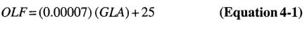
where:
OLF = The occupant load factor (square feet per person).
GLA = The gross leasable area (square feet).
81Exception: Tenant spaces attached to a covered mall building but with a means of egress system that is totally independent of the covered mall building shall not be considered as gross leasable area for determining the required means of egress for the covered mall building.
402.4.1.2 OLF range. The occupant load factor (OLF) is not required to be less than 30 and shall not exceed 50.
402.4.1.3 Anchor buildings. The occupant load of anchor buildings opening into the mall shall not be included in computing the total number of occupants for the mall.
402.4.1.4 Food courts. The occupant load of a food court shall be determined in accordance with Section 1004. For the purposes of determining the means of egress requirements for the mall, the food court occupant load shall be added to the occupant load of the covered mall building as calculated above.
402.4.2 Number of means of egress. Wherever the distance of travel to the mall from any location within a tenant space used by persons other than employees exceeds 75 feet ( 22 860 mm) or the tenant space has an occupant load of 50 or more, not less than two means of egress shall be provided.
402.4.3 Arrangements of means of egress. Assembly occupancies with an occupant load of 500 or more shall be so located in the covered mall building that their entrance will be immediately adjacent to a principal entrance to the mall and shall have not less than one-half of their required means of egress opening directly to the exterior of the covered mall building.
402.4.3.1 Anchor building means of egress. Required means of egress for anchor buildings shall be provided independently from the mall means of egress system. The occupant load of anchor buildings opening into the mall shall not be included in determining means of egress requirements for the mall. The path of egress travel of malls shall not exit through anchor buildings. Malls terminating at an anchor building where no other means of egress has been provided shall be considered as a dead-end mall.
402.4.4 Distance to exits. Within each individual tenant space in a covered mall building, the maximum distance of travel from any point to an exit or entrance to the mall shall not exceed 200 feet (60 960 mm).
The maximum distance of travel from any point within a mall to an exit shall not exceed 200 feet (60 960 mm).
402.4.5 Access to exits. Where more than one exit is required, they shall be so arranged that it is possible to travel in either direction from any point in a mall to separate exits. The minimum width of an exit passageway or corridor from a mall shall be 66 inches (1676 mm).
Exception: Dead ends not exceeding a length equal to twice the width of the mall measured at the narrowest location within the dead-end portion of the mall.
402.4.5.1 Exit passageways. Where exit passageways provide a secondary means of egress from a tenant space, doorways to the exit passageway shall be protected by 1-hour fire door assemblies that are self- or automatic-closing by smoke detection in accordance with Section 715.4.8.3.
402.4.6 Service areas fronting on exit passageways. Mechanical rooms, electrical rooms, building service areas and service elevators are permitted to open directly into exit passageways, provided the exit passageway is separated from such rooms with not less than 1-hour fire barriers constructed in accordance with Section 707 or horizontal assemblies constructed in accordance with Section 712, or both. The minimum fire protection rating of openings in the fire barriers shall be 1 hour.
402.5 Mall width. For the purpose of providing required egress, malls are permitted to be considered as corridors but need not comply with the requirements of Section 1005.1 of this code where the width of the mall is as specified in this section.
402.5.1 Minimum width. The minimum width of the mall shall be 20 feet (6096 mm). The mall width shall be sufficient to accommodate the occupant load served. There shall be a minimum of 10 feet (3048 mm) clear exit width to a height of 8 feet (2438 mm) between any projection of a tenant space bordering the mall and the nearest kiosk, vending machine, bench, display opening, food court or other obstruction to means of egress travel.
402.5.2 Minimum width open mall. The minimum floor and roof opening width above grade shall be 20 feet (9096 mm) in open malls.
402.6 Types of construction. The area of any covered mall building, including anchor buildings, of Types I, II, III and IV construction, shall not be limited provided the covered mall building and attached anchor buildings and parking garages are surrounded on all sides by a permanent open space of not less than 60 feet (18 288 mm) and the anchor buildings do not exceed three stories above grade plane. The allowable height and area of anchor buildings greater than three stories above grade plane shall comply with Section 503, as modified by Sections 504 and 506. The construction type of open parking garages and enclosed parking garages shall comply with Sections 406.3 and 406.4, respectively.
402.6.1 Reduced open space. The permanent open space of 60 feet (18 288 mm) shall be permitted to be reduced to not less than 40 feet (12 192 mm), provided the following requirements are met:
402.7 Fire-resistance-rated separation. Fire-resistance-rated separation is not required between tenant spaces and the mall. Fire-resistance-rated separation is not required between a food court and adjacent tenant spaces or the mall.
402.7.1 Attached garage. An attached garage for the storage of passenger vehicles having a capacity of not more than nine
82persons and open parking garages shall be considered as a separate building where it is separated from the covered mall building by not less than 2-hour fire barriers constructed in accordance with Section 707 or horizontal assemblies constructed in accordance with Section 712, or both.
Exception: Where an open parking garage or enclosed parking garage is separated from the covered mall building or anchor building a distance greater than 10 feet (3048 mm), the provisions of Table 602 shall apply. Pedestrian walkways and tunnels that attach the open parking garage or enclosed parking garage to the covered mall building or anchor building shall be constructed in accordance with Section 3104.
402.7.2 Tenant separations. Each tenant space shall be separated from other tenant spaces by a fire partition complying with Section 709. A tenant separation wall is not required between any tenant space and the mall.
402.7.3 Anchor building separation. An anchor building shall be separated from the covered mall building by fire walls complying with Section 706.
Exception: Anchor buildings of not more than three stories above grade plane that have an occupancy classification the same as that permitted for tenants of the covered mall building shall be separated by 2-hour fire-resistive fire barriers complying with Section 707.
402.7.3.1 Openings between anchor building and mall. Except for the separation between Group R-1 sleeping units and the mall, openings between anchor buildings of Type IA, IB, IIA and IIB construction and the mall need not be protected.
402.8 Interior finish. Interior wall and ceiling finishes within the mall and exits shall have a minimum flame spread index and smoke-developed index of Class B in accordance with Chapter 8. Interior floor finishes shall meet the requirements of Section 804.
[F] 402.9 Automatic sprinkler system. The covered mall building and buildings connected shall be equipped throughout with an automatic sprinkler system in accordance with Section 903.3.1.1, which shall comply with the following:
Exception: An automatic sprinkler system shall not be required in spaces or areas of open parking garages constructed in accordance with Section 406.3.
[F] 402.9.1 Standpipe system. The covered mall building shall be equipped throughout with a standpipe system as required by Section 905.3.3.
402.10 Smoke control. Where a covered mall building contains an atrium, a smoke control system shall be provided in accordance with Section 404.5.
Exception: A smoke control system is not required in covered mall buildings when an atrium connects only two stories.
402.11 Kiosks. Kiosks and similar structures (temporary or permanent) shall meet the following requirements:
402.12 Children‒s playground structures. Structures intended as children‘s playgrounds that exceed 10 feet (3048 mm) in height and 150 square feet (14 m2) in area shall comply with Sections 402.12.1 through 402.12.4.
402.12.1 Materials. Children‘s playground structures shall be constructed of noncombustible materials or of combustible materials that comply with the following:
402.12.2 Fire protection. Children's playground structures located within the small shall be provided with the same level of approved fire suppression and detection devices required for kiosks and similar structures.
402.12.3 Separation. Children's playground structures shall have a minimum horizontal separation from other structures within the mall of 20 feet (6090 mm).
402.12.4 Area limits. Children's playground structures shall not exceed 300 square feet (28 m2) in area, unless a special investigation has demonstrated adequate fire safety.
402.13 Security grilles and doors. Horizontal sliding or vertical security grilles or doors that are a part of a required means of egress shall conform to the following:
[F] 402.14 Standby power. Covered mall buildings exceeding 50,000 square feet (4645 m2) shall be provided with standby power systems that are capable of operating the emergency voice/alarm communication system.
[F] 402.15 Emergency voice/alarm communication system. Covered mall buildings exceeding 50,000 square feet (4645 m2) in total floor area shall be provided with an emergency voice/alarm communication system. Emergency voice/alarm communication systems serving a mall, required or otherwise, shall be accessible to the fire department. The system shall be provided in accordance with Section 907.5.2.2.
402.16 Plastic signs. Plastic signs affixed to the storefront of any tenant space facing the mall shall be limited as specified in Sections 402.16.1 through 402.16.5.2.
402.16.1 Area. Plastic signs shall not exceed 20 percent of the wall area facing the mall.
402.16.2 Height and width. Plastic signs shall not exceed a height of 36 inches (914 mm), except that if the sign is vertical, the height shall not exceed 96 inches (2438 mm) and the width shall not exceed 36 inches (914 mm).
402.16.3 Location. Plastic signs shall be located a minimum distance of 18 inches (457 mm) from adjacent tenants.
402.16.4 Plastics other than foam plastics. Plastics other than foam plastics used in signs shall be light-transmitting plastics complying with Section 2606.4 or shall have a self-ignition temperature of 650°F (343°C) or greater when tested in accordance with ASTM D 1929, and a flame spread index not greater than 75 and smoke-developed index not greater than 450 when tested in the manner intended for use in accordance with ASTM E 84 or UL 723 or meet the acceptance criteria of Section 803.1.2.1 when tested in accordance with NFPA 286.
402.16.4.1 Encasement. Edges and backs of plastic signs in the mall shall be fully encased in metal.
402.16.5 Foam plastics. Foam plastics used in signs shall have flame-retardant characteristics such that the sign has a maximum heat-release rate of 150 kilowatts when tested in accordance with UL 1975 and the foam plastics shall have the physical characteristics specified in this section. Foam plastics used in signs installed in accordance with Section 402.16 shall not be required to comply with the flame spread and smoke-developed indexes specified in Section 2603.3.
402.16.5.1 Density. The minimum density of foam plastics used in signs shall not be less than 20 pounds per cubic foot (pcf) (320 kg/m3).
402.16.5.2 Thickness. The thickness of foam plastic signs shall not be greater than ½ inch (12.7 mm).
[F] 402.17 Fire department access to equipment. Rooms or areas containing controls for air-conditioning systems, automatic fire-extinguishing systems or other detection, suppression or control elements shall be identified for use by the fire department.
403.1 Applicability. New high-rise buildings and new Group 1-2 occupancies having occupied floors located more than 75
84feet above the lowest level of fire department vehicle access shall comply with Sections 403.2 through 403.6.
Exception: The provisions of Sections 403.2 through 403.6 shall not apply to the following buildings and structures:
- Airport traffic control towers in accordance with Section 412.3.
- Open parking garages in accordance with Section 406.3.
- Buildings with a Group A-5 occupancy in accordance with Section 303.1.
- Special industrial occupancies in accordance with Section 503.1.1.
- Buildings such as power plants, lookout towers, steeples, grain houses and similar structures with non continuous human occupancy, when so determined by the enforcing agency.
For existing high-rise buildings, see Section 3414 and for existing Group R occupancies, see Section 3413.13.
For the purpose of this section, in determining the level from which the highest occupied floor is to be measured, the enforcing agency should exercise reasonable judgment, including consideration of overall accessibility to the building by fire department personnel and vehicular equipment. When a building is located on sloping terrain and there is building access on more than one level, the enforcing agency may select the level that provides the most logical and adequate fire department access.
403.1.1 Definitions. The following words and terms shall, for the purposes of this section and as used elsewhere in this code, have the meanings shown herein.
HIGH-RISE BUILDING. In other than Group 1-2 occupancies “high-rise buildings” as used in this code:
HIGH-RISE BUILDING ACCESS. An exterior door opening conforming to all of the following:
NEW HIGH-RISE BUILDING. A high-rise structure, the construction of which is commenced on or after July 1, 1974. For the purpose of this section, construction shall be deemed to have commenced when plans and specifications are more than 50 percent complete and have been presented to the local jurisdiction prior to July 1, 1974. Unless all provisions of this section have been met, the construction of such buildings shall commence on or before January 1, 1976.
403.2 Construction. The construction of high-rise buildings shall comply with the provisions of Sections 403.2.1 through 403.2.4.
403.2.1 Reduction in fire-resistance rating. The fire- resistance-rating reductions listed in Sections 403.2.1.1 and 403.2.1.2 shall be allowed in buildings that have sprinkler control valves equipped with supervisory initiating devices and water-flow initiating devices for each floor.
Exception: Buildings, or portions of buildings, classified as a Group H-1, H-2 or H-3 occupancy.
403.2.1.1 Type of construction. The following reductions in the minimum fire-resistance rating of the building elements in Table 601 shall be permitted as follows:
Exception: The required fire-resistance rating of the Structural Frame shall not be permitted to be reduced.
Exception: The required fire-resistance rating of the structural frame shall not be permitted to be reduced.
403.2.1.2 Shaft enclosures. For buildings not greater than 420 feet (128 m) in building height, the required fire-resistance rating of the fire barriers enclosing vertical shafts, other than exit enclosures and elevator hoistway enclosures, is permitted to be reduced to 1 hour where automatic sprinklers are installed within the shafts at the top and at alternate floor levels.
403.2.2 Seismic considerations. For seismic considerations, see Chapter 16.
85403.2.3 Structural integrity of exit enclosures and elevator hoistway enclosures. For high-rise buildings of occupancy category III or IV in accordance with Section 1604.5, and for all buildings that are more than 420 feet (128 m) in building height, exit enclosures and elevator hoistway enclosures shall comply with Sections 403.2.3.1 through 403.2.3.4.
403.2.3.1 Wall assembly. The wall assemblies making up the exit enclosures and elevator hoistway enclosures shall meet or exceed Soft Body Impact Classification Level 2 as measured by the test method described in ASTM C 1629/C 1629M.
403.2.3.2 Wall assembly materials. The face of the wall assemblies making up the exit enclosures and elevator hoistway enclosures that are not exposed to the interior of the exit enclosures or elevator hoistway enclosures shall be constructed in accordance with one of the following methods:
403.2.3.3 Concrete and masonry walls. Concrete or masonry walls shall be deemed to satisfy the requirements of Sections 403.2.3.1 and 403.2.3.2.
403.2.3.4 Other wall assemblies. Any other wall assembly that provides impact resistance equivalent to that required by Sections 403.2.3.1 and 403.2.3.2 for Hard Body Impact Classification Level 3, as measured by the test method described in ASTM C 1629/C 1629M, shall be permitted.
403.2.4 Sprayed fire-resistant materials (SFRM). The bond strength of the SFRM installed throughout the building shall be in accordance with Table 403.2.4.
| HEIGHT OF BUILDINGa | SFRM MINIMUM BOND STRENGTH |
|---|---|
| Up to 420 feet | 430 psf |
| Greater than 420 feet | 1,000 psf |
| For SI: 1 foot = 304.8 mm, 1 pound per square foot (psf) = 0.04|79 kW/m2. a. Above the lowest level of fire department vehicle access. | |
[F] 403.3 Automatic sprinkler system. Buildings and structures shall be equipped throughout with an automatic sprinkler system in accordance with Section 903.3.1.1 and a secondary water supply where required by Section 903.3.5.2. A sprinkler water-flow alarm-initiating device and a control valve with a supervisory signal-initiating device shall be provided at the lateral connection to the riser for each floor.
Exception: An automatic sprinkler system shall not be required in open parking garages in accordance with Section 406.3.
[F] 403.3.1 Number of sprinkler risers and system design. Each sprinkler system zone in buildings that are more than 420 feet (128 m) in building height shall be supplied by a minimum of two risers. Each riser shall supply sprinklers on alternate floors. If more than two risers are provided for a zone, sprinklers on adjacent floors shall not be supplied from the same riser.
[F] 403.3.1.1 Riser location. Sprinkler risers shall be placed in exit enclosures that are remotely located in accordance with Section 1015.2.
[F] 403.3.2 Water supply to required fire pumps. Required fire pumps shall be supplied by connections to a minimum of two water mains located in different streets. Separate supply piping shall be provided between each connection to the water main and the pumps. Each connection and the supply piping between the connection and the pumps shall be sized to supply the flow and pressure required for the pumps to operate.
Exception: Two connections to the same main shall be permitted provided the main is valved such that an interruption can be isolated so that the water supply will continue without interruption through at least one of the connections.
403.4 Emergency systems. The detection, alarm and emergency systems of high-rise buildings shall comply with Sections 403.4.1 through 403.4.8.
[F] 403.4.1 Smoke detection. Smoke detection shall be provided in accordance with Section 907.2.13.1.
[F] 403.4.2 Fire alarms systems. A fire alarm system shall be provided in accordance with Section 907.2.13.
[F] 403.4.3 Emergency voice/alarm communication system. An emergency voice/alarm communication system shall be provided in accordance with Section 907.5.2.2.
[F] 403.4.4 Emergency responder radio coverage. Emergency responder radio coverage shall be provided in accordance with Section 510 of the International Fire Code.
[F] 403.4.5 Fire command. A fire command center complying with Section 911 shall be provided in a location approved by the fire department.
403.4.6 Smoke control.
403.4.6.1 Smoke control system. High-rise buildings shall be provided with a passive or active smoke control system or combination thereof in accordance with Section 909.
[F] 403.4.7 Standby power. A standby power system complying with Chapter 27 shall be provided for standby power loads specified in Section 403.4.7.2.
86[F] 403.4.7.1 Special requirements for standby power systems. If the standby system is a generator set inside a building, the system shall be located in a separate room enclosed with 2-hour fire barriers constructed in accordance with Section 707 or horizontal assemblies constructed in accordance with Section 712, or both. System supervision with manual start and transfer features shall be provided at the fire command center.
[F] 403.4.7.2 Standby power loads. The following are classified as standby power loads:
[F] 403.4.8 Emergency power systems. An emergency power system complying with Chapter 27 shall be provided for emergency power loads specified in Section 403.4.8.1.
[F] 403.4.8.1 Emergency power loads. The following are classified as emergency power loads:
403.5 Means of egress and evacuation. The means of egress in high-rise buildings shall comply with Sections 403.5.1 through 403.5.6.
403.5.1 Remoteness of exit stairway enclosures. The required exit stairway enclosures shall be separated by a distance not less than 30 feet (9144 mm) or not less than one-fourth of the length of the maximum overall diagonal dimension of the building or area to be served, whichever is less. The distance shall be measured in a straight line between the nearest points of the exit stairway enclosures. In building with three or more exit stairway enclosures, at least two of the exit stairway enclosures shall comply with this section. Interlocking or scissor stairs shall be counted as one exit stairway.
403.5.2 Additional exit stairway. For buildings other than Group R-2 that are more than 420 feet (128 m) in building height, one additional exit stairway meeting the requirements of Sections 1009 and 1022 shall be provided in addition to the minimum number of exits required by Section 1021.1. The total width of any combination of remaining exit stairways with one exit stairway removed shall not be less than the total width required by Section 1005.1. Scissor stairs shall not be considered the additional exit stairway required by this section.
Exception: An additional exit stairway shall not be required to be installed in buildings having elevators used for occupant self-evacuation in accordance with Section 3008.
403.5.3 Stairway door operation. Stairway doors other than the exit discharge doors shall be permitted to be locked from the stairway side. Stairway doors that are locked from the stairway side shall be capable of being unlocked simultaneously without unlatching upon a signal from the fire command center. Upon failure of electrical power to the locking mechanism the door shall unlock.
403.5.3.1 Stairway communication system. A telephone or other two-way communications system connected to an approved constantly attended station shall be provided at not less than every fifth floor in each stairway where the doors to the stairway are locked.
403.5.4 Smokeproof exit enclosures. Every exit enclosure in high-rise buildings shall comply with Sections 909.20 and 1022.9. Every required level exit stairway in Group I-2 occupancies serving floors more than 75 feet (22 860 mm) above the lowest level of fire department vehicle access shall comply with Sections 909.20 and 1022.9.
403.5.5 Luminous egress path markings. Luminousegress path markings shall be provided in accordance with Section 1024.
403.5.6 Emergency escape and rescue. Emergency escape and rescue openings required by Section 1029 are not required.
403.6 Elevators. Elevator installation and operation in high-rise buildings shall comply with Chapter 30 and Sections 403.6.1 and 403.6.2.
Enclosed elevator lobbies shall be provided in accordance with Section 708.14.1. Exceptions 3, 5, 6 and 8 shall only be permitted where approved by the Fire Chief in accordance with Section 1.11.2.1.2 for all state-owned buildings, state-occupied buildings, and state institutions throughout the state.
403.6.1 Fire service access elevator. In buildings with an occupied floor more than 120 feet (36 576 mm) above the lowest level of fire department vehicle access, a minimum of one fire service access elevator shall be provided in accordance with Section 3007.
403.6.2 Occupant evacuation elevators. Where installed in accordance with Section 3008, passenger elevators for general public use shall be permitted to be used for occupant self-evacuation.
403.7 Existing high-rise buildings. For existing high-rise buildings, see Section 3414.
87404.1 General. In other than Group H occupancies, and where permitted by Exception 5 in Section 708.2, the provisions of this section shall apply to buildings or structures containing vertical openings defined herein as “Atriums.”
404.1.1 Definition. The following word and term shall, for the purposes of this chapter and as used elsewhere in this code, have the meaning shown herein.
ATRIUM. An opening connecting two or more stories other than enclosed stairways, elevators, hoistways, escalators, plumbing, electrical, air-conditioning or other equipment, which is closed at the top and not defined as a mall. Stories, as used in this definition, do not include balconies within assembly groups or mezzanines that comply with Section 505.
404.2 Use. The floor of the atrium shall not be used for other than low fire hazard uses and only approved materials and decorations in accordance with the International Fire Code shall be used in the atrium space.
Exception: The atrium floor area is permitted to be used for any approved use where the individual space is provided with an automatic sprinkler system in accordance with Section 903.3.1.1.
[F] 404.3 Automatic sprinkler protection. An approved automatic sprinkler system shall be installed throughout the entire building.
Exceptions:
- That area of a building adjacent to or above the atrium need not be sprinklered provided that portion of the building is separated from the atrium portion by not less than 2-hour fire barriers constructed in accordance with Section 707 or horizontal assemblies constructed in accordance with Section 712, or both.
- Where the ceiling of the atrium is more than 55 feet (16 764 mm) above the floor, sprinkler protection at the ceiling of the atrium is not required.
[F] 404.4 Fire alarm system. A fire alarm system shall be provided in accordance with Section 907.2.14.
404.5 Smoke control. A smoke control system shall be installed in accordance with Section 909.
Exception: Smoke control is not required for atriums that connect only two stories.
404.6 Enclosure of atriums. Atrium spaces shall be separated from adjacent spaces by a 1-hour fire barrier constructed in accordance with Section 707 or a horizontal assembly constructed in accordance with Section 712, or both.
Exceptions:
- A glass wall forming a smoke partition where automatic sprinklers are spaced 6 feet (1829 mm) or less along both sides of the separation wall, or on the room side only if there is not a walkway on the atrium side, and between 4 inches and 12 inches (102 mm and 305 mm) away from the glass and designed so that the entire surface of the glass is wet upon activation of the sprinkler system without obstruction. The glass shall be installed in a gasketed frame so that the framing system deflects without breaking (loading) the glass before the sprinkler system operates.
- A glass-block wall assembly in accordance with Section 2110 and having a ¾-hour fire protection rating.
- In other than Group I and R-2.1 occupancies, t he adjacent spaces of any three floors of the atrium shall not be required to be separated from the atrium where such spaces are accounted for in the design of the smoke control system.
[F] 404.7 Standby power. Equipment required to provide smoke control shall be connected to a standby power system in accordance with Section 909.11.
404.8 Interior finish. The interior finish of walls and ceilings of the atrium shall not be less than Class B with no reduction in class for sprinkler protection.
404.9 Travel distance. In other than the lowest level of the atrium, where the required means of egress is through the atrium space, the portion of exit access travel distance within the atrium space shall not exceed 200 feet (60 960 mm). The travel distance requirements for areas of buildings open to the atrium and where access to the exits is not through the atrium, shall comply with the requirements of Section 1016.
404.10 Group I and R-2.1 occupancy means of egress. Required means of egress from sleeping rooms in Group I and R-2.1 occupancies shall not pass through the atrium.
405.1 General. The provisions of this section apply to building spaces having a floor level used for human occupancy more than 30 feet (9144 mm) below the finished floor of the lowest level of exit discharge.
88Exceptions:
- One- and two-family dwellings, sprinklered in accordance with Section 903.3.1.3.
- Parking garages with automatic sprinkler systems in compliance with Section 405.3.
- Fixed guideway transit systems.
- Grandstands, bleachers, stadiums, arenas and similar facilities.
- Where the lowest story is the only story that would qualify the building as an underground building and has an area not exceeding 1,500 square feet (139 m2) and has an occupant load less than 10.
- Pumping stations and other similar mechanical spaces intended only for limited periodic use by service or maintenance personnel.
- [SFM] Winery Caves having a floor level used for human occupancy 30 feet (9144 mm) or less below the lowest level of exit discharge.
405.2 Construction requirements. The underground portion of the building shall be of Type I construction.
[F] 405.3 Automatic sprinkler system. The highest level of exit discharge serving the underground portions of the building and all levels below shall be equipped with an automatic sprinkler system installed in accordance with Section 903.3.1.1. Water-flow switches and control valves shall be supervised in accordance with Section 903.4.
405.4 Compartmentation. Compartmentation shall be in accordance with Sections 405.4.1 through 405.4.3.
405.4.1 Number of compartments. A building having a floor level more than 60 feet (18 288 mm) below the finished floor of the lowest level of exit discharge shall be divided into a minimum of two compartments of approximately equal size. Such compartmentation shall extend through the highest level of exit discharge serving the underground portions of the building and all levels below.
Exception: The lowest story need not be compartmented where the area does not exceed 1,500 square feet (139 m2) and has an occupant load of less than 10.
405.4.2 Smoke barrier penetration. The compartments shall be separated from each other by a smoke barrier in accordance with Section 710. Penetrations between the two compartments shall be limited to plumbing and electrical piping and conduit that are firestopped in accordance with Section 713. Doorways shall be protected by fire door assemblies that are automatic-closing by smoke detection in accordance with Section 715.4.8.3 and are installed in accordance with NFPA 105 and Section 715.4.3. Where provided, each compartment shall have an air supply and an exhaust system independent of the other compartments.
405.4.3 Elevators. Where elevators are provided, each compartment shall have direct access to an elevator. Where an elevator serves more than one compartment, an elevator lobby shall be provided and shall be separated from each compartment by a smoke barrier in accordance with Section 710. Doors shall be gasketed, have a drop sill and be automatic-closing by smoke detection in accordance with Section 715.4.8.3.
[F] 405.5 Smoke control system. A smoke control system shall be provided in accordance with Sections 405.5.1 and 405.5.2.
[F] 405.5.1 Control system. A smoke control system is required to control the migration of products of combustion in accordance with Section 909 and the provisions of this section. Smoke control shall restrict movement of smoke to the general area of fire origin and maintain means of egress in a usable condition.
[F] 405.5.2 Compartment smoke control system. Where compartmentation is required, each compartment shall have an independent smoke control system. The system shall be automatically activated and capable of manual operation in accordance with Sections 907.2.18 and 907.2.19.
[F] 405.6 Fire alarm systems. A fire alarm system shall be provided where required by Sections 907.2.18 and 907.2.19.
405.7 Means of egress. Means of egress shall be in accordance with Sections 405.7.1 and 405.7.2.
405.7.1 Number of exits. Each floor level shall be provided with a minimum of two exits. Where compartmentation is required by Section 405.4, each compartment shall have a minimum of one exit and shall also have an exit access doorway into the adjoining compartment.
405.7.2 Smokeproof enclosure. Every required stairway serving floor levels more than 30 feet (9144 mm) below the finished floor of its level of exit discharge shall comply with the requirements for a smokeproof enclosure as provided in Section 1022.9.
[F] 405.8 Standby power. A standby power system complying with Chapter 27 shall be provided standby power loads specified in Section 405.8.1.
[F] 405.8.1 Standby power loads. The following loads are classified as standby power loads:
Standby power shall be provided for elevators in accordance with Section 3003.
[F] 405.8.2 Pick-up time. The standby power system shall pick up its connected loads within 60 seconds of failure of the normal power supply.
[F] 405.9 Emergency power. An emergency power system complying with Chapter 27 shall be provided for emergency power loads specified in Section 405.9.1.
[F] 405.9.1 Emergency power loads. The following loads are classified as emergency power loads:
[F] 405.10 Standpipe system. The underground building shall be equipped throughout with a standpipe system in accordance with Section 905.
406.1 Private garages and carports.
406.1.1 Classification. Buildings or parts of buildings classified as Group U occupancies because of the use or character of the occupancy shall not exceed 1,000 square feet (93 m2) in area or one story in height except as provided in Section 406.1.2. Any building or portion thereof that exceeds the limitations specified in this section shall be classified in the occupancy group other than Group U that it most nearly resembles.
89406.1.2 Area increase. Group U occupancies used for the storage of private or pleasure-type motor vehicles where no repair work is completed or fuel is dispensed are permitted to be 3,000 square feet (279 m2) when the following provisions are met:
More than one 3,000-square-foot (279 m2) Group U occupancy shall be permitted to be in the same building, provided each 3,000-square-foot (279 m2) area is separated by fire walls complying with Section 706.
406.1.3 Garages and carports. Carports shall be open on at least two sides. Carport floor surfaces shall be of approved noncombustible material. Carports not open on at least two sides shall be considered a garage and shall comply with the provisions of this section for garages.
Exception: Asphalt surfaces shall be permitted at ground level in carports.
The area of floor used for parking of automobiles or other vehicles shall be sloped to facilitate the movement of liquids to a drain or toward the main vehicle entry doorway.
406.1.4 Separation. Separations shall comply with the following:
406.1.5 Automatic garage door openers. Automatic garage door openers, if provided, shall be listed in accordance with UL 325. See Health and Safety Code Sections 19890 and 19891 for additional provisions for residential garage door openers.
406.2 Parking garages.
406.2.1 Classification. Parking garages shall be classified as either open, as defined in Section 406.3, or enclosed and shall meet the appropriate criteria in Section 406.4. Also see Section 509 for special provisions for parking garages.
406.2.2 Clear height. The clear height of each floor level in vehicle and pedestrian traffic areas shall not be less than 7 feet (2134 mm). [HCD 1-AC, DSA-AC] The clear height of vehicle and pedestrian areas required to be accessible shall comply with Chapter 11A or Chapter 11B, as applicable.
406.2.3 Guards. Guards shall be provided in accordance with Section 1013. Guards serving as vehicle barrier systems shall comply with Sections 406.2.4 and 1013.
406.2.4 Vehicle barrier systems. Vehicle barrier systems not less than 2 feet 9 inches (835 mm) high shall be placed at the end of drive lanes, and at the end of parking spaces where the vertical distance to the ground or surface directly below is greater than 1 foot (305 mm). Vehicle barrier systems shall comply with the loading requirements of Section 1607.7.3.
Exception: Vehicle storage compartments in a mechanical access parking garage.
406.2.5 Ramps. Vehicle ramps shall not be considered as required exits unless pedestrian facilities are provided. Vehicle ramps that are utilized for vertical circulation as well as for parking shall not exceed a slope of 1:15 (6.67 percent).
406.2.6 Floor surface. Parking surfaces shall be of concrete or similar noncombustible and nonabsorbent materials.
The area of floor used for parking of automobiles or other vehicles shall be sloped to facilitate the movement of liquids to a drain or toward the main vehicle entry doorway.
Exceptions:
- Asphalt parking surfaces shall be permitted at ground level.
- Floors of Group S-2 parking garages shall not be required to have a sloped surface.
406.2.7 Mixed occupancy separation. Parking garages shall be separated from other occupancies in accordance with Section 508.1.
406.2.8 Special hazards. Connection of a parking garage with any room in which there is a fuel-fired appliance shall be by means of a vestibule providing a two-doorway separation.
Exception: A single door shall be allowed provided the sources of ignition in the appliance are at least 18 inches (457 mm) above the floor.
406.2.9 Attached to rooms. Openings from a parking garage directly into a room used for sleeping purposes shall not be permitted.
406.3 Open parking garages.
406.3.1 Scope. Except where specific provisions are made in Sections 406.3.2 through 406.3.13, other requirements of this code shall apply.
406.3.2 Definitions. The following words and terms shall, for the purposes of this chapter and as used elsewhere in this code, have the meanings shown herein.
MECHANICAL-ACCESS OPEN PARKING GARAGES. Open parking garages employing parking machines, lifts, elevators or other mechanical devices for vehicles moving from and to street level and in which public occupancy is prohibited above the street level.
OPEN PARKING GARAGE. A structure or portion of a structure with the openings as described in Section 406.3.3.1 on two or more sides that is used for the parking or storage of private motor vehicles as described in Section 406.3.4.
RAMP-ACCESS OPEN PARKING GARAGES. Open parking garages employing a series of continuously rising floors or a series of interconnecting ramps between floors permitting the movement of vehicles under their own power from and to the street level.
406.3.3 Construction. Open parking garages shall be of Type I, II or IV construction. Open parking garages shall meet the design requirements of Chapter 16. For vehicle barrier systems, see Section 406.2.4.
406.3.3.1 Openings. For natural ventilation purposes, the exterior side of the structure shall have uniformly distributed openings on two or more sides. The area of such openings in exterior walls on a tier must be at least 20 percent of the total perimeter wall area of each tier. The aggregate length of the openings considered to be providing natural ventilation shall considered a minimum of 40 percent of the perimeter of the tier. Interior walls shall be at least 20 percent open with uniformly distributed openings.
Exception: Openings are not required to be distributed over 40 percent of the building perimeter where the required openings are uniformly distributed over two opposing sides of the building.
406.3.4 Uses. Mixed uses shall be allowed in the same building as an open parking garage subject to the provisions of Sections 402.7.1., 406.3.13, 508.1, 509.3, 509.4 and 509.7.
406.3.5 Area and height. Area and height of open parking garages shall be limited as set forth in Chapter 5 for Group S-2 occupancies and as further provided for in Section 508.1.
406.3.5.1 Single use. When the open parking garage is used exclusively for the parking or storage of private motor vehicles, with no other uses in the building, the area and height shall be permitted to comply with Table 406.3.5, along with increases allowed by Section 406.3.6.
Exception: The grade-level tier is permitted to contain an office, waiting and toilet rooms having a total combined area of not more than 1,000 square feet (93 m2). Such area need not be separated from the open parking garage.
In open parking garages having a spiral or sloping floor, the horizontal projection of the structure at any cross section shall not exceed the allowable area per parking tier. In the case of an open parking garage having a continuous spiral floor, each 9 feet 6 inches (2896 mm) of height, or portion thereof, shall be considered a tier.
The clear height of a parking tier shall not be less than 7 feet (2134 mm), except that a lower clear height is permitted in mechanical-access open parking garages where approved by the building official.
406.3.6 Area and height increases. The allowable area and height of open parking garages shall be increased in accordance with the provisions of this section. Garages with sides open on three-fourths of the building’s perimeter are permitted to be increased by 25 percent in area and one tier in height. Garages with sides open around the entire building’s perimeter are permitted to be increased by 50 percent in area and one tier in height. For a side to be considered open under the above provisions, the total area of openings along the side shall not be less than 50 percent of the interior area of the side at each tier and such openings shall be equally distributed along the length of the tier.
| TYPE OF CONSTRUCTION | AREA PER TIER (square feet) | |||
|---|---|---|---|---|
| HEIGHT (in tiers) | ||||
| Ramp access | Mechanical access | |||
| Automatic sprinkler system | ||||
| No | Yes | |||
| IA | Unlimited | Unlimited | Unlimited | Unlimited |
| IB | Unlimited | 12 tiers | 12 tiers | 18 tiers |
| IIA | 50,000 | 10 tiers | 10 tiers | 15 tiers |
| IIB | 50,000 | 8 tiers | 8 tiers | 12 tiers |
| IV | 50,000 | 4 tiers | 4 tiers | 4 tiers |
| For SI: 1 square foot = 0.0929 m2. | ||||
Allowable tier area in Table 406.3.5 shall be increased for open parking garages constructed to heights less than the table maximum. The gross tier area of the garage shall not exceed that permitted for the higher structure. At least three sides of each such larger tier shall have continuous horizontal openings not less than 30 inches (762 mm) in clear height extending for at least 80 percent of the length of the sides and no part of such larger tier shall be more than 200 feet (60 960 mm) horizontally from such an opening. In addition, each such opening shall face a street or yard accessible to a street with a width of at least 30 feet (9144 mm) for the full length of the opening, and standpipes shall be provided in each such tier.
Open parking garages of Type II construction, with all sides open, shall be unlimited in allowable area where the building height does not exceed 75 feet (22 860 mm). For a side to be considered open, the total area of openings along the side shall not be less than 50 percent of the interior area of the side at each tier and such openings shall be equally distributed along the length of the tier. All portions of tiers shall be within 200 feet (60 960 mm) horizontally from such openings or other natural ventilation openings as defined in Section 406.3.3.1. These openings shall be permitted to be provided in courts with a minimum dimension of 20 feet (6096 mm) for the full width of the openings.
406.3.7 Fire separation distance. Exterior walls and openings in exterior walls shall comply with Tables 601 and 602. The distance to an adjacent lot line shall be determined in accordance with Table 602 and Section 705.
406.3.8 Means of egress. Where persons other than parking attendants are permitted, open parking garages shall meet the means of egress requirements of Chapter 10. Where no persons other than parking attendants are permitted, there shall not be less than two 36-inch-wide (914 mm)exit stairways. Lifts shall be permitted to be installed for use of employees only, provided they are completely enclosed by noncombustible materials.
406.3.9 Standpipes. Standpipes shall be installed where required by the provisions of Chapter 9.
406.3.10 Sprinkler systems. Where required by other provisions of this code, automatic sprinkler systems and standpipes shall be installed in accordance with the provisions of Chapter 9.
406.3.11 Enclosure of vertical openings. Enclosure shall not be required for vertical openings except as specified in Section 406.3.8.
406.3.12 Ventilation. Ventilation, other than the percentage of openings specified in Section 406.3.3.1, shall not be required.
406.3.13 Prohibitions. The following uses and alterations are not permitted:
406.4 Enclosed parking garages.
406.4.1 Heights and areas. Enclosed vehicle parking garages and portions thereof that do not meet the definition of open parking garages shall be limited to the allowable heights and areas specified in Table 503 as modified by Sections 504, 506 and 507. Roof parking is permitted.
406.4.2 Ventilation. A mechanical ventilation system shall be provided in accordance with the California Mechanical Code.
406.5 Motor fuel-dispensing facilities.
406.5.1 Construction. Motor fuel-dispensing facilities shall be constructed in accordance with the California Fire Code and Sections 406.5.1 through 406.5.3.
406.5.2 Vehicle fueling pad. The vehicle shall be fueled on noncoated concrete or other approved paving material having a resistance not exceeding 1 megohm as determined by the methodology in EN 1081.
406.5.3 Canopies. Canopies under which fuels are dispensed shall have a clear, unobstructed height of not less than 13 feet 6 inches (4115 mm) to the lowest projecting element in the vehicle drive-through area. Canopies and their supports over pumps shall be of noncombustible materials,fire-retardant-treated wood complying with Chapter 23, wood of Type IV sizes or of construction providing 1-hour fire resistance. Combustible materials used in or on a canopy shall comply with one of the following:
406.5.3.1 Canopies used to support gaseous hydrogen systems. Canopies that are used to shelter dispensing operations where flammable compressed gases are located on the roof of the canopy shall be in accordance with the following:
406.6 Repair garages.
406.6.1 General. Repair garages shall be constructed in accordance with the California Fire Code and Sections 406.6.1 through 406.6.6. This occupancy shall not include motor fuel-dispensing facilities, as regulated in Section 406.5.
406.6.2 Mixed uses. Mixed uses shall be allowed in the same building as a repair garage subject to the provisions of Section 508.1.
406.6.3 Ventilation. Repair garages shall be mechanically ventilated in accordance with the California Mechanical Code. The ventilation system shall be controlled at the entrance to the garage.
406.6.4 Floor surface. Repair garage floors shall be of concrete or similar noncombustible and nonabsorbent materials.
Exception: Slip-resistant, nonabsorbent, interior floor finishes having a critical radiant flux not more than 0.45 W⁄cm2, as determined by NFPA 253, shall be permitted.
406.6.5 Heating equipment. Heating equipment shall be installed in accordance with the California Mechanical Code.
[F] 406.6.6 Gas detection system. Repair garages used for repair of vehicles fueled by nonodorized gases, such as hydrogen and nonodorized LNG, shall be provided with an approved flammable gas detection system.
[F]406.6.6.1 System design. The flammable gas detection system shall be calibrated to the types of fuels or gases used by vehicles to be repaired. The gas detection system shall be designed to activate when the level of flammable gas exceeds 25 percent of the lower explosive limit. Gas detection shall also be provided in lubrication or chassis repair pits of garages used for repairing nonodorized LNG-fueled vehicles.
[F] 406.6.6.2 Operation. Activation of the gas detection system shall result in all of the following:
[F] 406.6.6.3 Failure of the gas detection system. Failure of the gas detection system shall result in the deactivation of the heating system, activation of the mechanical ventilation system when the system is interlocked with the gas detection system and cause a trouble signal to sound in an approved location.
406.7 Electric Vehicle. [SFM]
406.7.1 Electric Vehicle. An automotive-type vehicle for highway use, such as passenger automobiles, buses, trucks, vans and the like, primarily powered by an electric motor that draws current from a rechargeable storage battery, fuel cell, photovoltaic array or other source of electric current. For the purpose of this chapter, electric motorcycles and similar type vehicles and off-road self-propelled electric vehicles such as industrial trucks, hoists, lifts, transports, golf carts, airline ground support equipment, tractors, boats and the like, are not included.
406.7.2 Charging. In any building or interior area used for charging electric vehicles, electrical equipment shall be installed in accordance with the California Electrical Code.
406.7.3 Ventilation. Mechanical exhaust ventilation, when required by the California Electrical Code shall be provided at a rate as required by Article 625 or as required by Section 1203 of the California Building Code whichever is greater. The ventilation system shall include both the supply and exhaust equipment and shall be permanently installed and located to intake supply air from the outdoors, and vent the exhaust directly to, the outdoors without conducting the exhaust air through other spaces within the building.
Exception: Positive pressure ventilation systems shall only be allowed in buildings or areas that have been designed and approved for that application.
406.7.4 Electrical Interface. The electrical supply circuit to electrically powered mechanical ventilation equipment shall be interlocked with the recharging equipment used to supply the vehicle(s) being charged, and shall remain energized during the entire charging cycle. Electric vehicle recharging equipment shall be marked or labeled in accordance with the California Electrical Code.
Exceptions:
- Exhaust ventilation shall not be required in areas with an approved engineered ventilation system, which maintains a hydrogen gas concentration at less than 25 percent of the lower flammability limit.
- Mechanical exhaust ventilation for hydrogen shall not be required where the charging equipment utilized is installed and listed for indoor charging of electric vehicles without ventilation.
407.1 General. Occupancies in Group I-2 and I-2.1 shall comply with the provisions of Sections 407.1 through 407.9 and other applicable provisions of this code.
407.2 Corridors.Corridors in occupancies in Group I-2 and I-2.1 shall be continuous to the exits and separated from other areas in accordance with Section 407.3 except spaces conforming to Sections 407.2.1 through 407.2.4.
407.2.1 Waiting and similar areas. Waiting areas and similar spaces constructed as required for corridors shall be
93permitted to be open to a corridor, only where all of the following criteria are met:
407.2.2 Nurses’ stations. Spaces for doctors’ and nurses’ charting, communications and related clerical areas shall be permitted to be open to the corridor, when such spaces are constructed as required for corridors. [SFM] Nurses’ stations in new and existing facilities, see the California Code of Regulations, Title 19, Division 1, Chapter 1, Subchapter 1, Article 3, Section 3.11(d) for storage and equipment requirements.
407.2.3 Mental health treatment areas. Areas wherein mental health patients who are not capable of self-preservation are housed, or group meeting or multipurpose therapeutic spaces other than incidental accessory occupancies in accordance with Section 508.2.5, under continuous supervision by facility staff, shall be permitted to be open to the corridor, where the following criteria are met:
407.2.4 Gift shops. Gift shops less than 500 square feet (46.5 m2) in area shall be permitted to be open to the corridor provided the gift shop and storage areas are fully sprinklered and storage areas are protected in accordance with Section 508.2.5.
407.3 Corridor walls.Corridor walls shall be constructed as fire partitions in accordance with Section 709.
407.3.1 Corridor doors.Corridor doors in fully sprinklered buildings, other than those in a wall required to be rated by Section 508.2.5 or for the enclosure of a vertical opening or an exit, shall not have a required fire protection rating, but shall provide an effective barrier to limit the transfer of smoke and shall be equipped with positive latching. Roller latches are not permitted. Other doors shall conform to Section 715.4. In Group I-2 Occupancies, self-closing or automatic-closing devices are not required on corridor doors to patient sleeping rooms, treatment rooms, and offices located in areas specified in Sections 1224 and 1225, excluding offices specified in Sections 1224.21 and 1225.8.
407.3.1.1 Swing of corridor doors. Corridor doors, other than those equipped with self-closing or automatic-closing devices shall not swing into the required width of corridors.
407.3.2 Locking devices. Locking devices that restrict access to the patient room from the corridor, and that are operable only by staff from the corridor side, shall not restrict the means of egress from the patient room except for patient rooms in mental health facilities.
407.3.3 Glazing. In fully sprinklered buildings, fixed fully tempered or laminated glass in wood or metal frames may be used in corridor walls, provided the glazed area does not exceed 25 percent of the areas of the corridor wall of the room. The total area of glass in corridor walls is not limited when the glazing is fixed ¼-inch-thick (6.4 mm) wired glass in steel frames and the size of individual glazed panel does not exceed 1,296 square inches (0.836 m2).
407.4 Smoke barriers.Smoke barriers shall be provided to subdivide every story used by patients for sleeping or treatment and to divide other stories with an occupant load of 50 or more persons, into at least two smoke compartments. Such stories shall be divided into smoke compartments with an area of not more than 22,500 square feet (2092 m2) and the travel distance from any point in a smoke compartment to a smoke barrier door shall not exceed 200 feet (60 960 mm). The smoke barrier shall be in accordance with Sections 710 and 909.5.
Exceptions:
- This requirement shall not apply to Group I-2.1 less than 10,000 ft2 (929 m2).
- An area in an adjoining occupancy shall be permitted to serve as a smoke compartment for a Group I-2.1 facility if the following criteria are met:
- The separating wall and both compartments meet the requirements of 407.4.
- The Group I-2.1 is less than 22,500 ft2(2100 m2).
- Access from the Group I-2.1 to the other occupancy is unrestricted.
407.4.1 Refuge area. At least 30 net square feet (2.8 m 2) per patient shall be provided within the aggregate area of corridors, patient rooms, treatment rooms, lounge or dining areas and other low-hazard areas on each side of each smoke barrier. On floors not housing patients confined to a bed or litter, at least 6 net square feet (0.56 m2) per occupant shall
94be provided on each side of each smoke barrier for the total number of occupants in adjoining smoke compartments.
407.4.2 Independent egress. At least two means of egress shall be provided from each smoke compartment created by smoke barriers. Means of egress may pass through adjacent compartments provided it does not return through the smoke compartment from which means of egress originated.
407.4.3 Horizontal assemblies. Horizontal assemblies supporting smoke barriers required by this section shall be designed to resist the movement of smoke and shall comply with Section 712.9.
[F] 407.5 Automatic sprinkler system. Every facility as specified herein wherein more than six clients or patients are housed or cared for on the premises on a 24-hour-per-day-basis shall have installed and maintained in an operable condition in every building or portion thereof where clients or patients are housed, an automatic sprinkler system of a type approved by the state fire marshal. The provisions of this subsection shall apply to every person, firm or corporation establishing, maintaining or operating a hospital, children’s home, children’s nursery or institution, or a home or institution for the care of aged or persons with dementia or other cognitive impairments, or any institution for persons with mental illness or persons with developmental disabilities and any nursing or convalescent home, and to any state-owned or state-occupied building used for any of the types of facilities specified herein.
Exceptions:
- This section shall not apply to homes or institutions for the 24-hour-per-day care of ambulatory children if all of the following conditions are satisfied:
- The buildings or portions thereof in which children are housed are not more than two stories in height and are constructed and maintained in accordance with regulations adopted by the state fire marshal.
- The buildings or portions thereof housing more than six such children shall have installed and maintained in an operable condition therein, a fire alarm system of a type approved by the state fire marshal. Such system shall be activated by detectors responding to invisible particles of combustion other than heat, except that detectors used in closets, usable under-floor areas, storage rooms, bathrooms, attached garages, attics, plenums, laundry rooms and rooms of similar use, may be heat-responsive devices.
- The building or portions thereof do not house persons with mental illness or children with developmental disabilities.
- This section shall not apply to any one-story building or structure of an institution or home for the care of the aged providing 24-hour-per-day care if such building or structure is used or intended to be used for the housing of no more than six ambulatory aged persons. Such buildings or institutions shall have installed and maintained in an operable condition herein a fire alarm system of a type approved by the state fire marshal. Such system shall be activated by detectors responding to either visible or invisible particles of combustion other than heat, except that detectors used in closets, usable under-floor areas, storage rooms, bathrooms, attached garages, attics, plenums, laundry rooms and rooms of similar use, may be heat-responsive devices.
- This section shall not apply to occupancies or any alterations thereto conforming to the construction provisions of this exception which were under construction or in existence on March 4, 1972. “Under construction” as used in this exception shall mean that actual work had been performed on the construction site and shall not be construed to mean that the hospital, home, nursery, institution, sanitarium or any portion thereof, was or is in the planning stage. The provisions of this exception shall apply to those buildings or structures having bearing walls and structural flame protected in accordance with the provisions of Column Type 1A of Table 601.
- In detention facilities where inmates are not restrained.
The provisions of this section shall not apply to any facility used to house six or less persons on the premises.
407.5.1 When a new addition is to be made to an unsprinklered building or structure as permitted by this subsection, such new addition shall be sprinklered as required by this section and shall be separated from the existing building or structures by not less than a two-hour fire-resistive fire barrier.
When a sprinkler system is added to an existing unsprinklered building or structure, the sprinklered area(s) shall be separated from the remainder of the building by not less than a one-hour fire-resistive fire barrier.
The provisions of this section do not apply to any facility used to house six or less persons on the premises.
[F] 407.6 Fire alarm system. A fire alarm system shall be provided in accordance with Section 907.2.6.
[F] 407.7 Automatic fire detection. See Section 907.2.6.2.
407.8 Secured yards. Grounds are permitted to be fenced and gates therein are permitted to be equipped with locks, provided that safe dispersal areas having 30 net square feet (2.8 m2) for bed and litter patients and 6 net square feet (0.56 m2) for ambulatory patients and other occupants are located between the building and the fence. Such provided safe dispersal areas shall not be located less than 50 feet (15 240 mm) from the building they serve. Each safe dispersal area shall have a minimum of two exits. The aggregate clear width of exits from a safe dispersal area shall be determined on the basis of not less than one exit unit of 22 inches (559 mm) for each 500 persons to be accommodated, and no exit shall be less than 44 inches (1118 mm) in width. Gates shall not be installed across corridors or passageways leading to such dispersal areas unless they comply with egress requirements. Keys to gate locks shall be provided in accordance with the California Fire Code.
95407.9 Hyperbaric facilities. Hyperbaric facilities in Group I-2 occupancies shall meet the requirements contained in Chapter 20 of NFPA 99.
407.10 Special Hazards.
407.10.1 Storage and handling of flammable, combustible liquids and hazardous materials shall be in accordance with the California Fire Code.
407.10.2 All exterior openings in a boiler room or room containing central heating equipment, if located below openings in another story, or if less than 10 feet (3048 mm) from other doors or windows of the same building, shall be protected by a fire assembly having a three-fourths-hour fire protection rating.
407.10.3 Safety padding. See Sections 308.1 and 408.14.
407.10.4 Floor Surfaces. Rooms occupied by patients whose personal liberties are restrained shall have noncombustible floor surfaces see Sections 308.1 and 804.4.2.
408.1 General. Occupancies in Group I-3 shall comply with the provisions of Sections 408.1 through 408.10 and other applicable provisions of this code (See Section 308.4).
408.1.1 Definition. The following words and terms shall, for the purposes of this chapter and as used elsewhere in this code, have the meanings shown herein.
CELL. A housing unit in a detention or correctional facility for the confinement of not more than two inmates or prisoners.
CELL COMPLEX. A cluster or group of cells or dormitories in a jail, prison or other detention facility, together with rooms used for accessory purposes, all of which open into the cell complex, and are used for functions such as dining, counseling, exercise, classrooms, sick call, visiting, storage, staff offices, control rooms or similar functions, and interconnecting corridors all within the cell complex.
CELL TIERS. Cells, dormitories and accessory spaces. Cell tiers are located one level above the other, and do not exceed two levels per floor. A cell tier shall not be considered a story or mezzanine.
CENTRAL CONTROL BUILDING. A secure building within a prison where the fire and life safety systems, communication systems, security systems and exterior lighting systems are monitored and where security operations necessitate the remote locking of required means of egress or at the door with a key to maintain a high security area.
DAY ROOM. A room which is adjacent to a cell, or cell tier, or dormitory and which is used as a dining, exercise or other activity room for inmates.
DORMITORY. An area occupied by no less than three inmates.
HOLDING FACILITY. A detention or correctional facility or area where inmates, staff and public are not housed but are restrained.
HOUSING UNIT. An area intended to lodge inmates on a 24-hour basis where accommodations are provided for sleeping.
RESTRAINT. The physical retention of a person within a room, cell or holding facility by any means, or within a building by means of locked doors.
SALLYPORT. A security vestibule with two or more doors or gates where the intended purpose is to prevent continuous and unobstructed passage by allowing the release of only one door or gate at a time.
SMALL MANAGEMENT YARD. An exterior exercise yard within a Group I-3 prison used for inmate exercise for a maximum of 2 hours per day, constructed in accordance with Section 408.1.2.3.
408.1.2 Construction. Group I-3 Occupancies shall be housed in buildings of Type IA or Type IB.
Exception: Such occupancies may be housed in one-story buildings of Type IIA, Type IIIA or Type VA construction provided the floor area does not exceed 5,200 square feet (483 m2) between fire walls of two-hour fire-resistive construction with openings protected by fire assemblies having 1- and 1½-hour fire-protection rating.
408.1.2.1 Nonbearing walls and partitions interior. Nonbearing cell or dormitory walls within cell complexes shall be of noncombustible construction.
408.1.2.2 Cells with open bars. In buildings protected throughout by an automatic sprinkler system and automatic fire detection system, corridor doors or walls of cells and dormitories, may be of open bars, perforated metal, grilles, or other similar construction.
408.2 Other occupancies. Buildings or portions of buildings in Group I-3 occupancies where security operations necessitate the locking of required means of egress shall be permitted to be classified as a different occupancy. Occupancies classified as other than Group I-3 shall meet the applicable requirements of this code for that occupancy provided provisions are made for the release of occupants at all times.
Means of egress from detention and correctional occupancies that traverse other use areas shall, as a minimum, conform to requirements for detention and correctional occupancies.
Exceptions:
408.3 Means of egress. Except as modified or as provided for in this section, the provisions of Chapter 10 shall apply.
408.3.1. Door width. Doors to resident sleeping units shall have a clear width of not less than 28 inches (711 mm).
408.3.1.1 Cell doors shall open outwardly or slide laterally.
408.3.2 Sliding doors. Where doors in a means of egress are of the horizontal-sliding type, the force to slide the door to its fully open position shall not exceed 50 pounds (220 N) with a perpendicular force against the door of 50 pounds (220 N).
408.3.3 Guard tower doors. A hatch or trap door not less than 16 square feet (610 m2) in area through the floor and having minimum dimensions of not less than 2 feet (610 mm) in any direction shall be permitted to be used as a portion of the means of egress from guard towers.
408.3.4 Spiral stairways. Spiral stairways that conform to the requirements of Section 1009.9 are permitted for access to and between staff locations.
408.3.5 Ship ladders. Ship ladders shall be permitted for egress from control rooms or elevated facility observation rooms in accordance with Section 1009.11.
408.3.6 Exit discharge.
408.3.6.1 Exits are permitted to discharge into a fenced or walled courtyard. Enclosed yards or courts shall be of a size to accommodate all occupants, a minimum of 50 feet (15 240 mm) from the building with a net area of 3 square feet (1.4 m2) per person. A gate shall be provided from the safe dispersal area to allow for the necessary relocation of occupants.
408.3.6.2 Exterior fenced enclosures and fenced enclosures utilized for recreational or activity purposes, used for exit termination for more than 20 persons, and which do not provide a safe dispersal area, shall have not less than two exits.
408.3.6.3 Fenced enclosure utilized for recreational or activity purposes only, for more than 49 people, and which do not provide a safe dispersal area, shall be provided with not less than two exits.
408.3.6.4 Fenced enclosure located on roofs of buildings one or more stories in height shall be provided with not less than two exits regardless of occupant load.
408.3.6.5 Fenced enclosures utilized for Central Control Buildings not normally occupied and not accessed by inmates or the general public are permitted to have only one exit from the fenced enclosure. These fenced enclosures shall only be occupied during emergency response conditions by not more than 29 prison staff occupants. Access to the fenced area shall be controlled remotely or at the gate with a key.
408.3.7 Sallyports. A sallyport shall be permitted in a means of egress where there are provisions for continuous and unobstructed passage through the sallyport during an emergency egress condition.
408.3.8 Exit enclosures.
408.3.8.1. One of the required exit enclosures in each building shall be permitted to have glazing installed in doors and interior walls at each landing level providing access to the enclosure, provided that the following conditions are met:
408.3.8.2 Where the number and arrangement of exits complies with the requirements of Chapter 10, other stairways which occur within the secure area of the detention facility and are not used for required exiting but are used primarily for the movement of inmates and security staff need not extend to the exterior.
408.3.9 Dead-end balconies. Exit balconies serving cell tiers shall not extend more than 50 feet (15 240 mm) beyond an exit stairway.
408.4 Locks. Egress doors are permitted to be locked in accordance with the applicable use condition. Doors from a refuge area to the exterior are permitted to be locked with a key in lieu of locking methods described in Section 408.4.1. The keys to unlock the exterior doors shall be available at all times and the locks shall be operable from both sides of the door. Security hardware may be used on any fire-rated door.
408.4.1 Remote release. Remote release of locks on doors in a means of egress shall be provided with reliable means of operation, remote from the resident living areas, to release locks on all required doors. In Occupancy Conditions 3 or 4, the arrangement, accessibility and security of the release mechanism(s) required for egress shall be such that with the minimum available staff at any time, the lock mechanisms are capable of being released within 2 minutes.
Exception: Provisions for remote locking and unlocking of occupied rooms in Occupancy Condition 4 are not required provided that not more than 10 locks are necessary
97to be unlocked in order to move occupants from one smoke compartment to a refuge area within 3 minutes. The opening of necessary locks shall be accomplished with not more than two separate keys.
408.4.2 Power-operated doors and locks. Power-operated sliding doors or power-operated locks for swinging doors shall be operable by a manual release mechanism at the door, and either emergency power or a remote mechanical operating release shall be provided.
Exception: Emergency power is not required in facilities with 10 locks or less complying with the exception to Section 408.4.1.
408.4.3 Redundant operation. Mechanically operated sliding doors or mechanically operated locks shall be provided with a mechanically operated release mechanism at each door and shall be provided with a remote release control.
408.4.4 Relock capability. Doors remotely unlocked under emergency conditions shall not automatically relock when closed unless specific action is taken at the remote location to enable doors to relock.
408.5 Protection of vertical openings. Any vertical opening shall be protected by a shaft enclosure in accordance with Section 708, or shall be in accordance with Section 408.5.1.
408.5.1 Floor openings. The open space in front of a cell tier and connected chases, not exceeding two tiers in height, shall not be considered a vertical shaft and need not meet the fire-resistive shaft enclosure requirements of Section 708.
408.5.2 Shaft openings in communicating floor levels. Where a floor opening is permitted between communicating floor levels of a housing unit in accordance with Section 408.5.1, plumbing chases serving vertically staked individual cells contained with the housing unit shall be permitted without a shaft enclosure.
408.6 Smoke barrier. Occupancies in Group I-3 shall have smoke barriers complying with Sections 408.8 and 710 to divide every story occupied by residents for sleeping, or any other story having an occupant load of 50 or more persons, into at least two smoke compartments.
Exception: Spaces having a direct exit to one of the following, provided that the locking arrangement of the doors involved complies with the requirements for doors at the smoke barrier for the use condition involved:
408.6.1 Smoke compartments. The maximum number of residents in any smoke compartment shall be 200. The travel distance to a door in a smoke barrier from any room door required as exit access shall not exceed 150 feet (45 720 mm). The travel distance to a door in a smoke barrier from any point in a room shall not exceed 200 feet (60 960 mm).
408.6.2 Refuge area. At least 6 net square feet (0.56 m2) per occupant shall be provided on each side of each smoke barrier for the total number of occupants in adjoining smoke compartments. This space shall be readily available wherever the occupants are moved across the smoke barrier in a fire emergency.
408.6.3 Independent egress. A means of egress shall be provided from each smoke compartment created by smoke barriers without having to return through the smoke compartment from which means of egress originates.
408.7 Security glazing. In occupancies in Group I-3, windows and doors in 1 -hour fire barriers constructed in accordance with Section 707, fire partitions constructed in accordance with Section 709 and smoke barriers constructed in accordance with Section 710 shall be permitted to have security glazing installed provided that the following conditions are met.
408.8 Subdivision areas. Each cell complex shall be separated from other cell complexes or other spaces by a smoke-tight partition.
408.8.1 Smoke-tight doors. Doors in openings in partitions required to be smoke tight by Section 408.8 shall be substantial doors, of construction that will resist the passage of smoke. Latches and door closures are not required on cell doors.
408.9 Windowless buildings. For the purposes of this section, a windowless building or portion of a building is one with nonopenable windows, windows not readily breakable or without windows. Windowless buildings shall be provided with an engineered smoke control system to provide a tenable environment for exiting from the smoke compartment in the area of fire origin in accordance with Section 909 for each windowless smoke compartment.
[F] 408.10 Fire alarm system. A fire alarm system shall be provided in accordance with Section 907.2.6.3.
408.11 Emergency and standby power systems. Special electrical systems, exit illumination, power installations and alternate on-site electrical supplies shall be provided for every building or portion of a building housing 10 or more inmates in a detention
98or correctional facility in accordance with the provisions of the California Electrical Code. There shall be a source of emergency power in all detention facilities capable of providing minimal lighting in all housing units, activity areas, corridors, stairs and central control points, and to maintain fire and life safety, security, communications and alarm systems.
408.12 Windows. In security areas within cell complexes sprinklered throughout, the area of glazing in one-hour corridor walls and smoke barrier walls shall not be restricted, provided:
Windows required to have a three-fourths-hour fire-resistive rating or windows protected by fixed security glazing, as delineated in Items 1 and 2 above, may have an area not greater than 84 square feet (7.8 m2) with neither width nor height exceeding 12 feet (3658 mm).
408.13 Safety padding. Padding material used on walls, floors and ceilings in Group 1 and R-2.1 occupancies shall be of an approved type tested in accordance with the procedures established by State Fire Marshal Standard 12-8-100, Room Fire Test for Wall and Ceiling Materials, California Code of Regulations, Title 24, Part 12.
408.14 Small management yards.
408.14.1 General. The provisions of Sections 408.14.1 through 408.14.4 shall apply to small management yards. Small management yards may be used by a maximum of two occupants at any one time for a maximum of 2 hours per day.
408.14.2 Construction. Small management yards shall be constructed in accordance with all of the following:
Exception: Low voltage devices dedicated for the operation of toilets.
408.14.3 Fire protection system provisions.
408.14.3.1 Automatic sprinkler systems. An automatic sprinkler system shall be provided in accordance with Section 903.1.1
Exception: Small management yards where a distance of 10 feet (3048 mm) is maintained from all buildings or structures and 4 feet (1220 mm) is maintained from containment fencing.
408.14.3.2 Fire alarm systems. An approved fire alarm system shall be provided in accordance with Section 907.
Exception: Small management yards where a distance of 10 feet (3048 mm) is maintained from all buildings or structures and 4 feet (1220 mm) is maintained from containment fencing.
408.14.4 Means of egress. Except as modified or as provided for in this section, the provisions of Section 408.3 and Chapter 10 shall apply. Small management yards shall comply with all of the following:
408.14.5 Special provisions. Inmate exercise clothing and toilet paper tissue shall be the only combustibles materials permitted in small management yards.
409.1 General. The provisions of Sections 409.1 through 409.5 shall apply to rooms in which ribbon-type cellulose acetate or other safety film is utilized in conjunction with electricarc, xenon or other light-source projection equipment that develops hazardous gases, dust or radiation. Where cellulose nitrate film is utilized or stored, such rooms shall comply with NFPA 40.
409.1.1 Projection room required. Every motion picture machine projecting film as mentioned within the scope of this section shall be enclosed in a projection room. Appurtenant electrical equipment, such as rheostats, transformers and generators, shall be within the projection room or in an adjacent room of equivalent construction.
409.2 Construction of projection rooms. Every projection room shall be of permanent construction consistent with the construction requirements for the type of building in which the projection room is located. Openings are not required to be protected.
99The room shall have a floor area of not less than 80 square feet (7.44 m2) for a single machine and at least 40 square feet (3.7 m2) for each additional machine. Each motion picture projector, floodlight, spotlight or similar piece of equipment shall have a clear working space of not less than 30 inches by 30 inches (762 mm by 762 mm) on each side and at the rear thereof, but only one such space shall be required between two adjacent projectors. The projection room and the rooms appurtenant thereto shall have a ceiling height of not less than 7 feet 6 inches (2286 mm). The aggregate of openings for projection equipment shall not exceed 25 percent of the area of the wall between the projection room and the auditorium. Openings shall be provided with glass or other approved material, so as to close completely the opening.
409.3 Projection room and equipment ventilation. Ventilation shall be provided in accordance with the California Mechanical Code.
409.3.1 Supply air. Each projection room shall be provided with adequate air supply inlets so arranged as to provide well-distributed air throughout the room. Air inlet ducts shall provide an amount of air equivalent to the amount of air being exhausted by projection equipment. Air is permitted to be taken from the outside; from adjacent spaces within the building, provided the volume and infiltration rate is sufficient; or from the building air-conditioning system, provided it is so arranged as to provide sufficient air when other systems are not in operation.
409.3.2 Exhaust air. Projection rooms are permitted to be exhausted through the lamp exhaust system. The lamp exhaust system shall be positively interconnected with the lamp so that the lamp will not operate unless there is the required airflow. Exhaust air ducts shall terminate at the exterior of the building in such a location that the exhaust air cannot be readily recirculated into any air supply system. The projection room ventilation system is permitted to also serve appurtenant rooms, such as the generator and rewind rooms.
409.3.3 Projection machines. Each projection machine shall be provided with an exhaust duct that will draw air from each lamp and exhaust it directly to the outside of the building. The lamp exhaust is permitted to serve to exhaust air from the projection room to provide room air circulation. Such ducts shall be of rigid materials, except for a flexible connector approved for the purpose. The projection lamp or projection room exhaust system, or both, is permitted to be combined but shall not be interconnected with any other exhaust or return system, or both, within the building.
409.4 Lighting control. Provisions shall be made for control of the auditorium lighting and the means of egress lighting systems of theaters from inside the projection room and from at least one other convenient point in the building.
409.5 Miscellaneous equipment. Each projection room shall be provided with rewind and film storage facilities.
410.1 Applicability. The provisions of Sections 410.1 through 410.7 shall apply to all parts of buildings and structures that contain stages or platforms and similar appurtenances as herein defined.
410.2 Definitions. The following words and terms shall, for the purposes of this section and as used elsewhere in this code, have the meanings shown herein.
FLY GALLERY. A raised floor area above a stage from which the movement of scenery and operation of other stage effects are controlled.
GRIDIRON. The structural framing over a stage supporting equipment for hanging or flying scenery and other stage effects.
PINRAIL. A rail on or above a stage through which belaying pins are inserted and to which lines are fastened.
PLATFORM. A raised area within a building used for worship, the presentation of music, plays or other entertainment; the head table for special guests; the raised area for lecturers and speakers; boxing and wrestling rings; theater-in-the-round stages; and similar purposes wherein there are no overhead hanging curtains, drops, scenery or stage effects other than lighting and sound. A temporary platform is one installed for not more than 30 days.
PROSCENIUM WALL. The wall that separates the stage from the auditorium or assembly seating area.
STAGE. A space within a building utilized for entertainment or presentations, which includes overhead hanging curtains, drops, scenery or stage effects other than lighting and sound.
410.3 Stages. Stage construction shall comply with Sections 410.3.1 through 410.3.7.
410.3.1 Stage construction. Stages shall be constructed of materials as required for floors for the type of construction of the building in which such stages are located.
Exceptions:
- Stages of Type IIB or IV construction with a nominal 2-inch (51 mm) wood deck, provided that the stage is separated from the other areas in accordance with Section 410.3.4.
- In buildings of Types IIA, IIIA and VA construction, a fire-resistance-rated floor is not required, provided the space below the stage is equipped with an automatic fire-extinguishing system in accordance with Section 903 or 904.
- In all types of construction, the finished floor shall be constructed of wood or approved noncombustible materials. Openings through stage floors shall be equipped with tight-fitting, solid wood trap doors with approved safety locks.
410.3.1.1 Stage height and area. Stage areas shall be measured to include the entire performance area and adjacent backstage and support areas not separated from the performance area by fire-resistance-rated construc-
100tion. Stage height shall be measured from the lowest point on the stage floor to the highest point of the roof or floor deck above the stage.
410.3.2 Galleries, gridirons, catwalks and pinrails. Beams designed only for the attachment of portable or fixed theater equipment, gridirons, galleries and catwalks shall be constructed of approved materials consistent with the requirements for the type of construction of the building; and a fire-resistance rating shall not be required. These areas shall not be considered to be floors, stories, mezzanines or levels in applying this code.
Exception: Floors of fly galleries and catwalks shall be constructed of any approved material.
410.3.3 Exterior stage doors. Where protection of openings is required, exterior exit doors shall be protected with fire door assemblies that comply with Section 715. Exterior openings that are located on the stage for means of egress or loading and unloading purposes, and that are likely to be open during occupancy of the theater, shall be constructed with vestibules to prevent air drafts into the auditorium.
410.3.4 Proscenium wall. Where the stage height is greater than 50 feet (15 240 mm), all portions of the stage shall be completely separated from the seating area by a proscenium wall with not less than a 2-hour fire-resistance rating extending continuously from the foundation to the roof.
410.3.5 Proscenium curtain. Where a proscenium wall is required to have a fire-resistance rating, the stage opening shall be provided with a fire curtain complying with NFPA 80 or an approved water curtain complying with Section 903.3.1.1 or, in facilities not utilizing the provisions of smoke-protected assembly seating in accordance with Section 1028.6.2, a smoke control system complying with Section 909 or natural ventilation designed to maintain the smoke level at least 6 feet (1829 mm) above the floor of the means of egress.
410.3.6 Scenery. Combustible materials used in sets and scenery shall meet the fire propagation performance criteria of NFPA 701, in accordance with Section 806 and the California Fire Code. Foam plastics and materials containing foam plastics shall comply with Section 2603 and the California Fire Code.
410.3.7 Stage ventilation. Emergency ventilation shall be provided for stages larger than 1,000 square feet (93 m2) in floor area, or with a stage height greater than 50 feet (15 240 mm). Such ventilation shall comply with Section 410.3.7.1 or 410.3.7.2.
410.3.7.1 Roof vents. Two or more vents constructed to open automatically by approved heat-activated devices and with an aggregate clear opening area of not less than 5 percent of the area of the stage shall be located near the center and above the highest part of the stage area. Supplemental means shall be provided for manual operation of the ventilator. Curbs shall be provided as required for skylights in Section 2610.2. Vents shall be labeled.
[F] 410.3.7.2 Smoke control. Smoke control in accordance with Section 909 shall be provided to maintain the smoke layer interface not less than 6 feet (1829 mm) above the highest level of the assembly seating or above the top of the proscenium opening where a proscenium wall is provided in compliance with Section 410.3.4.
410.4 Platform construction. Permanent platforms shall be constructed of materials as required for the type of construction of the building in which the permanent platform is located. Permanent platforms are permitted to be constructed of fire-retardant-treated wood for Types I, II and IV construction where the platforms are not more than 30 inches (762 mm) above the main floor, and not more than one-third of the room floor area and not more than 3,000 square feet (279 m2) in area. Where the space beneath the permanent platform is used for storage or any purpose other than equipment, wiring or plumbing, the floor assembly shall not be less than 1-hour fire-resistance-rated construction. Where the space beneath the permanent platform is used only for equipment, wiring or plumbing, the underside of the permanent platform need not be protected.
410.4.1 Temporary platforms. Platforms installed for a period of not more than 30 days are permitted to be constructed of any materials permitted by the code. The space between the floor and the platform above shall only be used for plumbing and electrical wiring to platform equipment.
410.5 Dressing and appurtenant rooms. Dressing and appurtenant rooms shall comply with Sections 410.5.1 through 410.5.3.
410.5.1 Separation from stage. The stage shall be separated from dressing rooms, scene docks, property rooms, workshops, storerooms and compartments appurtenant to the stage and other parts of the building by fire barriers constructed in accordance with Section 707 or horizontal assemblies constructed in accordance with Section 712, or both. The minimum fire-resistance rating shall be 2 hours for stage heights greater than 50 feet (15 240 mm) and 1 hour for stage heights of 50 feet (15 240 mm) or less.
410.5.2 Separation from each other. Dressing rooms, scene docks, property rooms, workshops, storerooms and compartments appurtenant to the stage shall be separated from each other by not less than 1-hour fire barriers constructed in accordance with Section 707 or horizontal assemblies constructed in accordance with Section 712, or both.
410.5.3 Stage exits. At least one approved means of egress shall be provided from each side of the stage and from each side of the space under the stage. At least one means of escape shall be provided from each fly gallery and from the gridiron. A steel ladder, alternating tread device or spiral stairway is permitted to be provided from the gridiron to a scuttle in the stage roof.
[F] 410.6 Automatic sprinkler system. Stages shall be equipped with an automatic fire-extinguishing system in accordance with Chapter 9. Sprinklers shall be installed under the roof and gridiron and under all catwalks and galleries over
101the stage. Sprinklers shall be installed in dressing rooms, performer lounges, shops and storerooms accessory to such stages.
Exceptions:
- Sprinklers are not required under stage areas less than 4 feet (1219 mm) in clear height that are utilized exclusively for storage of tables and chairs, provided the concealed space is separated from the adjacent spaces by not less than 5/8-inch (15.9 mm) Type X gypsum board.
- Sprinklers are not required for stages 1,000 square feet (93 m2) or less in area and 50 feet (15 240 mm) or less in height where curtains, scenery or other combustible hangings are not retractable vertically. Combustible hangings shall be limited to a single main curtain, borders, legs and a single backdrop.
- Sprinklers are not required within portable orchestra enclosures on stages.
[F] 410.7 Standpipes. Standpipe systems shall be provided in accordance with Section 905.
411.1 General. Special amusement buildings having an occupant load of 50 or more shall comply with the requirements for the appropriate Group A occupancy and Sections 411.1 through 411.8. Amusement buildings having an occupant load of less than 50 shall comply with the requirements for a Group B occupancy and Sections 411.1 through 411.8.
Exception: Amusement buildings or portions thereof that are without walls or a roof and constructed to prevent the accumulation of smoke.
For flammable decorative materials, see the California Fire Code.
411.2 Definition. The following word and term shall, for the purpose of this section and as used elsewhere in this code, have the meaning shown herein.
SPECIAL AMUSEMENT BUILDING. A special amusement building is any temporary or permanent building or portion thereof that is occupied for amusement, entertainment or educational purposes and that contains a device or system that conveys passengers or provides a walkway along, around or over a course in any direction so arranged that the means of egress path is not readily apparent due to visual or audio distractions or is intentionally confounded or is not readily available because of the nature of the attraction or mode of conveyance through the building or structure.
[F] 411.3 Automatic fire detection. Special amusement buildings shall be equipped with an automatic fire detection system in accordance with Section 907.
[F] 411.4 Automatic sprinkler system. Special amusement buildings shall be equipped throughout with an automatic sprinkler system in accordance with Section 903.3.1.1. Where the special amusement building is temporary, the sprinkler water supply shall be of an approved temporary means.
Exception: Automatic sprinklers are not required where the total floor area of a temporary special amusement building is less than 1,000 square feet (93 m2) and the travel distance from any point to an exit is less than 50 feet (15 240 mm).
[F] 411.5 Alarm. Actuation of a single smoke detector, the automatic sprinkler system or other automatic fire detection device shall immediately sound an alarm at the building at a constantly attended location from which emergency action can be initiated including the capability of manual initiation of requirements in Section 907.2.12.2.
[F] 411.6 Emergency voice/alarm communications system. An emergency voice/alarm communications system shall be provided in accordance with Sections 907.2.12 and 907.5.2.2, which is also permitted to serve as a public address system and shall be audible throughout the entire special amusement building.
411.7 Exit marking. Exit signs shall be installed at the required exit or exit access doorways of amusement buildings in accordance with this section and Section 1011. Approved directional exit markings shall also be provided. Where mirrors, mazes or other designs are utilized that disguise the path of egress travel such that they are not apparent, approved and listed low-level exit signs that comply with Section 1011.4, and directional path markings listed in accordance with UL 1994, shall be provided and located not more than 8 inches (203 mm) above the walking surface and on or near the path of egress travel. Such markings shall become visible in an emergency. The directional exit marking shall be activated by the automatic fire detection system and the automatic sprinkler system in accordance with Section 907.2.12.2.
411.7.1 Photo luminescent exit signs. Where photo luminescent exit signs are installed, activating light source and viewing distance shall be in accordance with the listing and markings of the signs.
411.8 Interior finish. The interior finish shall be Class A in accordance with Section 803.1.
412.1 General. Aircraft-related occupancies shall comply with Sections 412.1 through 412.7 and the California Fire Code.
412.2 Definitions. The following words and terms shall, for the purposes of this chapter and as used elsewhere in this code, have the meanings shown herein.
FIXED BASE OPERATOR (FBO). A commercial business granted the right by the airport sponsor to operate on an airport and provide aeronautical services, such as fueling, hangaring, tie-down and parking, aircraft rental, aircraft maintenance and flight instruction.
HELIPORT. An area of land or water or a structural surface that is used, or intended for the use, for the landing and taking off of helicopters, and any appurtenant areas that are used, or intended for use, for heliport buildings or other heliport facilities.
102HELISTOP. The same as “heliport, ” except that no fueling, defueling, maintenance, repairs or storage of helicopters is permitted.
RESIDENTIAL AIRCRAFT HANGAR. An accessory building less than 2,000 square feet (186 m2) and 20 feet (6096 mm) in building height constructed on a one- or two-family property where aircraft are stored. Such use will be considered as a residential accessory use incidental to the dwelling.
TRANSIENT AIRCRAFT. Aircraft based at another location and at the transient location for not more than 90 days.
412.3 Airport traffic control towers.
412.3.1 General. The provisions of Sections 412.3.1 through 412.3.6 shall apply to airport traffic control towers not exceeding 1,500 square feet (140 m2) per floor occupied only for the following uses:
412.3.2 Type of construction. Airport traffic control towers shall be constructed to comply with the height and area limitations of Table 412.3.2.
| TYPE OF CONSTRUCTION | HEIGHTa (feet) | MAXIMUM AREA (square feet) |
|---|---|---|
| IA | Unlimited | 1,500 |
| IB | 240 | 1,500 |
| IIA | 100 | 1,500 |
| IIB | 85 | 1,500 |
| IIIA | 65 | 1,500 |
| For SI: 1 foot = 304.8 mm, 1 square foot = 0.0929 m2. | ||
| a. Height to be measured from grade plane to cab floor. | ||
412.3.3 Egress. A minimum of one exit stairway shall be permitted for airport traffic control towers of any height provided that the occupant load per floor does not exceed 15. The stairway shall conform to the requirements of Section 1009. The stairway shall be separated from elevators by a minimum distance of one-half of the diagonal of the area served measured in a straight line. The exit stairway and elevator hoistway are permitted to be located in the same shaft enclosure, provided they are separated from each other by a 4-hour fire barrier having no openings. Such stairway shall be pressurized to a minimum of 0.15 inch of water column (43 Pa) and a maximum of 0.35 inch of water column (101 Pa) in the shaft relative to the building with stairway doors closed. Stairways need not extend to the roof as specified in Section 1009.11. The provisions of Section 403 do not apply.
Exception: Smokeproof enclosures as set forth in Section 1022.9 are not required where required stairways are pressurized.
[F] 412.3.4 Automatic fire detection systems. Airport traffic control towers shall be provided with an automatic fire detection system installed in accordance with Section 907.2.
[F] 412.3.5 Standby power. A standby power system that conforms to Chapter 27 shall be provided in airport traffic control towers more than 65 feet (19 812 mm) in height. Power shall be provided to the following equipment:
412.3.6 Accessibility. [DSA-AC] In air traffic control towers, an accessible route shall not be required to serve the cab and the equipment areas on the floor immediately below the cab.
412.4 Aircraft hangars. Aircraft hangars shall be in accordance with Sections 412.4.1 through 412.4.6.
412.4.1 Exterior walls. Exterior walls located less than 30 feet (9144 mm) from lot lines or a public way shall have a fire-resistance rating not less than 2 hours.
412.4.2 Basements. Where hangars have basements, floors over basements shall be of Type IA construction and shall be made tight against seepage of water, oil or vapors. There shall be no opening or communication between basements and the hangar. Access to basements shall be from outside only.
412.4.3 Floor surface. Floors shall be graded and drained to prevent water or fuel from remaining on the floor. Floor drains shall discharge through an oil separator to the sewer or to an outside vented sump.
Exception: Aircraft hangars with individual lease spaces not exceeding 2,000 square feet (186 m2) each in which servicing, repairing or washing is not conducted and fuel is not dispensed shall have floors that are graded toward the door, but shall not require a separator.
412.4.4 Heating equipment. Heating equipment shall be placed in another room separated by 2-hour fire barriers constructed in accordance with Section 707 or horizontal assemblies constructed in accordance with Section 712, or both. Entrance shall be from the outside or by means of a vestibule providing a two-doorway separation.
103Exceptions:
- Unit heaters and vented infrared radiant heating equipment suspended at least 10 feet (3048 mm) above the upper surface of wings or engine enclosures of the highest aircraft that are permitted to be housed in the hangar and at least 8 feet (2438 mm) above the floor in shops, offices and other sections of the hangar communicating with storage or service areas.
- A single interior door shall be allowed, provided the sources of ignition in the appliances are at least 18 inches (457 mm) above the floor.
412.4.5 Finishing. The process of “doping,” involving use of a volatile flammable solvent, or of painting, shall be carried on in a separate detached building equipped with automatic fire-extinguishing equipment in accordance with Section 903.
412.4.6 Fire suppression. Aircraft hangars shall be provided with a fire suppression system designed in accordance with NFPA 409, based upon the classification for the hangar given in Table 412.4.6.
Exception: When a fixed base operator has separate repair facilities on site, Group II hangars operated by a fixed base operator used for storage of transient aircraft only shall have a fire suppression system, but the system is exempt from foam requirements.
412.4.6.1 Hazardous operations. Any Group III aircraft hangar according to Table 412.4.6 that contains hazardous operations including, but not limited to, the following shall be provided with a Group I or II fire suppression system in accordance with NFPA 409 as applicable:
412.4.6.2 Separation of maximum single fire areas. Maximum single fire areas established in accordance with hangar classification and construction type in Table 412.4.6 shall be separated by 2-hour fire walls constructed in accordance with Section 706.
412.5 Residential aircraft hangars. Residential aircraft hangars as defined in Section 412.2 shall comply with Sections 412.5.1 through 412.5.2.
412.5.1 Fire separation. A hangar shall not be attached to a dwelling unless separated by a fire barrier having a fire-resistance rating of not less than 1 hour. Such separation shall be continuous from the foundation to the underside of the roof and unpierced except for doors leading to the dwelling unit. Doors into the dwelling unit must be equipped with self-closing devices and conform to the requirements of Section 715 with at least a 4-inch (102 mm) noncombustible raised sill. Openings from a hanger directly into a room used for sleeping purposes shall not be permitted.
412.5.2 Egress. A hangar shall provide two means of egress. One of the doors into the dwelling shall be considered as meeting only one of the two means of egress.
[F] 412.5.3 Smoke alarms. Smoke alarms shall be provided within the hangar in accordance with Section 907.2.21.
412.5.4 Independent systems. Electrical, mechanical and plumbing drain, waste and vent (DWV) systems installed within the hangar shall be independent of the systems installed within the dwelling. Building sewer lines shall be permitted to be connected outside the structures.
Exception: Smoke detector wiring and feed for electrical subpanels in the hangar.
| MAXIMUM SINGLE FIRE AREA, SQ. FT. | TYPE OF CONSTRUCTION | ||||||||
|---|---|---|---|---|---|---|---|---|---|
| IA | IB | IIA | IIB | IIIA | IIIB | IV | VA | VB | |
| ≥40,001 | Group I | Group I | Group I | Group I | Group I | Group I | Group I | Group I | Group I |
| 40,000 | Group II | Group II | Group II | Group II | Group II | Group II | Group II | Group II | Group II |
| 30,000 | Group III | Group II | Group II | Group II | Group II | Group II | Group II | Group II | Group II |
| 20,000 | Group III | Group III | Group II | Group II | Group II | Group II | Group II | Group II | Group II |
| 15,000 | Group III | Group III | Group III | Group II | Group III | Group II | Group III | Group II | Group II |
| 12,000 | Group III | Group III | Group III | Group III | Group III | Group III | Group III | Group II | Group II |
| 8,000 | Group III | Group III | Group III | Group III | Group III | Group III | Group III | Group III | Group II |
| 5,000 | Group III | Group III | Group III | Group III | Group III | Group III | Group III | Group III | Group III |
| For SI: 1 foot = 304.8 mm, 1 square foot = 0.0929 m2. | |||||||||
| a. Aircraft hangars with a door height greater than 28 feet shall be provided with fire suppression for a Group I hangar regardless of maximum fire area. | |||||||||
| b. Groups shall be as classified in accordance with NFPA 409. | |||||||||
| c. Membrane structures complying with Section 3102 shall be classified as a Group IV hangar. | |||||||||
412.5.5 Height and area limits. Residential aircraft hangars shall not exceed 2,000 square feet (186 m2) in area and 20 feet (6096 mm) in building height.
[F] 412.6 Aircraft paint hangars. Aircraft painting operations where flammable liquids are used in excess of the maximum allowable quantities per control area listed in Table 307.1(1) shall be conducted in an aircraft paint hangar that complies with the provisions of Sections 412.6.1 through 412.6.6.
[F] 412.6.1 Occupancy group. Aircraft paint hangars shall be classified as Group H-2. Aircraft paint hangars shall comply with the applicable requirements of this code and the California Fire Code for such occupancy.
[F] 412.6.2 Construction. The aircraft paint hangar shall be of Type I or II construction.
[F] 412.6.3 Operations. Only those flammable liquids necessary for painting operations shall be permitted in quantities less than the maximum allowable quantities per control area in Table 307.1(1). Spray equipment cleaning operations shall be conducted in a liquid use, dispensing and mixing room.
[F] 412.6.4 Storage. Storage of flammable liquids shall be in a liquid storage room.
[F] 412.6.5 Fire suppression. Aircraft paint hangars shall be provided with fire suppression as required by NFPA 409.
[F] 412.6.6 Ventilation. Aircraft paint hangars shall be provided with ventilation as required in the California Mechanical Code.
412.7 Heliports and helistops. Heliports and helistops shall be permitted to be erected on buildings or other locations where they are constructed in accordance with Sections 412.7.1 through 412.7.4.
412.7.1 Size. The landing area for helicopters less than 3,500 pounds (1588 kg) shall be a minimum of 20 feet (6096 mm) in length and width. The landing area shall be surrounded on all sides by a clear area having a minimum average width at roof level of 15 feet (4572 mm) but with no width less than 5 feet (1524 mm).
412.7.2 Design. Helicopter landing areas and the supports thereof on the roof of a building shall be noncombustible construction. Landing areas shall be designed to confine any flammable liquid spillage to the landing area itself and provisions shall be made to drain such spillage away from any exit or stairway serving the helicopter landing area or from a structure housing such exit or stairway. For structural design requirements, see Section 1605.4.
412.7.3 Means of egress. The means of egress from heliports and helistops shall comply with the provisions of Chapter 10. Landing areas located on buildings or structures shall have two or more means of egress. For landing areas less than 60 feet (18 288 mm) in length or less than 2,000 square feet (186 m2) in area, the second means of egress is permitted to be a fire escape, alternating tread device or ladder leading to the floor below.
412.7.4 Rooftop heliports and helistops. Rooftop heliports and helistops shall comply with NFPA 418.
413.1 General. High-piled stock or rack storage in any occupancy group shall comply with the California Fire Code.
413.2 Attic, under-floor and concealed spaces. Attic, under-floor and concealed spaces used for storage of combustible materials shall be protected on the storage side as required for 1-hour fire-resistance-rated construction. Openings shall be protected by assemblies that are self-closing and are of noncombustible construction or solid wood core not less than 1¾ inch (45 mm) in thickness.
Exceptions:
- Areas protected by approved automatic sprinkler systems.
- Group R-3 and U occupancies.
[F] 414.1 General. The provisions of Sections 414.1 through 414.7 shall apply to buildings and structures occupied for the manufacturing, processing, dispensing, use or storage of hazardous materials.
[F] 414.1.1 Other provisions. Buildings and structures with an occupancy in Group H shall also comply with the applicable provisions of Section 415 and the California Fire Code. For Group L occupancies see Section 443.
[F] 414.1.2 Materials. The safe design of hazardous material occupancies is material dependent. Individual material requirements are also found in Sections 307 and 415, and in the California Mechanical Code and the California Fire Code.
[F] 414.1.2.1 Aerosols. Level 2 and 3 aerosol products shall be stored and displayed in accordance with the California Fire Code. See Section 311.2 and the California Fire Code for occupancy group requirements.
[F] 414.1.3 Information required. A report shall be submitted to the building official identifying the maximum expected quantities of hazardous materials to be stored, used in a closed system and used in an open system, and subdivided to separately address hazardous material classification categories based on Tables 307.1(1) and 307.1(2). The methods of protection from such hazards, including but not limited to control areas, fire protection systems and Group H occupancies shall be indicated in the report and on the construction documents. The opinion and report shall be prepared by a qualified person, firm or corporation approved by the building official and provided without charge to the enforcing agency.
For buildings and structures with an occupancy in Group H, separate floor plans shall be submitted identifying the locations of anticipated contents and processes so as to reflect the nature of each occupied portion of every building and structure.
[F] 414.2 Control areas. Control areas shall comply with Sections 414.2.1 through 414.2.5 and the California Fire Code.
105414.2.1 Construction requirements. Control areas shall be separated from each other by fire barriers constructed in accordance with Section 707 or horizontal assemblies constructed in accordance with Section 712, or both.
[F] 414.2.2 Percentage of maximum allowable quantities. The percentage of maximum allowable quantities of hazardous materials per control area permitted at each floor level within a building shall be in accordance with Table 414.2.2.
[F] 414.2.3 Number. The maximum number of control areas within a building shall be in accordance with Table 414.2.2.
414.2.4 Fire-resistance-rating requirements. The required fire-resistance rating for fire barriers shall be in accordance with Table 414.2.2. The floor assembly of the control area and the construction supporting the floor of the control area shall have a minimum 2-hour fire-resistance rating.
Exception: The floor assembly of the control area and the construction supporting the floor of the control area are allowed to be 1-hour fire-resistance rated in buildings of Types IIA, IIIA and VA construction, provided that both of the following conditions exist:
- The building is equipped throughout with an automatic sprinkler system in accordance with Section 903.3.1.1; and
- The building is three stories or less above grade plane.
[F] 414.2.5 Hazardous material in Group M display and storage areas and in Group S storage areas. The aggregate quantity of nonflammable solid and nonflammable or noncombustible liquid hazardous materials permitted within a single control area of a Group M display and storage area, a Group S storage area or an outdoor control area is permitted to exceed the maximum allowable quantities per control area specified in Tables 307.1(1) and 307.1(2) without classifying the building or use as a Group H occupancy, provided that the materials are displayed and stored in accordance with the California Fire Code and quantitiesdo not exceed the maximum allowable specified in Table 414.2.5(1).
In Group M occupancy wholesale and retail sales uses, indoor storage of flammable and combustible liquids shall not exceed the maximum allowable quantities per control area as indicated in Table 414.2.5(2), provided that the materials are displayed and stored in accordance with the California Fire Code.
The maximum quantity of aerosol products in Group M occupancy retail display areas, storage areas adjacent to retail display areas and retail storage areas shall be in accordance with the California Fire Code.
[F] 414.3 Ventilation. Rooms, areas or spaces of Group H in which explosive, corrosive, combustible, flammable or highly toxic dusts, mists, fumes, vapors or gases are or may be emitted due to the processing, use, handling or storage of materials shall be mechanically ventialted as required by the California Fire Code and the California Mechanical Code.
Ducts conveying explosives or flammable vapors, fumes or dusts shall extend directly to the exterior of the building without entering other spaces. Exhaust ducts shall not extend into or through ducts and plenums.
Exception: Ducts conveying vapor or fumes having flammable constituents less than 25 percent of their lower flammable limit (LFL) are permitted to pass through other spaces.
Emissions generated at workstations shall be confined to the area in which they are generated as specified in the California Fire Code. and the California Mechanical Code.
The location of supply and exhaust openings shall be in accordance with the California Mechanical Code. Exhaust air contaminated by highly toxic material shall be treated in accordance with the California Fire Code.
A manual shutoff control for ventilation equipment required by this section shall be provided outside the room adjacent to the principal access door to the room. The switch shall be of the break-glass type and shall be labeled: VENTILATION SYSTEM EMERGENCY SHUTOFF.
| FLOOR LEVEL | PERCENTAGE OF THE MAXIMUM ALLOWABLE QUANTITY PER CONTROL AREASa | NUMBER OF CONTROL AREAS PER FLOOR | FIRE-RESISTANCE RATING FOR FIRE BARRIERS IN HOURSb | |
|---|---|---|---|---|
| Above grade plane | Higher than 9 | 5 | 1 | 2 |
| 7-9 | 5 | 2 | 2 | |
| 6 | 12.5 | 2 | 2 | |
| 5 | 12.5 | 2 | 2 | |
| 4 | 12.5 | 2 | 2 | |
| 3 | 50 | 2 | 1 | |
| 2 | 75 | 3 | 1 | |
| 1 | 100 | 4 | 1 | |
| Below grade plane | 1 | 75 | 3 | 1 |
| 2 | 50 | 2 | 1 | |
| Lower than 2 | Not Allowed | Not Allowed | Not Allowed | |
| a. Percentages shall be of the maximum allowable quantity per control area shown in Tables 307.1 (1) and 307.1 (2), with all increases allowed in the notes to those tables. | ||||
| b. Fire barriers shall include walls and floors as necessary to provide separation from other portions of the building. | ||||
| CONDITION | MAXIMUM ALLOWABLE QUANTITY PER CONTROL AREA | ||
|---|---|---|---|
| Material | class | Solids pounds | Liquids pounds |
| A. Health-hazard materials—nonflammable and noncombustible solids and liquids | |||
| 1. Corrosivesb, c | Not Applicable | 9,750 | 975 |
| 2. Highly taxies | Not Applicable | 20b,c | 2b, c |
| 3. Toxiesb, c | Not Applicable | 1,000 | 100 |
| B. Physical-hazard materials—nonflammable and noncombustible solids and liquids | |||
| 1. Oxidizersb, c | 4 | Not Allowed | Not Allowed |
| 3 | 1,150g | 115 | |
| 2 | 2,250h | 225 | |
| 1 | 18,000i, j | 18,000i, j | |
| 2. Unstable (reactives)b, c | 4 | Not Allowed | Not Allowed |
| 3 | 550 | 55 | |
| 2 | 1,150 | 115 | |
| 1 | Not Limited | Not Limited | |
| 3. Water (reactives) | 3b, c | 550 | 55 |
| 2b, c | 1,150 | 115 | |
| 1 | Not Limited | Not Limited | |
| For SI: 1 pound = 0.454 kg, 1 gallon = 3.785 L. | |||
| a. Hazard categories are as specified in the California Fire Code. | |||
| b. Maximum allowable quantities shall be increased 100 percent in buildings that are sprinklered in accordance with Section 903.3.1' .1. When Note c also applies, the increase for both notes shall be applied accumulatively. | |||
| c. Maximum allowable quantities shall be increased 100 percent when stored in approved storage cabinets, in accordance with the California Fire Code. When Note b also applies, the increase for both notes shall be applied accumulatively. | |||
| d. See Table 414.2.2 for design and number of control areas. | |||
| e. Allowable quantities for other hazardous material categories shall be in accordance with Section 307. | |||
| f. Maximum quantities shall be increased 100 percent in outdoor control areas. | |||
| g. Maximum amounts are permitted to be increased to 2,250 pounds when individual packages are in the original sealed containers from the manufacturer or packager and do not exceed 10 pounds each. | |||
| h. Maximum amounts are permitted to be increased to 4,500 pounds when individual packages are in the original sealed containers from the manufacturer or packager and do not exceed 10 pounds each. | |||
| i. The permitted quantities shall not be limited in a building equipped throughout with an automatic sprinkler system in accordance with Section 903.3.1.1. | |||
| j. Quantities are unlimited in an outdoor control area. | |||
| TYPE OF LIQUID | MAXIMUM ALLOWABLE QUANTITY PER CONTROL AREA (gallons) | ||
|---|---|---|---|
| Sprinklered in accordance with note b densities and arrangements | Sprinklered in accordance with Tables 3404.3.6.3(4) through 3404.3.6.3(8) and Table 3404.3.7.5.1 of the California Fire Code | Nonsprinklered | |
| Class IA | 60 | 60 | 30 |
| Class IB,IC, II and IIIA | 7,500c | 15,000c | 1,600 |
| Class IIIB | Unlimited | Unlimited | 13,200 |
| For SI: 1 foot = 304.8 mm, I square foot = 0.0929m2, 1 gallon = 3.785 L, 1 gallon per minute per square foot = 40.75 L/min/m2. | |||
| a. Control areas shall be separated from each other by not less than a I-hour fire barrier wall. | |||
| b. To be considered as sprinklered, a building shall be equipped throughout with an approved automatic sprinkler system with a design providing minimum densities as follows: | |||
| 1. For uncartoned commodities on shelves 6 feet or less in height where the ceiling height does not exceed 18 feet, quantities are those permitted with a minimum sprinkler design density of Ordinary Hazard Group 2. | |||
| 2. For cartoned, palletized or racked commodities where storage is 4 feet 6 inches or less in height and where the ceiling height does not exceed 18 feet, quantities are those permitted with a minimum sprinkler design density of 0.21 gallon per minute per square foot over the most remote 1,500-square-foot area. | |||
| c. Where wholesale and retail sales or storage areas exceed 50,000 square feet in area, the maximum allowable quantities are allowed to be increased by 2 percent for each 1,000 square feet of area in excess of 50,000 square feet, up to a maximum of 100 percent of the table amounts. A control area separation is not required. The cumulative amounts, including amounts attained by having an additional control area, shall not exceed 30,000 gallons. | |||
[F]414.4 Hazardous material systems. Systems involving hazardous materials shall be suitable for the intended application. Controls shall be designed to prevent materials from entering or leaving process or reaction systems at other than the intended time, rate or path. Automatic controls, where provided, shall be designed to be fail safe.
[F] 414.5 Inside storage, dispensing, handling and use. The inside storage, dispensing and use of hazardous materials in excess of the maximum allowable quantities per control area of Tables 307.1(1) and 307.1(2) shall be in accordance with Sections 414.5.1 through 414.5.5 of this code and the California Fire Code.
[F] 414.5.1 Explosion control. Explosion control shall be provided in accordance with the California Fire Code as required by Table 414.5.1 where quantities of hazardous materials specified in that table exceed the maximum allowable quantities in Table 307.1(1) or where a structure, room or space is occupied for purposes involving explosion hazards as required by Section 415 or the California Fire Code.
[F] 414.5.2 Monitor control equipment. Monitor control equipment shall be provided where required by the California Fire Code.
[F] 414.5.3 Automatic fire detection systems. Group H occupancies shall be provided with an automatic fire detection system in accordance with Section 907.2.
[F]414.5.4 Standby or emergency power. Where mechanical ventilation, treatment systems, temperature control, alarm, detection or other electrically operated systems are required, such systems shall be provided with an emergency or standby power system in accordance with Chapter 27.
Exceptions:
[F] 414.5.5 Spill control, drainage and containment. Rooms, buildings or areas occupied for the storage of solid and liquid hazardous materials shall be provided with a means to control spillage and to contain or drain off spillage and fire protection water discharged in the storage area where required in the California Fire Code. The methods of spill control shall be in accordance with the California Fire Code.
414.5.6 Hazardous material handling. The handling of hazardous materials shall be in accordance with California Fire Code Section 2703.10.
[F] 414.6 Outdoor storage, dispensing and use. The outdoor storage, dispensing and use of hazardous materials shall be in accordance with the California Fire Code.
[F] 414.6.1 Weather protection is provided for sheltering outdoor hazardous material storage or use areas, such areas shall be considered outdoor storage or use when the weather protection structure complies with Section 414.6.1.1 through 414.6.1.3.
[F] 414.6.1.1 Walls. Walls shall not obstruct more than one side of the structure.
Exception: Walls shall be permitted to obstruct portions of multiple sides of the structure, provided that the obstructed area does not exceed 25 percent of the structure's perimeter.
[F] 414.6.1.2 Separation distance. The distance from the structure to buildings, lot lines, public ways or means of egress to a public way shall not be less than the distance required for an outside hazardous material storage or use area without weather protection.
[F] 414.6.1.3 Noncombustible construction. The overhead structure shall be of approved noncombustible construction with a maximum area of 1,500 square feet (140 m2).
Exception: The increases permitted by Section 506 apply.
[F] 414.7 Emergency alarms. Emergency alarms for the detection and notification of an emergency condition in Group H occupancies shall be provided as set forth herein.
[F] 414.7.1 Storage. An approved manual emergency alarm system shall be provided in buildings, rooms or areas used for storage of hazardous materials. Emergency alarm-initiating devices shall be installed outside of each interior exit or exit access door of storage buildings, rooms or areas. Activation of an emergency alarm-initiating device shall sound a local alarm to alert occupants of an emergency situation involving hazardous materials.
[F] 414.7.2 Dispensing, use and handling. Where hazardous materials having a hazard ranking of 3 or 4 in accordance with NFPA 704 are transported through corridors or exit enclosures, there shall be an emergency telephone system, a local manual alarm station or an approved alarm-initiating device at not more than 150-foot (45 720 mm) intervals and at each exit and exit access doorway throughout the transport route. The signal shall be relayed to an approved central, proprietary or remote station service or constantly attended on-site location and shall also initiate a local audible alarm.
[F] 414.7.3 Supervision. Emergency alarm systems shall be supervised by an approved central, proprietary or remote station service or shall initiate an audible and visual signal at a constantly attended on-site location.
[F] 415.1 Scope. The provisions of Sections 415.1 through 415.8 shall apply to the storage and use of hazardous materials in excess of the maximum allowable quantities per control area listed in Section 307.1. Buildings and structures with an occupancy in Group H shall also comply with the applicable provisions of Section 414 and the California Fire Code.
[F] 415.2 Definitions. The following words and terms shall, for the purposes of this chapter and as used elsewhere in the code, have the meanings shown herein.
[F] CONTINUOUS GAS DETECTION SYSTEM. A gas detection system where the analytical instrument is maintained in continuous operation and sampling is performed without interruption. Analysis is allowed to be performed on a cyclical basis at intervals not to exceed 30 minutes.
[F] DETACHED BUILDING. A separate single-story building, without a basement or crawl space, used for the storage or use of hazardous materials and located an approved distance from all structures.
[F] EMERGENCY CONTROL STATION. An approved location on the premises where signals from emergency equipment are received and which is staffed by trained personnel.
[F] EXHAUSTED ENCLOSURE. An appliance or piece of equipment that consists of a top, a back and two sides providing a means of local exhaust for capturing gases, fumes, vapors and
109mists. Such enclosures include laboratory hoods, exhaust fume hoods and similar appliances and equipment used to locally retain and exhaust the gases, fumes, vapors and mists that could be released. Rooms or areas provided with general ventilation, in themselves, are not exhausted enclosures.
[F] FABRICATION AREA. An area within a semiconductor fabrication facility and related research and development areas in which there are processes using hazardous production materials. Such areas are allowed to include ancillary rooms or areas such as dressing rooms and offices that are directly related to the fabrication area processes.
[F] FLAMMABLE VAPORS OR FUMES. The concentration of flammable constituents in air that exceed 25 percent of their lower flammable limit (LFL).
[F] GAS CABINET. A fully enclosed, noncombustible enclosure used to provide an isolated environment for compressed gas cylinders in storage or use. Doors and access ports for exchanging cylinders and accessing pressure-regulating controls are allowed to be included.
[F] GAS ROOM. A separately ventilated, fully enclosed room in which only compressed gases and associated equipment and supplies are stored or used.
[F] HAZARDOUS PRODUCTION MATERIAL (HPM). A solid, liquid or gas associated with semiconductor manufacturing that has a degree-of-hazard rating in health, flammability or instability of Class 3 or 4 as ranked by NFPA 704 and which is used directly in research, laboratory or production processes which have as their end product materials that are not hazardous.
[F] HPM FLAMMABLE LIQUID. An HPM liquid that is defined as either a Class I flammable liquid or a Class II or Class IIIA combustible liquid.
[F] HPM ROOM. A room used in conjunction with or serving a Group H-5 occupancy, where HPM is stored or used and which is classified as a Group H-2, H-3 or H-4 occupancy.
[F] IMMEDIATELY DANGEROUS TO LIFE AND HEALTH (IDLH). The concentration of air-borne contaminants which poses a threat of death, immediate or delayed permanent adverse health effects, or effects that could prevent escape from such an environment. This contaminant concentration level is established by the National Institute of Occupational Safety and Health (NIOSH) based on both toxicity and flammability. It generally is expressed in parts per million by volume (ppm v/v) or milligrams per cubic meter (mg/m3. If adequate data do not exist for precise establishment of IDLH concentrations, an independent certified industrial hygienist, industrial toxicologist, appropriate regulatory agency or other source approved by the building official shall make such determination.
[F] LIQUID. A material that has a melting point that is equal to or less than 68° F (20°C) and a boiling point that is greater than 68°F (20°C) at 14.7 pounds per square inch absolute (psia) (101 kPa). When not otherwise identified, the term "liquid" includes both flammable and combustible liquids.
[F] LIQUID STORAGE ROOM. A room classified as a Group H-3 occupancy used for the storage of flammable or combustible liquids in a closed condition.
[F] LIQUID USE, DISPENSING AND MIXING ROOM. A room in which Class I, II and IIIA flammable or combustible liquids are used, dispensed or mixed in open containers.
[F] LOWER FLAMMABLE LIMIT (LFL). The minimum concentration of vapor in air at which propagation of flame will occur in the presence of an ignition source. The LFL is sometimes referred to as "LEL" or "lower explosive limit"
[F] NORMAL TEMPERATURE AND PRESSURE (NTP). A temperature of 70°F (21°C) and a pressure of 1 atmosphere [14.7 psia (101 kPa)].
[F] PHYSIOLOGICAL WARNING THRESHOLD LEVEL. A concentration of air-borne contaminants, normally expressed in parts per million (ppm) or milligrams per cubic meter (mg/m3), that represents the concentration at which persons can sense the presence of the contaminant due to odor, irritation or other quick-acting physiological response. When used in conjunction with the permissible exposure limit (PEL) the physiological warning threshold levels are those consistent with the classification system used to establish the PEL. See the definition of "Permissible exposure limit(PEL)" in the California Fire Code.
[F] SERVICE CORRIDOR. A fully enclosed passage used for transporting HPM and purposes other than required means of egress.
[F] SOLID. A material that has a melting point, decomposes or sublimes at a temperature greater than 68°F (20°c).
[F] STORAGE, HAZARDOUS MATERIALS.
[F] USE (MATERIAL). Placing a material into action, including solids, liquids and gases.
[F] WORKSTATION. A defined space or an independent principal piece of equipment using HPM within a fabrication area where a specific function, laboratory procedure or research activity occurs. Approved or listed hazardous materials storage cabinets, flammable liquid storage cabinets or gas cabinets serving a workstation are included as part of the workstation. A workstation is allowed to contain ventilation equipment, fire protection devices, detection devices, electrical devices and other processing and scientific equipment.
[F] 415.3 Fire separation distance. Group H occupancies shall be located on property in accordance with the other provisions of this chapter. In Groups H-2 and H-3, not less than 25 percent of the perimeter wall of the occupancy shall be an exterior wall.
Exception:
- Liquid use, dispensing and mixing rooms having a floor area of not more than 500 square feet (46.5 m2) need not be located on the outer perimeter of the building where they are in accordance with the California Fire Code and NFPA 30. 110
- Liquid storage rooms having a floor area of not more than 1,000 square feet (93m2) need not be located on the outer perimeter where they are in accordance with the California Fire Code and NFPA 30.
- Spray paint booths that comply with the California Fire Code need not be located on the outer perimeter.
[F] 415.3.1 Group H occupancy minimum fire separation distance. Regardless of any other provisions, buildings containing Group H occupancies shall be set back to the minimum fire separation distance as set forth in Items 1 through 4 below. Distances shall be measured from the walls enclosing the occupancy to lot lines, including those on a public way. Distances to assumed lot lines established for the purpose of determining exterior wall and opening protection are not to be used to establish the minimum fire separation distance for buildings on sites where explosives are manufactured or used when separation is provided in accordance with the quantity distance tables specified for explosive materials in the California Fire Code.
Exceptions:
- Fireworks manufacturing buildings separated in accordance with NFPA 1124.
- Buildings containing the following materials when separated in accordance with Table 415.3.1:
- Organic peroxides, unclassified detonable.
- Unstable reactive materials, Class4.
- Unstable reactive materials, Class 3 detonable.
- Detonable pyrophoric materials.
[F] 415.3.2 Detached buildings for Group H-1, H-2 or H-3 occupancy. The storage of hazardous materials in excess of those amounts listed in Table 415.3.2 shall be in accordance with the applicable provisions of Sections 415.4 and 415.5. Where a detached building is required by Table 415.3.2, there are no requirements for wall and opening protection based on fire separation distance.
[F] 415.4 Special provisions for Group H-1 occupancies. Group H-1 occupancies shall be in buildings used for no other purpose, shall not exceed one story in height and be without basements, crawl spaces or other under-floor spaces. Roofs shall be of lightweight construction with suitable thermal insulation to prevent sensitive material from reaching its decomposition temperature. Group H-1 occupancies containing materials that are in themselves both physical and health hazards in quantities exceeding the maximum allowable quantities per control area Table 307.1.(2) shall comply with requirements for both Group H-1 and H-4 occupancies.
[F] 415.4.1 Floors in storage rooms. Floors in storage areas for organic peroxides, pyrophoric materials and unstable (reactive) materials shall be of liquid-tight, noncombustible construction.
[F] 415.5 Special provisions for Groups H-2 and H-3 occupancies. Groups H-2 and H-3 occupancies containing quantities of hazardous materials in excess of those set forth in Table 415.3.2 shall be in buildings used for no other purpose, shall not exceed one story in height and shall be without basements, crawl spaces or other under-floor spaces.
Groups H-2 and H-3 occupancies containing water-reactive materials shall be resistant to water penetration. Piping for conveying liquids shall not be over or through areas containing water reactives, unless isolated by approved liquid-tight construction.
Exception: Fire protection piping.
[F] 415.5.1 Floors in storage rooms. Floors in storage areas for organic peroxides, oxidizers, pyrophoric materials, unstable (reactive) materials and water-reactive solids and liquids shall be of liquid-tight, noncombustible construction.
[F] 415.5.2 Waterproof room. Rooms or areas used for the storage of water-reactive solids and liquids shall be constructed in a manner that resists the penetration of water through the use of waterproof materials. Piping carrying water for other than approved automatic fire sprinkler systems shall not be within such rooms or areas.
[F] 415.6 Group H-2. Occupancies in Group H-2 shall be constructed in accordance with Sections 415.6.1 through 415.6.4 and the California Fire Code.
111| A DETACHED BUILDING IS REQUIRED WHEN THE QUANTITY OF MATERIAL EXCEEDS THAT LISTED HEREIN | |||
|---|---|---|---|
| Material | Class | Solids and Liquids (tons)a,b | Gases (cubic feet)a,b |
| Explosives | Division 1.1 | Maximum Allowable Quantity | Not Applicable |
| Division 1.2 | Maximum Allowable Quantity | ||
| Division 1.3 | Maximum Allowable Quantity | ||
| Division 1.4 | Maximum Allowable Quantity | ||
| Division 1.4c | 1 | ||
| Division 1.5 | Maximum Allowable Quantity | ||
| Division 1.6 | Maximum Allowable Quantity | ||
| Oxidizers | Class 4 | Maximum Allowable Quantity | Maximum Allowable Quantity |
| Unstable (reactives) detonable | Class 3 or 4 | Maximum Allowable Quantity | Maximum Allowable Quantity |
| Oxidizer, liquids and solids | Class 3 | 1,200 | Not Applicable |
| Class 2 | 2,000 | Not Applicable | |
| Organic peroxides | Detonable | Maximum Allowable Quantity | Not Applicable |
| Class I | Maximum Allowable Quantity | Not Applicable | |
| Class II | 25 | Not Applicable | |
| Class III | 50 | Not Applicable | |
| Unstable (reactives) non detonable | Class 2 | 1 | 2,000 |
| Class 3 | 25 | 10,000 | |
| Water reactives | Class 3 | 1 | Not Applicable |
| Class 2 | 25 | Not Applicable | |
| Pyrophoric gases | Not Applicable | Not Applicable | 2,000 |
| For SI: 1 ton = 906 kg, 1 cubic foot = 0.02832 m3, 1 pound = 0.454 kg. | |||
| a. For materials that are detonable, the distance to other buildings or lot lines shall be as specified in Table 415.3.1 based on trinitrotoluene (TNT) equivalence of the material. For materials classified as explosives, see Chapter 33 the California Fire Code. For all other materials, the distance shall be as indicated in Section 415.3.1. | |||
| b. “Maximum Allowable Quantity” means the maximum allowable quantity per control area set forth in Table 307.1(1). | |||
| c. Limited to Division 1.4 materials and articles, including articles packaged for shipment, that are not regulated as an explosive under Bureau of Alcohol, Tobacco and Firearms (BATF) regulations or unpackaged articles used in process operations that do not propagate a detonation or defiagration between articles, providing the net explosive weight of individual articles does not exceed 1 pound. | |||
[F] 415.6.1 Combustible dusts, grain processing and storage. The provisions of Sections 415.6.1.1 through 415.6.1.6 shall apply to buildings in which materials that produce combustible dusts are stored or handled. Buildings that store or handle combustible dusts shall comply with the applicable provisions of NFPA 61, NFPA 85, NFPA 120, NFPA 484, NFPA 654, NFPA 655 and NFPA 664, and the California Fire Code.
[F] 415.6.1.1 Type of construction and height exceptions. Buildings shall be constructed in compliance with the height and area limitations of Table 503 for Group H-2; except that where erected of Type I or II construction, the heights and areas of grain elevators and similar structures shall be unlimited, and where of Type IV construction, the maximum height shall be 65 feet (19 812 mm) and except further that, in isolated areas, the maximum height of Type IV structures shall be increased to 85 feet (25 908 mm).
[F] 415.6.1.2 Grinding rooms. Every room or space occupied for grinding or other operations that produce combustible dusts shall be enclosed with fire barriers constructed in accordance with Section 707 or horizontal assemblies constructed in accordance with Section 712, or both. The minimum fire-resistance rating shall be 2 hours where the area is not more than 3,000 square feet (279 m2), and 4 hours where the area is greater than 3,000 square feet (279 m2).
[F] 415.6.1.3 Conveyors. Conveyors, chutes, piping and similar equipment passing through the enclosures of rooms or spaces shall be constructed dirt tight and vapor tight, and be of approved noncombustible materials complying with Chapter 30.
[F] 415.6.1.4 Explosion control. Explosion control shall be provided as specified in the California Fire Code, or spaces shall be equipped with the equivalent mechanical ventilation complying with the California Mechanical Code.
[F] 415.6.1.5 Grain elevators. Grain elevators, malt houses and buildings for similar occupanies shall not be located within 30 feet (9144 mm) of interior lot lines or structures on the same lot, except where erected along a railroad right-of-way.
[F] 415.6.1.6 Coal pockets. Coal pockets located less than 30 feet (9144 mm) from interior lot lines or from structures on the same lot shall be constructed of not less than Type IB construction. Where more than 30 feet (9144 mm) from interior lot lines, or where erected along a railroad right-of-way, the minimum type of construction
114of such structures not more than 65 feet (19 812 mm) in building height shall be Type IV.
[F] 415.6.2 Flammable and combustible liquids. The storage, handling, processing and transporting of flammable and combustible liquids in Groups H-2 and H-3 occupancies shall be in accordance with Section 415.6.2.1 through 415.6.2.10, the California Mechanical Code and the California Fire Code.
[F]415.6.2.1 Mixed occupancies. Where the storage tank area is located in a building of two or more occupancies and the quantity of liquid exceeds the maximum allowable quantity for one control area, the use shall be completely separated from adjacent occupancies in accordance with the requirements of Section 508.4.
[F] 415.6.2.1.1 Height exception. Where storage tanks are located within a building no more than one story above grade plane, the height limitation of Section 503 shall not apply for Group H.
[F] 415.6.2.2 Tank protection. Storage tanks shall be noncombustible and protected from physical damage. Fire barriers or horizontal assemblies or both around the storage tank(s) shall be permitted as the method of protection from physical damage.
[F] 415.6.2.3 Tanks. Storage tanks shall be approved tanks conforming to the requirements of the California Fire Code.
[F] 415.6.2.4 Suppression. Group H shall be equipped throughout with an approved automatic sprinkler system, installed in accordance with Section 903.
[F] 415.6.2.5 Leakage containment. A liquid-tight containment area compatible with the stored liquid shall be provided. The method of spill control, drainage control and secondary containment shall be in accordance with the California Fire Code.
Exception: Rooms where only double-wall storage tanks conforming to Section 415.6.2.3 are used to store Class I, II and IIIA flammable and combustible liquids shall not be required to have a leakage containment area.
[F] 415.6.2.6 Leakage alarm. An approved automatic alarm shall be provided to indicate a leak in a storage tank and room. The alarm shall sound an audible signal, 15 dBa above the ambient sound level, at every point of entry into the room in which the leaking storage tank is located. An approved sign shall be posted on every entry door to the tank storage room indicating the potential hazard of the interior room environment, or the sign shall state: WARNING, WHEN ALARM SOUNDS, THE ENVIRONMENT WITHIN THE ROOM MAY BE HAZARDOUS. The leakage alarm shall also be supervised in accordance with Chapter 9 to transmit a trouble signal.
[F] 415.6.2.7 Tank vent. Storage tank vents for Class I, II or IIIA liquids shall terminate to the outdoor air in accordance with the California Fire Code.
[F] 415.6.2.8 Room ventilation. Storage tank areas storing Class I, II or IIIA liquids shall be provided with mechanical ventilation. The mechanical ventilation system shall be in accordance with the California Mechanical Code and the California Fire Code.
[F] 415.6.2.9 Explosion venting. Where Class 1 liquids are being stored, explosion venting shall be provided in accordance with the California Fire Code.
[F] 415.6.2.10 Tank openings other than vents. Tank openings other than vents from tanks inside buildings shall be designed to ensure that liquids or vapor concentrations are not released inside the building.
[F] 415.6.3 Liquefied petroleum gas facilities. The construction and installation of liquefied petroleum gas facilities shall be in accordance with the requirements of this code, the California Fire Code, the California Mechanical Code, the California Plumbing Code and NFPA 58.
[F] 415.6.4 Dry cleaning plants. The construction and installation of dry cleaning plants shall be in accordance with the requirements of this code, the California Mechanical Code, the California Plumbing Code and NFPA 32. Dry cleaning solvents and systems shall be classified in accordance with the California Fire Code.
[F] 415.7 Groups H-3 and H-4. Groups H-3 and H-4 shall be constructed in accordance with the applicable provisions of this code and the California Fire Code.
[F] 415.7.1 Flammable and combustible liquids. The storage, handling, processing and transporting of flammable and combustible liquids in Group H-3 occupancies shall be in accordance with Section 415.6.2.
[F] 415.7.2 Gas rooms. When gas rooms are provided, such rooms shall be separated from other areas by not less than 1-hour fire barriers constructed in accordance with Section 707 or horizontal assemblies constructed in accordance with Section 712, or both.
[F] 415.7.3 Floors in storage rooms. Floors in storage areas for corrosive liquids and highly toxic or toxic materials shall be of liquid-tight, noncombustible construction.
[F] 415.7.4 Separation—highly toxic solids and liquids. Highly toxic solids and liquids not stored in approved hazardous materials storage cabinets shall be isolated from other hazardous materials storage by not less than 1-hour fire barriers constructed in accordance with Section 707 or horizontal assemblies constructed in accordance with Section 712, or both.
[F] 415.8 Group H-5.
[F] 415.8.1 General. In addition to the requirements set forth elsewhere in this code, Group H-5 shall comply with the provisions of Sections 415.8.1 through 415.8.11 and the California Fire Code.
[F] 415.8.2 Fabrication areas.
[F] 415.8.2.1 Hazardous materials in fabrication areas
[F] 415.8.2.1.1 Aggregate quantities. The aggregate quantities of hazardous materials stored and used in a
115single fabrication area shall not exceed the quantities set forth in Table 415.8.2.1.1.
Exception: The quantity limitations for any hazard category in Table 415.8.2.1.1 shall not apply where the fabrication area contains quantities of hazardous materials not exceeding the maximum allowable quantities per control area established by Tables 307.1(1) and 307.1(2).
[F] 415.8.2.1.2 Hazardous production materials. The maximum quantities of hazardous production materials (HPM) stored in a single fabrication area shall not exceed the maximum allowable quantities per control area established by Tables 307.1(1) and 307.1(2).
[F] 415.8.2.2 Separation. Fabrication areas, whose sizes are limited by the quantity of hazardous materials allowed by Table 415.8.2.1.1, shall be separated from each other, from corridors and from other parts of the building by not less than 1-hour fire barriers constructed in accordance with Section 707 or horizontal assemblies constructed in accordance with Section 712, or both.
Exceptions:
- Doors within such fire barrier walls, including doors to corridors, shall be only self-closing fire door assemblies having a fire protection rating of not less than ¾ hour.
- Windows between fabrication areas and corridors are permitted to be fixed glazing listed and labeled for a fire protection rating of at least ¾ hour in accordance with Section 715.
[F] 415.8.2.3 Location of occupied levels. Occupied levels of fabrication areas shall be located at or above the first story above grade plane.
[F] 415.8.2.4 Floors. Except for surfacing, floors within fabrication areas shall be of noncombustible construction.
Openings through floors of fabrication areas are permitted to be unprotected where the interconnected levels are used solely for mechanical equipment directly related to such fabrication areas (see also Section 415.8.2.5).
Floors forming a part of an occupancy separation shall be liquid tight.
[F] 415.8.2.5 Shafts and openings through floors. Elevator shafts, vent shafts and other openings through floors shall be enclosed when required by Section 708. Mechanical, duct and piping penetrations within a fabrication area shall not extend through more than two floors. The annular space around penetrations for cables, cable trays, tubing, piping, conduit or ducts shall be sealed at the floor level to restrict the movement of air. The fabrication area, including the areas through which the ductwork and piping extend, shall be considered a single conditioned environment.
[F] 415.8.2.6 Ventilation. Mechanical exhaust ventilation at the rate of not less than 1 cubic foot per minute per square foot[0.0051m3/(s · m2)] of floor area shall be provided throughout the portions of the fabrication area where HPM are used or stored. The exhaust air duct system of one fabrication area shall not connect to another duct system outside that fabrication area within the building.
A ventilation system shall be provided to capture and exhaust gases, fumes and vapors at workstations.
Two or more operations at a workstation shall not be connected to the same exhaust system where either one or the combination of the substances removed could constitute a fire, explosion or hazardous chemical reaction within the exhaust duct system.
Exhaust ducts penetrating occupancy separations shall be contained in a shaft of equivalent fire-resistance-rated construction. Exhaust ducts shall not penetrate fire walls.
Fire dampers shall not be installed in exhaust ducts.
[F] 415.8.2.7 Transporting hazardous production materials to fabrication areas. HPM shall be transported to fabrication areas through enclosed piping or tubing systems that comply with Section 415.8.6.1, through service corridors complying with Section 415.8.4, or in corridors as permitted in the exception to Section 415.8.3. The handling or transporting of HPM within service corridors shall comply with the California Fire Code.
[F] 415.8.2.8 Electrical.
[F] 415.8.2.8.1 General. Electrical equipment and devices within the fabrication area shall comply with NFPA 70. The requirements for hazardous locations need not be applied where the average air change is at least four times that set forth in Section 415.8.2.6 and where the number of air changes at any location is not less than three times that required by Section 415.8.2.6. The use of recirculated air shall be permitted.
[F] 415.8.2.8.2 Workstations. Workstations shall not be energized without adequate exhaust ventilation. See Section 415.8.2.6 for workstation exhaust ventilation requirements.
116| HAZARD CATEGORY | SOLIDS (pounds per square feet) | LIQUIDS (gallons per square feet) | GAS (feet3 @ NTP/square feet) | |
|---|---|---|---|---|
| PHYSICAL-HAZARD MATERIALS | ||||
| Combustible dust | Note b | Not Applicable | Not Applicable | |
| Combustible fiber | Loose | Note b Notes b, c | Not Applicable | Not Applicable |
| Baled | II | 0.01 | ||
| IIIA | 0.02 | |||
| IIIB | Not Applicable | Not Limited | Not Applicable | |
| Combination Class I, II and IIIA | 0.04 | |||
| Cryogenic gas | Flammable | Not Applicable | Not Applicable | Note d |
| Oxidizing | 1.25 | |||
| Explosives | Note b | Note b | Note b | |
| Flammable gas | Gaseous | Not Applicable | Not Applicable | Note d |
| Liquefied | Note d | |||
| Flammable liquid | IA | 0.0025 | ||
| IB | 0.025 | |||
| IC | Not Applicable | 0.025 | Not Applicable | |
| Combination Class IA, IB and IC | 0.025 | |||
| Combination Class I, II and IIIA | 0.04 | |||
| Flammable solid | 0.001 | Not Applicable | Not Applicable | |
| Organic peroxide | ||||
| Unclassified detonable | Note b | |||
| Class I | Note b | |||
| Class II | 0.025 | Not Applicable | Not Applicable | |
| Class III | 0.1 | |||
| Class IV | Not Limited | |||
| Class V | Not limited | |||
| Oxidizing gas | Gaseous | 1.25 | ||
| Liquefied | Not Applicable | Not Applicable | 1.25 | |
| Combination of gaseous and liquefied | 1.25 | |||
| Oxidizer | Class 4 | Note b | Note b | |
| Class 3 | 0.003 | 0.03 | ||
| Class 2 | 0.003 | 0.03 | Not Applicable | |
| Class 1 | 0.003 | 0.03 | ||
| Combination | Class 1, 2, 3 | 0.003 | 0.03 | |
| Pyrophoric material | Note b | 0.00125 | Notes d and e | |
| Unstable reactive | Class 4 | Note b | Note b | Note b |
| Class 3 | 0.025 | 0.0025 | Note b | |
| Class 2 | 0.1 | 0.01 | Note b | |
| Class 1 | Not Limited | Not Limited | Not Limited | |
| Water reactive | Class 3 | Note b | 0.00125 | |
| Class 2 | 0.25 | 0.025 | Not Applicable | |
| Class 1 | Not Limited | Not Limited | ||
| HEALTH-HAZARD MATERIALS | ||||
| Corrosives | Not Limited | Not Limited | Not Limited | |
| Highly toxic | Not Limited | Not Limited | Note d | |
| Toxics | Not Limited | Not Limited | Note d | |
| For SI: 1 pound per square foot = 4.882 kg/m2, 1 gallon per square foot = 40.7 L/m2, 1 cubic foot @ NTP/square foot = 0.305 m3 @ NTP/m2, 1 cubic foot = 0.02832 m3. | ||||
| a. Hazardous materials within piping shall not be included in the calculated quantities. | ||||
| b. Quantity of hazardous materials in a single fabrication shall exceed the maximum allowable quantities per control area in Tables 307.1(1) and 307.1(2). | ||||
| c. Densely packed baled cotton that complies with the packing requirements of ISO 8115 shall not be included in this material class. | ||||
| d. The aggregate quantity of flammable, pyrophoric, toxic and highly toxic gases shall not exceed 9,000 cubic feet at NTP. | ||||
| e. The aggregate quantity of pyrophoric gases in the building shall not exceed the amounts set forth in Table 415.3.2. | ||||
[F] 415.8.3 Corridors. Corridors shall comply with Chapter 10 and shall be separated from fabrication areas as specified in Section 415.8.2.2. Corridors shall not contain HPM and shall not be used for transporting such materials, except through closed piping systems as provided in Section 415.8.6.3.
Exception: Where existing fabrication areas are altered or modified, HPM is allowed to be transported in existing corridors, subject to the following conditions:
- Corridors. Corridors adjacent to the fabrication area where the alteration work is to be done shall comply with Section 1018 for a length determined as follows:
- The length of the common wall of the corridor and the fabrication area; and
- For the distance along the corridor to the point of entry of HPM into the corridor serving that fabrication area.
- Emergency alarm system. There shall be an emergency telephone system, a local manual alarm station or other approved alarm-initiating device within corridors at not more than 150-foot (45 720 mm) intervals and at each exit and doorway. The signal shall be relayed to an approved central, proprietary or remote station service or the emergency control station and shall also initiate a local audible alarm.
- Pass-throughs. Self-closing doors having a fire protection rating of not less than 1 hour shall separate pass-throughs from existing corridors. Pass-throughs shall be constructed as required for the corridors and protected by an approved automatic fire-extinguishing system.
[F] 415.8.4 Service corridors.
[F] 415.8.4.1 Occupancy. Service corridors shall be classified as Group H-5.
[F] 415.8.4.2 Use conditions. Service corridors shall be separated from corridors as required by Section 415.8.2.2. Service corridors shall not be used as a required corridor.
[F] 415.8.4.3 Mechanical ventilation. Service corridors shall be mechanically ventilated as required by Section 415.8.2.6 or at not less than six air changes per hour, whichever is greater.
[F] 415.8.4.4 Means of egress. The maximum distance of travel from any point in a service corridor to an exit, exit access corridor or door into a fabrication area shall not exceed 75 feet (22 860 mm). Dead ends shall not exceed 4 feet (1219 mm) in length. There shall be not less than two exits, and not more than one-half of the required means of egress shall require travel into a fabrication area. Doors from service corridors shall swing in the direction of egress travel and shall be self-closing.
[F] 415.8.4.5 Minimum width. The minimum clear width of a service corridor shall be 5 feet (1524 mm), or 33 inches (838 mm) wider than the widest cart or truck used in the corridor, whichever is greater.
[F] 415.8.4.6 Emergency alarm system. Emergency alarm systems shall be provided in accordance with this section and Sections 414.7.1 and 414.7.2. The maximum allowable quantity per control area provisions shall not apply to emergency alarm systems required for HPM.
[F] 415.8.4.6.1 Service corridors. An emergency alarm system shall be provided in service corridors, with at least one alarm device in each service corridor.
[F] 415.8.4.6.2 Exit access corridors and exit enclosures. Emergency alarms for exit access corridors and exit enclosures shall comply with Section 414.7.2.
[F] 415.8.4.6.3 Liquid storage rooms, HPM rooms and gas rooms. Emergency alarms for liquid storage rooms, HPM rooms and gas rooms shall comply with Section 414.7.1.
[F] 415.8.4.6.4 Alarm-initiating devices. An approved emergency telephone system, local alarm manual pull stations, or other approved alarm-initiating devices are allowed to be used as emergency alarm-initiating devices.
[F] 415.8.4.6.5 Alarm signals. Activation of the emergency alarm system shall sound a local alarm and transmit a signal to the emergency control station.
[F] 415.8.5 Storage of hazardous production materials.
[F] 415.8.5.1 General. Storage of HPM in fabrication areas shall be within approved or listed storage cabinets or gas cabinets or within a workstation. The storage of HPM in quantities greater than those listed in Section 1804.2 of the California Fire Code shall be in liquid storage rooms, HPM rooms or gas rooms as appropriate for the materials stored. The storage of other hazardous materials shall be in accordance with other applicable provisions of this code and the California Fire Code.
[F] 415.8.5.2 Construction.
[F] 415.8.5.2.1 HPM rooms and gas rooms. HPM rooms and gas rooms shall be separated from other areas by fire barriers constructed in accordance with Section 707 or horizontal assemblies constructed in accordance with Section 712, or both. The minimum fire-resistance rating shall be 2 hours where the area is 300 square feet (27.9 m2) or more and 1 hour where the area is less than 300 square feet (27.9 m2).
[F] 415.8.5.2.2 Liquid storage rooms. Liquid storage rooms shall be constructed in accordance with the following requirements:
[F] 415.8.5.2.3 Floors. Except for surfacing, floors of HPM rooms and liquid storage rooms shall be of noncombustible liquid-tight construction. Raised grating over floors shall be of noncombustible materials.
[F] 415.8.5.3 Location. Where HPM rooms, liquid storage rooms and gas rooms are provided, they shall have at least one exterior wall and such wall shall be not less than 30 feet (9144 mm) from lot lines, including lot lines adjacent to public ways.
[F] 415.8.5.4 Explosion control. Explosion control shall be provided where required by Section 414.5.1.
[F] 415.8.5.5 Exits. Where two exits are required from HPM rooms, liquid storage rooms and gas rooms, one shall be directly to the outside of the building.
[F] 415.8.5.6 Doors. Doors in a fire barrier wall, including doors to corridors, shall be self-closing fire door assemblies having a fire-protection rating of not less than ¾ hour.
[F] 415.8.5.7 Ventilation. Mechanical exhaust ventilation shall be provided in liquid storage rooms, HPM rooms and gas rooms at the rate of not less than 1 cubic foot per minute per square foot (0.044 L/s/m2) of floor area or six air changes per hour, whichever is greater, for categories of material.
Exhaust ventilation for gas rooms shall be designed to operate at a negative pressure in relation to the surrounding areas and direct the exhaust ventilation to an exhaust system.
[F] 415.8.5.8 Emergency alarm system. An approved emergency alarm system shall be provided for HPM rooms, liquid storage rooms and gas rooms.
Emergency alarm-initiating devices shall be installed outside of each interior exit door of such rooms.
Activation of an emergency alarm-initiating device shall sound a local alarm and transmit a signal to the emergency control station.
An approved emergency telephone system, local alarm manual pull stations or other approved alarm-initiating devices are allowed to be used as emergency alarm-initiating devices.
[F] 415.8.6 Piping and tubing.
[F] 415.8.6.1 General. Hazardous production materials piping and tubing shall comply with this section and ASME B31.3.
[F] 415.8.6.2 Supply piping and tubing.
[F] 415.8.6.2.1 HPM having a health-hazard ranking of 3 or 4. Systems supplying HPM liquids or gases having a health-hazard ranking of 3 or 4 shall be welded throughout, except for connections, to the systems that are within a ventilated enclosure if the material is a gas, or an approved method of drainage or containment is provided for the connections if the material is a liquid.
[F] 415.8.6.2.2 Location in service corridors. Hazardous production materials supply piping or tubing in service corridors shall be exposed to view.
[F] 415.8.6.2.3 Excess flow control. Where HPM gases or liquids are carried in pressurized piping above 15 pounds per square inch gauge (psig) (103.4 kPa), excess flow control shall be provided. Where the piping originates from within a liquid storage room, HPM room or gas room, the excess flow control shall be located within the liquid storage room, HPM room or gas room. Where the piping originates from a bulk source, the excess flow control shall be located as close to the bulk source as practical.
[F] 415.8.6.3 Installations in corridors and above other occupancies. The installation of HPM piping and tubing within the space defined by the walls of corridors and the floor or roof above, or in concealed spaces above other occupancies, shall be in accordance with Section 415.8.6.2 and the following conditions:
[F] 415.8.6.4 Identification. Piping, tubing and HPM waste lines shall be identified in accordance with ANSI A13.1 to indicate the material being transported.
[F] 415.8.7 Continuous gas detection systems. A continuous gas detection system shall be provided for HPM gases when the physiological warning threshold level of the gas is at a higher level than the accepted PEL for the gas and for flammable gases in accordance with Sections 415.8.7.1 and 415.8.7.2.
[F] 415.8.7.1 Where required. A continuous gas detection system shall be provided in the areas identified in Sections 415.8.7.1.1 through 415.8.7.1.4.
[F] 415.8.7.1.1 Fabrication areas. A continuous gas detection system shall be provided in fabrication areas when gas is used in the fabrication area.
[F] 415.8.7.1.2 HPM rooms. A continuous gas detection system shall be provided in HPM rooms when gas is used in the room.
[F] 415.8.7.1.3 Gas cabinets, exhausted enclosures and gas rooms. A continuous gas detection system shall be provided in gas cabinets and exhausted enclosures. A continuous gas detection system shall be provided in gas rooms when gases are not located in gas cabinets or exhausted enclosures.
[F] 415.8.7.1.4 Corridors. When gases are transported in piping placed within the space defined by the walls of a corridor and the floor or roof above the corridor, a continuous gas detection system shall be provided where piping is located and in the corridor.
Exception: A continuous gas detection system is not required for occasional transverse crossings of the corridors by supply piping that is enclosed in a ferrous pipe or tube for the width of the corridor.
[F] 415.8.7.2 Gas detection system operation. The continuous gas detection system shall be capable of monitoring the room, area or equipment in which the gas is located at or below all the following gas concentrations:
[F] 415.8.7.2.1 Alarms. The gas detection system shall initiate a local alarm and transmit a signal to the emergency control station when a short-term hazard condition is detected. The alarm shall be both visual and audible and shall provide warning both inside and outside the area where the gas is detected. The audible alarm shall be distinct from all other alarms.
[F] 415.8.7.2.2 Shutoff of gas supply. The gas detection system shall automatically close the shutoff valve at the source on gas supply piping and tubing related to the system being monitored for which gas is detected when a short-term hazard condition is detected. Automatic closure of shutoff valves shall comply with the following:
Exception: Where the gas detection sampling point initiating the gas detection system alarm is at the use location or within a gas valve enclosure of a branch line downstream of a piping distribution manifold, the shutoff valve for the branch line located in the piping distribution manifold enclosure shall automatically close.
[F] 415.8.8 Manual fire alarm system. An approved manual fire alarm system shall be provided throughout buildings containing Group H-5. Activation of the alarm system shall initiate a local alarm and transmit a signal to the emergency control station. The fire alarm system shall be designed and installed in accordance with Section 907.
[F] 415.8.9 Emergency control station. An emergency control station shall be provided in accordance with Sections 415.8.9.1 through 415.8.9.3.
[F] 415.8.9.1 Location. The emergency control station shall be located on the premises at an approved location outside the fabrication area.
120[F] 415.8.9.2 Staffing. Trained personnel shall continuously staff the emergency control station.
[F] 415.8.9.3 Signals. The emergency control station shall receive signals from emergency equipment and alarm and detection systems. Such emergency equipment and alarm and detection systems shall include, but not be limited to, the following where such equipment or systems are required to be provided either in this chapter or elsewhere in this code:
[F] 415.8.10 Emergency power system. An emergency power system shall be provided in Group H-5 occupancies where required in Section 415.8.10.1. The emergency power system shall be designed to supply power automatically to required electrical systems when the normal electrical supply system is interrupted.
[F] 415.8.10.1 Required electrical systems. Emergency power shall be provided for electrically operated equipment and connected control circuits for the following systems:
[F] 415.8.10.2 Exhaust ventilation systems. Exhaust ventilation systems are allowed to be designed to operate at not less than one-half the normal fan speed on the emergency power system where it is demonstrated that the level of exhaust will maintain a safe atmosphere.
[F] 415.8.11 Automatic sprinkler system protection in exhaust ducts for HPM.
[F] 415.8.11.1 Exhaust ducts for HPM. An approved automatic sprinkler system shall be provided in exhaust ducts conveying gases, vapors, fumes, mists or dusts generated from HPM in accordance with this section and the California Mechanical Code.
[F] 415.8.11.2 Metalic and noncombustible nonmetallic exhaust ducts. An approved automatic sprinkler system shall be provided in metallic and noncombustible nonmetallic exhaust ducts when all of the following conditions apply:
[F] 415.8.11.3 Combustible nonmetallic exhaust ducts. Automatic sprinkler system protection shall be provided in combustible nonmetallic exhaust ducts where the largest cross-sectional diameter of the duct is equal to or greater than 10 inches (254 mm).
Exceptions:
- Ducts listed or approved for applications without automatic fire sprinkler system protection.
- Ducts not more than 12 feet (3658 mm) in length installed below ceiling level.
[F] 415.8.11.4 Automatic sprinkler locations. Sprinkler systems shall be installed at 12-foot (3658 mm) intervals in horizontal ducts and at changes in direction. In vertical ducts, sprinklers shall be installed at the top and at alternate floor levels.
[F] 415.9 Group H occupancies located above the 10th story.
415.9.1 Fire–smoke barrier. Any story containing a Group H occupancy above the 10th story shall be subdivided by a fire-smoke barrier constructed as a fire barrier having a fire resistance rating of not less than 2 hours and shall also comply with the smoke barrier requirements of Section 710. The 2-hour fire-smoke barrier shall be in accordance with Sections 415.9.1.1 through 415.9.1.5.
415.9.1.1 The 2-hour fire-smoke barrier shall be continuous from exterior wall to exterior wall.
415.9.1.2 The fire-smoke barrier shall divide the story so that the square footage on each side of the 2-hour fire-smoke barrier is not less than 30 percent of the total floor area.
121415.9.1.3 A minimum of one door opening shall be provided in the 2-hour fire-smoke barrier for emergency access.
415.9.1.4 Each side of the 2-hour fire-smoke barrier shall be designed as a separate smoke zone designed in accordance with Section 909.6.
415.9.1.5 The area on each side of the 2-hour fire-smoke barrier shall be served by a minimum of one exit enclosure in accordance with Section 1022.
415.10 Elevators and elevator lobbies above the 10th story. Any story containing a Group H occupancy above the 10th story shall be provided with elevators and elevator lobbies in accordance with Sections 415.10.1 through 415.10.3.
415.10.1 An elevator that serves every story of the building shall be provided on each side of the 2-hour fire-smoke barrier.
415.10.2 An elevator lobby shall be provided on each side of the 2-hour fire-smoke barrier at each floor in accordance with Section 708.14.1 Exceptions to 708.14.1 shall not apply.
415.10.3 The elevator and its associated elevator lobbies and elevator machine rooms shall be pressurized in accordance with Section 909.6.
[F] 416.1 General. The provisions of this section shall apply to the construction, installation and use of buildings and structures, or parts thereof, for the spraying of flammable paints, varnishes and lacquers or other flammable materials or mixtures or compounds used for painting, varnishing, staining or similar purposes. Such construction and equipment shall comply with the California Fire Code.
[F] 416.2 Spray rooms. Spray rooms shall be enclosed with not less than 1-hour fire barriers constructed in accordance with Section 707 or horizontal assemblies constructed in accordance with Section 712, or both. Floors shall be water-proofed and drained in an approved manner.
[F] 416.2.1 Surfaces. The interior surfaces of spray rooms shall be smooth and shall be so constructed to permit the free passage of exhaust air from all parts of the interior and to facilitate washing and cleaning, and shall be so designed to confine residues within the room. Aluminum shall not be used.
[F] 416.3 Spraying spaces. Spraying spaces shall be ventilated with an exhaust system to prevent the accumulation of flammable mist or vapors in accordance with the California Mechanical Code. Where such spaces are not separately enclosed, noncombustible spray curtains shall be provided to restrict the spread of flammable vapors.
[F] 416.3.1 Surfaces. The interior surfaces of spraying spaces shall be smooth and continuous without edges; shall be so constructed to permit the free passage of exhaust air from all parts of the interior and to facilitate washing and cleaning; and shall be so designed to confine residues within the spraying space. Aluminum shall not be used.
[F] 416.4 Spray booths. Spray booths shall be designed, constructed and operated in accordance with the California Fire Code.
[F] 416.5 Fire protection. An automatic fire-extinguishing system shall be provided in all spray, dip and immersing spaces and storage rooms and shall be installed in accordance with Chapter 9.
[F] 417.1 General. A drying room or dry kiln installed within a building shall be constructed entirely of approved noncombustible materials or assemblies of such materials regulated by the approved rules or as required in the general and specific sections of Chapter 4 for special occupancies and where applicable to the general requirements of Chapter 28.
[F] 417.2 Piping clearance. Overhead heating pipes shall have a clearance of not less than 2 inches (51 mm) from combustible contents in the dryer.
[F] 417.3 Insulation. Where the operating temperature of the dryer is 175°F (79°C) or more, metal enclosures shall be insulated from adjacent combustible materials by not less than 12 inches (305 mm) of airspace, or the metal walls shall be lined with 1¼-inch (6.35 mm) insulating mill board or other approved equivalent insulation.
[F] 417.4 Fire protection. Drying rooms designed for high-hazard materials and processes, including special occupancies as provided for in Chapter 4, shall be protected by an approved automatic fire-extinguishing system complying with the provisions of Chapter 9.
[F] 418.1 Building features. Manufacturing of organic coatings shall be done only in buildings that do not have pits or basements.
[F] 418.2 Location. Organic coating manufacturing operations and operations incidental to or connected therewith shall not be located in buildings having other occupancies.
[F] 418.3 Process mills. Mills operating with close clearances and that process flammable and heat-sensitive materials, such as nitrocellulose, shall be located in a detached building or noncombustible structure.
[F] 418.4 Tank storage. Storage areas for flammable and combustible liquid tanks inside of structures shall be located at or above grade and shall be separated from the processing area by not less than 2-hour fire barriers constructed in accordance with Section 707 or horizontal assemblies constructed in accordance with Section 712, or both.
[F] 418.5 Nitrocellulose storage. Nitrocellulose storage shall be located on a detached pad or in a separate structure or a room enclosed with no less than 2-hour fire barriers constructed in accordance with Section 707 or horizontal assemblies constructed in accordance with Section 712, or both.
122[F] 418.6 Finished products. Storage rooms for finished products that are flammable or combustible liquids shall be separated from the processing area by not less than 2-hour fire barriers constructed in accordance with Section 707 or horizontal assemblies constructed in accordance with Section 712, or both.
[F] 419.1 General. A live/work unit is a dwelling unit or sleeping unit in which a significant portion of the space includes a non-residential use that is operated by the tenant and shall comply with Sections 419.1 through 419.8.
Exception: Dwelling or sleeping units that include an office that is less than 10 percent of the area of the dwelling unit shall not be classified as a live/work unit.
419.1.1 Limitations. The following shall apply to all live/work areas:
419.2 Occupancies. Live/work units shall be classified as a Group R-2 occupancy. Separation requirements found in Sections 420 and 508 shall not apply within the live/work unit when the live/work unit is in compliance with Section 419. High-hazard and storage occupancies shall not be permitted in a live/work unit. The aggregate area of storage in the nonresidential portion of the live/work unit shall be limited to 10 percent of the space dedicated to nonresidential activities.
419.3 Means of egress. Except as modified by this section, the provisions for Group R-2 occupancies in Chapter 10 shall apply to the entire live/work unit.
419.3.1 Egress capacity. The egress capacity for each element of the live/work unit shall be based on the occupant load for the function served in accordance with Table 1004.1.1.
419.3.2 Sliding doors. Where doors in a means of egress are of the horizontal-sliding type, the force to slide the door to its fully open position shall not exceed 50 pounds (220 N) with a perpendicular force against the door of 50 pounds (220 N).
419.3.3 Spiral stairways. Spiral stairways that conform to the requirements of Section 1009.9 shall be permitted.
419.3.4 Locks. Egress doors shall be permitted to be locked in accordance with Exception 4 of Section 1008.1.9.3.
419.4 Vertical openings. Floor openings between floor levels of a live/work unit are permitted without enclosure.
419.5 Fire protection. The live/work unit shall be provided with a monitored fire alarm system where required by Section 907.2.9 and an automatic sprinkler system in accordance with Section 903.2.8.
419.6 Structural. Floor loading for the areas within a live/work unit shall be designed to conform to Table 1607.1 based on the function within the space.
419.7 Accessibility. Accessibility shall be designed in accordance with Chapters 11A and/or 11B, when applicable.
419.8 Ventilation. The applicable requirements of the California Mechanical Code shall apply to each area within the live/work unit for the function within that space.
420.1 General. Occupancies in Groups R-1, R-2, R-2.1, R-3, R-3.1 and R-4 shall comply with the provisions of this section and other applicable provisions of this code.
420.2 Separation walls. Walls separating dwelling units in the same building, walls separating sleeping units in the same building and walls separating dwelling or sleeping units from other occupancies continuous to them in the same building shall be constructed as fire partitions in accordance with Section 709.
420.3 Horizontal separation. Floor assemblies separating dwelling units in the same building, floor assemblies separating sleeping units in the same building and floor assemblies separating dwelling or sleeping units from other occupanies contiguous to them in the same building shall be constructed as horizontal assemblies in accordance with Section 712.
420.4 Carbon monoxide alarms.[HCD 1, HCD 2 & HCD 1-AC]
420.4.1 Carbon monoxide alarms. For new construction, an approved carbon monoxide alarm shall be installed in dwelling units and in sleeping units within which fuel-burning appliances are installed; and in dwelling units that have attached garages.
420.4.1.1 Power supply. For new construction, required carbon monoxide alarms shall receive their primary power from the building wiring where such wiring is served from a commercial source and shall be equipped with a battery back-up. Alarm wiring shall be directly connected to the permanent building wiring without a disconnecting switch other than as required for overcurrent protection.
Exceptions:
420.4.1.2 Interconnection. Where more than one carbon monoxide alarm is required to be installed within the dwelling unit or within a sleeping unit, the alarm shall be interconnected in a manner that activation of one alarm shall activate all of the alarms in the individual unit.
Exception: Interconnection is not required in existing dwelling units or within sleeping units where repairs do not result in the removal of wall and ceiling finishes, there is no access by means of attic, basement or crawl space, and no previous method for interconnection existed.
420.4.2 Where required in existing dwellings or sleeping units. Where a permit is required for alterations, repairs or additions exceeding one thousand dollars ($1,000), existing dwellings or sleeping units that have attached garages or fuel-burning appliances shall be provided with a carbon monoxide alarm in accordance with Section 420.4.1. Carbon monoxide alarms shall only be required in the specific dwelling unit or sleeping unit for which the permit was obtained.
420.4.3 Alarm requirements. Single- and multiple-station carbon monoxide alarms shall be listed as complying with the requirements of UL 2034. Carbon monoxide detectors shall be listed as complying with the requirements of UL 2075. Carbon monoxide alarms and carbon monoxide detectors shall be installed in accordance with this code, the current edition of NFPA 720 "Standard for the Installation of Carbon Monoxide (CO) Detection and Warning Equipment" and the manufacturer's installation instructions. Other carbon monoxide alarm and detection devices as recognized in NFPA 720 are also acceptable.
Carbon monoxide alarms required by Sections 420.4.1 and 420.4.2 shall be installed in the following locations:
420.4.3.1 Multiple-purpose alarms. Carbon monoxide alarms combined with smoke alarms shall comply with Section 420.4, all applicable standards, and requirements for listing and approval by the Office of the State Fire Marshal, for smoke alarms.
420.4.4 Visible alarms. In buildings meeting the definition of "COVERED MULTIFAMILY DWELLINGS" in accordance with Chapter 11A and with fuel-burning appliances and/or attached garages as described in Section 420.4.1, all required carbon monoxide alarms shall be provided with the capability to support visible alarm notification appliances in accordance with NFPA 720 and Chapter 11B.
420.5 Licensed 24-hour care facilities in a Group R-2.1, R-3.1, or R-4 occupancy. See Section 425 for Special Provisions for licensed 24-hour care facilities in a Group R-2.1, R-3.1, or R-4 occupancy.
420.6 Existing Group R Occupancies. See Chapter 34.
[F] 421.1 General. When required by the California Fire Code, hydrogen cutoff rooms shall be designed and constructed in accordance with Sections 421.1 through 421.8.
[F] 421.2 Definitions. The following words and terms shall, for the purposes of this chapter and as used elsewhere in this code, have the meanings shown herein.
[F] GASEOUS HYDROGEN SYSTEM. An assembly of piping, devices and apparatus designed to generate, store, contain, distribute or transport a nontoxic, gaseous hydrogen-containing mixture having at least 95-percent hydrogen gas by volume and not more than 1-percent oxygen by volume. Gaseous hydrogen systems consist of items such as compressed gas containers, reactors and appurtenances, including pressure regulators, pressure relief devices, manifolds, pumps, compressors and interconnecting piping and tubing and controls.
[F] HYDROGEN CUTOFF ROOM. A room or space that is intended exclusively to house a gaseous hydrogen system.
[F] 421.3 Location. Hydrogen cutoff rooms shall not be located below grade.
[F] 421.4 Design and construction. Hydrogen cutoff rooms shall be classified with respect to occupancy in accordance with Section 302.1 and separated from other areas of the building by not less than 1-hour fire barriers constructed in accordance with Section 707 or horizontal assemblies constructed in accordance with Section 712, or both; or as required by Section 508.2, 508.3 or 508.4, as applicable.
[F] 421.4.1 Opening protectives. Doors within the fire barriers, including doors to corridors, shall be self-closing in accordance with Section 715. Interior door openings shall be electronically interlocked to prevent operation of the hydrogen system when doors are opened or ajar or the room shall be provided with a mechanical exhaust ventilation system designed in accordance with Section 421.4.1.1.
[F] 421.4.1.1 Ventilation alternative. When an exhaust system is used in lieu of the interlock system required by Section 421.4.1, exhaust ventilation systems shall operate continuously and shall be designed to operate at a negative pressure in relation to the surrounding area. The average velocity of ventilation at the face of the door opening with the door in the fully open position shall not be less than 60 feet per minute (0.3048 m/s) with a minimum of 45 feet per minute (0.2287 m/s) at any point in the door opening.
[F] 421.4.2 Windows. Operable windows in interior walls shall not be permitted. Fixed windows shall be permitted when in accordance with Section 715.
[F] 421.5 Ventilation. Cutoff rooms shall be provided with mechanical ventilation in accordance with the applicable provisions for repair garages in Chapter 5 of the California Mechanical Code.
[F] 421.6 Gas detection system. Hydrogen cutoff rooms shall be provided with an approved flammable gas detection system in accordance with Section 421.6.1 through 421.6.3.
[F] 421.6.1 System design. The flammable gas detection system shall be listed for use with hydrogen and any other flammable gases used in the room. The gas detection system shall be designed to activate when the level of flammable gas exceeds 25 percent of the lower flammability limit (LFL) for the gas or mixtures present at their anticipated temperature and pressure.
[F] 421.6.2 Operation. Activation of the gas detection system shall result in all of the following.
[F] 421.6.3 Failure of the gas detection system. Failure of the gas detection system shall result in activation of the mechanical ventilation system, cessation of hydrogen generation and the sounding of a trouble signal in an approved location.
[F] 421.7 Explosion control. Explosion control shall be provided in accordance with Chapter 9 of the California Fire Code.
[F] 421.8 Standby power. Mechanical ventilation and gas detection systems shall be connected to a standby power system in accordance with Chapter 27.
422.1 General. Occupancies classified as Group B ambulatory health care facilities shall comply with the provisions of Sections 422.1 through 422.6 and other applicable provisions of this code.
422.2 Smoke barriers. Smoke barriers shall be provided to subdivide every ambulatory care facility greater than 10,000 square feet (929 m2) into a minimum of two smoke compartments per story. The travel distance from any point in a smoke compartment to a smoke barrier door shall not exceed 200 feet (60 960 mm). The smoke barrier shall be installed in accordance with Section 710.
422.3 Refuge area. At least 30 net square feet (2.8 m2) per nonambulatory patient shall be provided within the aggregate area of corridors, patient rooms, treatment rooms, lounge or dining areas and other low-hazard areas on each side of each smoke barrier.
422.4 Independent egress. A means of egress shall be provided from each smoke compartment created by smoke barriers without having to return through the smoke compartment from which means of egress originated.
422.5 Automatic sprinkler systems. Automatic sprinkler systems shall be provided for ambulatory care facilities in accordance with Section 903.2.2.
422.6 Fire alarm systems. A fire alarm system shall be provided in accordance with Section 907.2.2.1.
423.1 General. In addition to other applicable requirements in this code, storm shelters shall be constructed in accordance with ICC-500.
423.1.1 Scope. This section applies to the construction of storm shelters constructed as separate detached buildings or constructed as safe rooms within buildings for the purpose of providing safe refuge from storms that produce high winds, such as tornados and hurricanes. Such structures shall be designated to be hurricane and tornado shelters.
423.2 Definitions. The following words and terms shall, for the purposes of this chapter and as used elsewhere in this code, have the meanings shown herein.
STORM SHELTER. A building, structure or portions(s) thereof, constructed in accordance with ICC 500 and designated for use during a severe wind storm event, such as a hurricane or tornado.
Community storm shelter. A storm shelter not defined as a "Residential Storm Shelter."
Residential storm shelter. A storm shelter serving occupants of dwelling units and having an occupant load not exceeding 16 persons.
424.1 Locking mail receptacles. A locking mail receptacle for each residential unit shall be provided in all residential hotels pursuant to the requirements specified in Health and Safety Code Section 17958.3.
425.1 Scope. The provisions of this section shall apply to 24-hour care facilities in a Group R-2.1, R-3.1 or R-4 occupancy licensed by a governmental agency.
125425.2 General. The provisions in this section shall apply in addition to general requirements in this code.
425.2.1 Restraint shall not be practiced in a Group R-2.1, R-3.1 or R-4 Occupancies.
Exception: Occupancies which meet all the requirements for a Group I-3 Occupancy.
425.2.2 Pursuant to Health and Safety Code Section 13133, regulations of the state fire marshal pertaining to occupancies classified as Residential Facilities (RF) and Residential Care Facilities for the Elderly (RCFE) shall apply uniformly throughout the state and no city, county, city and county, including a charter city or charter county, or fire protection district shall adopt or enforce any ordinance or local rule or regulation relating to fire and panic safety which is inconsistent with these regulations. A city, county, city and county, including a charter city or charter county may pursuant to Health and Safety Code Section 13143.5, or a fire protection district may pursuant to Health and Safety Code Section 13869.7, adopt standards more stringent than those adopted by the state fire marshal that are reasonably necessary to accommodate local climate, geological or topographical conditions relating to roof coverings for Residential Care Facilities for the Elderly.
Exception: Local regulations relating to roof coverings in facilities licensed as a residential care facility for the elderly (RCFE) per Health and Safety Code Section 13133.
425.3 Building height and area provisions.
425.3.1 Group R-2.1, R-3.1 and R-4 shall be constructed in accordance with Table 503.
425.3.2 Limitations six or less clients. Group R-3.1 occupancies where clients are housed above the first story, having more than two stories in height or having more than 3,000 square feet (279 m2) of floor area above the first story shall not be of less than one-hour fire-resistance-rated construction throughout.
In Group R3.1 occupancies housing a bedridden client, the client sleeping room shall not be located above or below the first story.
Exception: Clients who become bedridden as a result of a temporary illness as defined in Health and Safety Code Sections 1566.45, 1568.0832 and 1569.72. A temporary illness is an illness, which persists for 14 days or less. A bedridden client may be retained in excess of the 14 days upon approval by the Department of Social Services and may continue to be housed on any story in a Group R-3.1 occupancy classified as a licensed residential facility.
Every licensee admitting or retaining a bedridden resident shall, within 48 hours of the resident's admission or retention in the facility, notify the local fire authority with jurisdiction of the estimated length of time the resident will retain his or her bedridden status in the facility.
425.3.3 Limitations seven or more clients. Group R-4 occupancies where nonambulatory clients are housed above the first story and there is more than 3,000 square feet (279 m2) of floor area above the first story or housing more than 16 clients above the first story shall be constructed of not less than one-hour fire-resistance-rated construction throughout.
425.3.4 Nonambulatory elderly clients. Group R-4 occupancies housing nonambulatory elderly clients shall be of not less than one-hour fire-resistance-rated construction throughout.
425.4 Type of construction provisions.
425.4.1 Group R-2.1, occupancies are not permitted in nonfire-resistance-rated construction, see Health and Safety Code Section 13131.5.
425.5 Fire-resistance-rated construction provisions.
425.5.1 Smoke barriers required. Group R-2.1 and R-4 occupancies licensed as a Residential Care Facility (RCF) with individual floor areas over 6,000 square feet (557 m2) per floor, shall be provided with smoke barriers, constructed in accordance with Section 710.
Group R-2.1 occupancies housing bedridden clients shall be provided with smoke barriers constructed in accordance with Section 710 regardless of the number of clients.
When smoke barriers are required, the area within a smoke compartment shall not exceed 22,500 square feet (2090 m2) nor shall its travel distance exceed 200 feet (60 960 mm). Such smoke barriers shall divide the floor as equally as possible.
425.5.2 Smoke partitions. Group R-2.1 occupancies where smoke partitions are required, framing shall be covered with noncombustible materials having an approved thermal barrier with an index of not less than 15 in accordance with FM 4880, UL 1040, NFPA 286 or UL 1715.
425.5.3 Independent egress. At least two means of egress shall be provided from each smoke compartment created by smoke barriers. Means of egress may pass through adjacent compartments provided it does not return through the smoke compartment from which means of egress originated.
425.6 Interior finish provisions.
425.6.1 Interior wall and ceiling finish. Group R-3.1 occupancies housing a bedridden client shall comply with interior wall and ceiling finish requirements specified for Group I-2 occupancies in Table 803.9.
425.7 Fire protection system provisions.
425.7.1 Automatic sprinkler systems in Group R-2.1, R-3.1 and R-4 occupancies. An automatic sprinkler system shall be installed where required in Section 903.
425.7.2 Fire alarm systems in Group R-2.1 and R-4 occupancies. An approved fire alarm system shall be installed where required in Section 907.
425.7.3 Smoke alarms in Groups R-2.1, R-3.1 and R-4 occupancies. Smoke alarms shall be installed where required in Section 907.2.11.1.
425.7.4 Hearing impaired. See Section 907.5.2.3.
425.8 Means of egress provisions.
126425.8.1 General. In addition to the general means of egress requirements of Chapter 10, this section shall apply to Group R-2.1, R-3.1 and R-4 occupancies.
425.8.2 Number of exits.
425.8.2.1 Group R-2.1, R-3.1 and R-4 occupancies shall have a minimum of two exits.
Exception: Ancillary use areas or occupancies shall have egress as required by Section 1021.
425.8.3 Egress arrangements.
425.8.3.1 Egress through adjoining dwelling units shall not be permitted.
425.8.3.2 Group R-3.1 occupancies housing nonambulatory clients. In a Group R-3.1 occupancy, bedrooms used by nonambulatory clients shall have access to at least one of the required exits which shall conform to one of the following:
425.8.3.3 Group R-3.1 occupancies housing only one bedridden client. In Group R-3.1 occupancies housing a bedridden client and not provided with an approved automatic sprinkler system, all of the following shall apply:
Note: A sliding glass door can be used as an exterior exit doorway as long as it is operable from the inside and outside and the clear width of the exit way is not less than 32 inches (813 mm).
425.8.3.4 Intervening rooms. A means of exit shall not pass through more than one intervening room. A means of egress shall not pass through kitchens, storerooms, closets, garages or spaces used for similar purposes.
Exception: Kitchens which do not form separate rooms by construction.
425.8.4 Corridors.
425.8.4.1 Unless specified by Section 425.8.4, corridors serving Group R-2.1 and Group R-4 occupancies shall comply with Section 1018.1.
425.8.4.2 The minimum clear width of a corridor shall be as follows:
Exceptions:
- Corridors serving an occupant load of 10 or less shall not be less than 36 inches (914 mm) in width.
- Corridors serving ambulatory persons only and having an occupant load of 49 127
- or less shall not be less than 36 inches (914 mm) in width.
- Group R-4 occupancies shall have 36 inches (914 mm) on floors housing clients.
In Group R-2.1 occupancies provided with fire sprinklers throughout and which are required to have rated corridors, door closers need not be installed on doors to client sleeping rooms.
425.8.4.3 In a Group R-2.1 and Group R-4 occupancies having smoke barriers, cross-corridor doors in corridors 6 feet (1829 mm) or less in width shall have, as a minimum, a door 36 inches (914 mm) in width.
425.8.5 Changes in level. In Group R-3.1 occupancies housing nonambulatory clients interior changes in level up to 0.25 inch (6 mm) may be vertical and without edge treatment. Changes in level between 0.25 inch (6 mm) and 0.5 inch (12.7 mm) shall be beveled with a slope no greater than 1 unit vertical in 2 units horizontal (50 percent slope). Changes in level greater than 0.5 inch (12.7 mm) shall be accomplished by means of a ramp.
425.8.6 Stairways.
425.8.6.1 Group R-2.1 and Group R-4 occupancies housing more than six nonambulatory clients above the first floor shall be provided with two vertical exit enclosures. Stairway enclosures shall be in compliance with Section 1020. Exceptions to Section 1020 shall not apply in facilities licensed as a 24-hour care facility.
425.8.6.2 Group R-3.1 occupancies may continue to use existing stairways (except for winding and spiral stairways which are not permitted as a required means of egress) provided the stairs have a maximum rise of 8 inches (203 mm) with a minimum run of 9 inches (229 mm). The minimum stairway width may be 30 inches (762 mm).
425.8.7 Floor separation. Group R-3.1 occupancies shall be provided with a nonfire resistance constructed floor separation at stairs which will prevent smoke migration between floors. Such floor separation shall have equivalent construction of 0.5 inch (12.7 mm) gypsum wallboard on one side of wall framing.
Exceptions:
- Occupancies with at least one exterior exit from floors occupied by clients.
- Occupancies provided with automatic fire sprinkler systems complying with Chapter 9.
425.8.7.1 Doors within floor separations. Doors within such floor separations shall be tight fitting solid wood at least 13/8 inches (35 mm) in thickness. Door glazing shall not exceed 1296 square inches (32 918 mm2) with no dimension greater than 54 inches (1372 mm). Such doors shall be positive latching, smoke gasketed and shall be automatic-closing by smoke detection.
425.8.8 Fences and gates. Grounds of a Residential Care Facility for the Elderly serving Alzheimer clients may be fenced and gates therein equipped with locks, provided safe dispersal areas are located not less than 50 feet (15 240 mm) from the buildings. Dispersal areas shall be sized to provide an area of not less than 3 square feet (0.28 m2) per occupant. Gates shall not be installed across corridors or passage-ways leading to such dispersal areas unless they comply with egress requirements.
425.8.9 Basement exits. One exit is required to grade level when the basement is accessible to clients.
425.8.10 Delayed egress locks. See Section 1008.1.8.6.
425.9 Request for alternate means of protection for facilities housing bedridden clients. Request for alternate means of protection shall apply to Sections 425 through 425.9. Request for approval to use an alternative material, assembly or materials, equipment, method of construction, method of installation of equipment, or means of protection shall be made in writing to the local fire authority having jurisdiction by the facility, client or the client's authorized representative. Sufficient evidence shall be submitted to substantiate the need for an alternate means of protection.
The facility, client or the client's representative or the local fire authority having jurisdiction may request a written opinion from the State Fire Marshal concerning the interpretation of the regulations promulgated by the State Fire Marshal for a particular factual dispute. The State Fire Marshal shall issue the written opinion within 45 days following the request.
Approval of a request for use of an alternative material, assembly or materials, equipment, method of construction, method of installation of equipment, or means of protection made pursuant to this section shall be limited to Group R, 3.1 occupancies housing a bedridden client.
Approvals made by the local fire authority having jurisdiction and the written opinion by the State Fire Marshal shall be applicable only to the requesting facility and shall not be construed as establishing any precedent for any future request by that facility or any other facility.
425.10 Temporarily bedridden clients. Clients who become temporarily bedridden as defined in Health and Safety Code Section 1569.72, as enforced by the Department of Social Services, may continue to be housed on any story in Group R-2.1, R-3.1 or R-4 occupancies classified as Residential Care Facilities for the Elderly (RCFE). Every Residential Care Facility for the Elderly (RCFE) admitting or retaining a bedridden resident shall, within 48 hours of the resident's admission or retention in the facility, notify the local fire authority with jurisdiction of the estimated length of time the resident will retain his or her bedridden status in the facility.
426.1 Group I-4 special provisions. Rooms classified as Group I-4 shall not be located above or below the first story.
Exceptions:
- Basements or stories having floor levels located within 4 feet (1219 mm), measured vertically, from adjacent ground level at the level of exit discharge, 128 provided the basement or story has exterior exit doors at that level.
- In buildings equipped with an automatic sprinkler system throughout, rooms used for kindergarten, first-and second-grade children or for day-care purposes may be located on the second story, provided there are at least two exterior exit doors, or other egress systems complying with Section 1017 with two exits, for the exclusive use of such occupants. Egress systems for the exclusive use of such occupants shall be maintained until exit discharge at grade is attained.
- Group I-4 child-care facilities may be located above the first story in buildings of Type I construction and in Types II-A and III-A construction, subject to the limitation of Section 503 when:
- Group I-4 childcare facilities with children under the age of seven or containing more than 12 children per story shall not be located above the fourth floor; and
- The entire story in which the Group I-4 child-care facility is located is equipped with an approved manual fire alarm and smoke-detection system. (See the Fire Code.) Actuation of an initiating device shall sound an audible alarm throughout the entire story. When a building fire alarm system is required by other provisions of this code or the Fire Code, the alarm system shall be connected to the building alarm system. An approved alarm signal shall sound at an approved location in the Group I-4 child-care facility to indicate a fire alarm or sprinkler flow condition in other portions of the building; and
- Group I-4 child-care facilities, if more than 1,000 square feet (92.9 m2) in area, is divided into at least two compartments of approximately the same size by a smoke barrier with door openings protected by smoke- and draft-control assemblies having a fire-protection rating of not less than 20 minutes. Smoke barriers shall have a fire-resistive rating of not less than one hour. In addition to the requirements of Section 508.3.3, occupancy separations between Group I-4 child-care and other occupancies shall be constructed as smoke barriers. Door openings in the smoke barrier shall be tightfittinq, with gaskets installed as required by Section 710, and shall be automatic closing by actuation of the automatic sprinklers, fire alarm or smoke-detection system.
- Each compartment formed by the smoke barrier has not less than two exits or exit access doors, one of which is permitted to pass through the adjoining compartment; and
- Where two or more exits or exit access are required at least one shall not share a common path of travel.
- The building is equipped with an automatic sprinkler system throughout.
Reserved
Reserved
Reserved
430.1 For automatic sprinkler and fire alarm system requirements applying to each building, barn or structure which is used by an association regulated by the California Horse Racing Board for the stabling of horses or human habitation, and the stable area grounds, including any additional location where any excess horses are stabled see Title 4, Division 4, Article 17, Section 1927.
431.1 These regulations shall apply to every building or fire area in which a pet dealer, as defined in Health and Safety Code Section 122125, maintains a kennel.
431.2 Automatic sprinkler system. An approved automatic sprinkler system complying with California Fire Code Section 903 shall be installed.
Exception: Where a fire alarm system that is connected to a central reporting station that alerts the local fire department in case of fire.
432.1 General. The installation of combustion engines and gas turbines shall be in accordance with NFPA-37 and this chapter.
432.2 Separation.
432.2.1 Construction. Every room in which is installed a combustion engine or gas turbine shall be separated from the remainder of the building by not less than a one-hour fire barrier.
432.2.2 Exterior openings. When doors, windows or louvered openings are located below openings in another story or less than 10 feet (3048 mm) from doors, windows or louvered openings of the same building, they shall be protected.
129by a fire assembly having a ¾-hour rating. Such fire assemblies shall be fixed, automatic or self-closing.
432.2.2.1 Interior openings. In other than buildings housing Group I and R-2.1 occupancies, interior openings shall be allowed in buildings protected by an automatic fire sprinkler system throughout.
432.2.3 Location. Combustion engines and gas turbines used for emergency power shall not be located in a room or area used for any other purpose other than equipment and controls related to the generation and distribution of emergency power.
432.2.4 Special hazards. The handling and use of flammable or combustible liquids shall comply with the California Fire Code.
433.1 General.
433.1.1 Scope. The provisions of this section shall apply to buildings or structures defined as stations for fixed guideway transit systems and shall supersede other similar requirements in other sections of this code.
433.1.2 Definitions. For the purpose of this section, certain terms are defined as follows:
AT-GRADE STATION. Any at-grade or unroofed station other than an elevated or underground station.
ELEVATED STATION. A station greater than one story not otherwise defined as an at-grade or underground station.
EMERGENCY MANAGEMENT PANEL (EMP). The location where all necessary on-site control and communication facilities are consolidated for effective response to emergency situations.
ENCLOSED STATION. A station or portion there of that does not meet the definition of an open station.
ENGINEERING ANALYSIS (FIRE HAZARD/FIRE RISK ASSESSMENT). An analysis that evaluates all various factors that affect the fire safety of the system or component. A written report of the analysis shall indicate the fire protection method(s) recommended that demonstrates a level of fire safety commensurate with this standard.
FIXED GUIDEWAY TRANSIT SYSTEM (the system). An automated driverless or manually controlled electrified transportation system, utilizing a fixed guideway, operating on right-of-way for the mass movement of passengers and consisting of its fixed guideways, transit vehicles and other rolling stock; power system; buildings; maintenance facilities; stations; transit vehicle yard; and other stationary and movable apparatus, equipment, appurtenances and structures.
GUIDEWAY. That portion of the system on which the transit vehicles operate.
OPEN STATION. A station that is constructed in such a manner that it is open to the atmosphere, and smoke and heat are allowed to disperse directly into the atmosphere. The following enclosed areas in open stations are permitted but limited to:
OPERATIONS CONTROL CENTER (OCC) (CENTRAL CONTROL). The operation center where the authority controls and coordinates the system-wide movement of passengers and trains from which communication is maintained with supervisory and operating personnel of the authority, and with participating agencies when required.
POINT OF SAFETY. An enclosed fire exit that leads to a public way or safe location outside the structure, or an at-grade point beyond any enclosing structure, or other area that affords adequate protection for passengers.
POWER SUBSTATION. The location of electric equipment that does not generate electricity but receives and converts or transforms generated energy to usable electric energy.
STATION. A place designated for the purpose of loading and unloading passengers, including patron service areas and ancillary spaces associated with the same structure.
STATION PLATFORM. The area of a station used primarily for loading and unloading transit vehicle passengers.
UNDERGROUND STATION. A station or that part of a station located beneath the surface of the earth or of the water.
433.2 Types of Construction.
433.2.1 Unless otherwise specified in this section, buildings or portions of buildings classed as stations of fixed guideway transit systems shall be minimum Type IA, Type IB or Type II-A construction and shall not exceed in area or height the limits specified in Table 503.
Underground stations shall be a minimum Type I or Type I-B constructions.
Open stations may be of Type II-B construction and shall not exceed in area or height as required by Table 503 for Type II-A.
130Exception: At-grade structures of open stations with an occupancy load not exceeding 300 persons may be of any construction type permitted by this code.
433.2.2 Mixed occupancies.
433.2.2.1 Stations of fixed guideway transit systems shall be separated from other occupancies in accordance with Table 508.4 for Group A Occupancies.
433.2.2.2 The following areas shall be separated from public areas by a two-hour fire barrier:
433.2.2.3 Within station structures, all power substations shall be separated from all other areas by a three-hour fire barrier with no openings to public areas.
433.3 Access and exit facilities.
433.3.1 Occupant load. The occupant load for a transit station shall be based on the emergency condition requiring evacuation of that station to a point of safety. The station occupant load shall be the sum of the number of persons in the calculated train load of trains entering a station plus the entraining load of persons awaiting train(s), during a specified time period. Notwithstanding, the minimum occupant load shall not be less than the maximum capacity load of a train which would occupy the entire length of the station platform on a single track. Exiting shall be provided for occupant loads recalculated upon increase in service and/or every five years.
433.3.1.1 Calculated train load. The calculated train load is the number of passengers on trains simultaneously entering the station on all tracks in normal traffic direction during the peak 15-minute period.
The following limitations to the calculated train load shall be applied:
433.3.1.2 Entraining load (on platform awaiting train). The entraining load is equal to the number of passengers that would accumulate on the platform in the time period equivalent to two headways or 12 minutes during the peak 15-minute period, whichever time period is greater.
This entraining load is constrained as stated as follows:
433.3.2 Exits required.
433.3.2.1 Number of exits. Stations shall have at least two exits placed a distance apart equal to not less than one half of the length of the maximum overall diagonal dimension of the station. Enclosed station platforms shall have a minimum of one exit within 20 feet (6096 mm) from each end. Underground station platforms shall have a minimum of one enclosed exit within 20 feet (6096 mm) from each end. Routes from platform ends into the underground guideway shall not be considered as exits for calculating exiting requirements.
433.3.2.2 Capacity of exits and station evacuation time.
433.3.2.2.1 Exit capacities shall be calculated on the basis of 22-inch-wide (559 mm) exit lanes at the clear and narrowest point except that individual handrails may project into the required width as permitted by Chapter 10. Fractional lanes shall not be counted in measuring exit capacities except that 12 inches (305 mm) added to one or more lanes shall be counted as one-half a lane. Escalators 32 inches (813 mm) in width may be considered as 1½ lanes.
433.3.2.2.2 There shall be sufficient means of exit to evacuate the station occupant load from the station platforms in four minutes or less.
433.3.2.2.3 The station shall also be designed to permit evacuation from the most remote point on the platform to a point of safety in six minutes or less.
433.3.2.2.4 In at-grade or elevated structures so designed that the station platform is open to the elements and, when the concourse is below or protected from the platform by distance or materials as determined by an appropriate engineering analysis, that concourse may be defined as a point of safety, with Fire Code Official concurrence.
433.3.2.2.5 To calculate evacuation time, the walking travel time should be tabulated using the longest exit route and travel speeds. To this time should be added the following factors:
Note: The total of any of the factors in Items 1 through 4 above cannot be less than zero.
433.3.3 Exit width and exit lanes.
433.3.3.1 The capacity in persons per minute (ppm), patron travel speeds in feet per minute (fpm) and requirements for exit lanes shall be as follows:
Note: Examples of exiting analysis may be found in Appendix C of NFPA 130, 1995 edition, Standard for Fixed Guideway Transit Systems.
*Indicates vertical component of travel speed.
433.3.4 Arrangement of exits.
433.3.4.1 Vertical circulation elements shall be comprised of stairs or stair/escalator combinations. Escalators shall not account for more than half of the units of exit at any one level in the public area. Escalators must be paired in combination with stairs to be included in exiting capacity calculations.
433.3.4.2 Because of the possibility of maintenance or malfunction, one escalator at each station shall be considered as being out of service in calculating egress requirements. The escalator chosen shall be that one having the most adverse effect on exiting capacities.
433.3.5 Distance to exits. No point of the station platform(s) or mezzanine(s) shall be more than 300 feet (91 440 mm) from a point of safety.
433.3.6 Other exits required/guideway access.
433.3.6.1 Access/egress between guideway and platforms shall be provided as follows:
433.3.6.2 In enclosed stations, escalator and stairway enclosures are not required in the public areas of multilevel transit stations among platform, mezzanine and concourse when the station is provided with an emergency ventilation system.
433.3.7 Emergency lighting and exit signs.
433.3.7.1 Emergency lighting and exit signs shall be provided in accordance with Chapter 10.
Exception: Open stations at grade need not provide emergency lighting or exit signs.
433.4 Special provisions.
433.4.1 Automatic sprinkler system. See Section 903.2.17.1.
433.4.2 Station guideway deluge system. See Section 903.2.17.1.
433.4.3 Standpipe systems. See Section 905.3.10.
433.4.4 Emergency management panel (EMP). An EMP shall be required for enclosed and underground stations. Location of the EMP shall be determined by the Fire Code Official. The EMP shall include but not be limited to the following:
433.4.5 Emergency ventilation systems.
433.4.5.1 General. Emergency ventilation shall be provided for enclosed and underground stations for the protection of passengers, employees and emergency personnel.
433.4.5.2 These systems shall be designed as follows:
433.4.5.3 Ventilation shaft terminals at-grade shall be located to prevent recirculation as follows:
433.4.5.4 Emergency ventilation fans.
433.4.5.4.1 Ventilation fans used for emergency service, their motors, dampers and all related components exposed to the ventilation airflow shall be designed to operate in an ambient atmosphere of 482°F (250°C) for a period of at least one hour. Ventilation fans and related components shall be capable of withstanding the maximum anticipated plus/minus pressure transients induced by train operations.
433.4.5.4.2 Local fan motor starters and related operating control devices for emergency ventilation equipment shall be isolated from the ventilation airflow by a separation having a fire-resistance rating of at least one hour.
433.4.5.4.3 Thermal overload protective devices shall not be provided on motor controls of fans used for emergency ventilation.
433.4.5.4.4 The power supply for fans essential for emergency ventilation service shall consist of two separate electrical feeders. Each feeder shall originate from a different source (substation) and shall be separated physically to the extent possible. Automatic transfer shall be provided in the event the normal supply source fails.
433.4.5.4.5 Operation and fail-safe verification for proper operation of emergency fans shall be affected from the operation control center with indication provided for all modes of operation for each fan.
433.4.5.5 Emergency ventilation control.
433.4.5.5.1 Local controls shall override remote control. Local control shall be capable of operating the fans in all modes in the event the remote controls become inoperative.
433.4.5.5.2 Emergency ventilation systems shall be supervised and/or controlled in all operating modes locally (motor control center and/or fan unit) and remotely at both the OCC and the station EMP.
433.4.5.5.3 Fan running shall be provided by sensing devices for each fan for operation in both the supply and exhaust directions.
433.4.5.5.4 Trouble status signals shall be annunciated in the local control room. A summarized trouble signal shall be annunciated at OCC and EMP.
433.4.5.6 Ventilation systems and ancilary areas. Ancillary area ventilation systems shall be arranged so that air is not exhausted into station public occupancy areas.
433.5 Fire Alarm and Communication Systems. See Section 907.2.26.
434.1 General construction requirements. Magazines shall be constructed in conformity with the provisions of these regulations, or may be of substantially equivalent construction satisfactory to the enforcing agency having jurisdiction. Reasonable allowances shall be made for storage facilities in existence prior to the adoption of these regulations. No allowance, however, shall be made for storage facilities which constitute a distinct hazard to life and property.
434.2 Ventilation and weather resistance. Magazines for the storage of explosives shall be sufficiently ventilated and weather resistant and when used for the storage of Class A explosives (other than black powder, blasting agents, blasting caps and electric blasting caps), they shall also be of bullet-resistant construction unless deemed exempt by the enforcing agency having jurisdiction.
133Note: The recommendation for ventilation as contained in Pamphlet No. 1, Institute of Makers of Explosives, 1965 edition, is evidence of good practice.
434.3 Construction for separation between primers and flammable liquids. Primers shall be separated from flammable liquids by a one-hour fire-resistive occupancy separation.
Exception: A separation need not be provided for small arms ammunition primers when such primers are located a distance of not less than 25 feet (7620 mm) from flammable liquids.
434.4 Construction of Type I Magazine. Type I magazines shall be of bullet-resistant construction. Plans shall be submitted to the enforcing agency having jurisdiction for approval prior to construction.
434.4.1 General. Use of the following materials and methods of construction shall be evidence of compliance with this requirement:
Wood shall be of tongue-and-grooved lumber or plywood. Wood shall be covered, on the exterior side, with metal to provide protection against flying embers and sparks.
434.4.2 Doors. Doors shall be of bullet-resistant construction. Each door is to be equipped with:
Padlocks must have at least five tumblers and a case-hardened shackle of at least 3/8;-inch (9.5 mm) diameter. Padlocks must be protected with not less than ¼-inch (6.4 mm) steel hoods constructed so as to prevent sawing or lever action on the locks, hasps and staples. These requirements do not apply to magazine doors that are adequately secured on the inside by means of a bolt, lock or bar that cannot be actuated from the outside.
434.4.3 Floors. Floors of magazines shall be securely fastened in place and shall be capable of withstanding the loads imposed.
434.4.4 Roofs. Roofs shall be securely fastened in place and they shall be bullet resistant, if required by the fire chief having jurisdiction.
434.4.5 Ventilation openings. Ventilation openings shall be screened to prevent the entrance of sparks and they shall be protected in a manner that will maintain the bullet resistance of the magazine.
434.4.6 Interiors. Magazine interiors shall be of a smooth finish without cracks or crevices with all nails, screws, bolts and nuts countersunk. Exposed metal capable of emitting sparks shall be covered so as not to come in contact with packages of explosives.
434.4.7 Location. No Type I magazine, or portion thereof, shall be located under a high-voltage power line (750 volts or more). For the purposes of this section, “under” shall include an open space of not less than the height of the power line from the ground at right angles to the walls of the magazine.
434.5 Buildings used for mixing of blasting agents. Buildings used for the mixing of blasting agents shall conform to the requirements of Sections 434.5 and 434.6, unless otherwise specifically approved by the enforcing agency having jurisdiction.
434.5.1 Construction. Buildings shall be of all noncombustible construction or of sheet metal on wood studs.
434.5.2 Separation. The layout of the mixing building shall be such so as to provide physical separation between the finished product storage and the mixing and packaging operations.
434.5.3 Storage areas. Floors in storage areas and in the processing plant shall be of concrete or other noncombustible material. Isolated fuel storage shall be provided to avoid contact between molten ammonium nitrate and fuel in case of fire.
434.5.4 Ventilation. The building shall be well ventilated in accordance with Section 434.2.
434.5.5 Heat. Heat, if used, shall be provided exclusively from a unit outside of the building.
434.5.6 Venting. Explosion venting shall be provided when required by the enforcing agency having jurisdiction.
434.6 Building construction storage. Blasting agents may be stored in the manner set forth in Title 19, California Code of Regulations, Subchapter 10, Article 3, or in one-story warehouses (without basements), which shall be:
434.7 Electrical requirements for Type I magazines. Magazines shall not be provided with either heat or light, except upon the approval of the enforcing agency having jurisdiction. Electrical installation, when permitted, shall be in accordance with the California Electrical Code for Type II, Division I locations.
434.8 Mixing room blasting agents. All electrical switches, controls, motors and lights, if located in the mixing room, shall be installed in accordance with the California Electrical Code for Type II, Division I locations.
434.9 Storage of special effects materials. The storage of not more than 750 pounds (340 kg) of special effects materials shall be in a building or a room conforming to the requirements of Group H, Division I Occupancies as defined in this part. In addition, the following shall apply to every special effects materials storage building or room:
434.10 Mixing room or building. Buildings or rooms in which more than 50 pounds (22.7 kg) of special effects materials are present at any time shall be constructed with at least one wall of explosion-relief type. The relief wall should be placed so as to be of least hazard to persons in adjacent buildings.
434.10.1 Explosive venting. When explosive venting is required, the venting area will be calculated on 1 square foot (0.0929 m2) for each 35 cubic feet (0.99 m3) of building or roof area.
434.10.2 Egress. All rooms or buildings shall have adequate aisle space and at least two exits separated by a distance equal to at least one-fifth the perimeter of the room. Openings in fire walls shall be equipped with approved, self-closing fire doors. All exit doors shall open outward and be equipped with approved panic hardware.
Exception: Cubicles 100 square feet (9.3 m2) or less and occupied by not more than two persons working within 12 feet (3658 mm) of an unobstructed passageway may have one exit.
434.10.3 Room finishes. Floors, walls, interior surfaces and equipment shall be of a finish and color that will indicate the presence of dust and spilled material. They shall be smooth finished for easy cleaning.
434.10.4 HVAC. Heating and cooling shall be by the indirect method using water, steam, electric heaters or other indirect methods.
Note: Floor registers shall not be permitted.
434.10.5 Electrical. All electrical wiring and equipment shall be acceptable for the hazard involved and installed in accordance with Hazardous Locations, California Electrical Code.
434.10.6 Grounding. Effective bonding and grounding means shall be provided to prevent accumulation of static charges where static charges are a hazard, as set forth in the California Electrical Code.
434.10.7 Pressure relief valves. Hydraulic or air presses and hand jacks shall be provided with pressure-relief valves so arranged and set that the material being processed will not be subjected to pressure likely to cause it to explode. Dies and plugged press equipment shall not be cleared by striking blows that may detonate or start the material burning.
434.10.8 Dust control. Dust from special effects materials shall not be exhausted to the atmosphere. Where vacuum dust collections systems are used, they shall comply with the following requirements:
434.10.9 Fans. Squirrel cage blowers should not be used for exhausting hazardous fumes, vapors or gases. Only nonferrous fan blades are permitted for fans located within the ductwork and through which hazardous materials are exhausted. Motors shall be located outside the duct.
434.10.10 Work stations. Work stations for small amounts of special effects materials [less than 1 pound (0.454 kg)] shall be separated by distance, barrier or other means, so fire in one station will not ignite material in the next work station. When necessary, each operator shall be protected by a personnel shield located between the operator and the material being processed. This shield and its support shall be a test design to withstand a blast from the maximum amount of special effects materials allowed behind it.
434.10.11 Shielding. When shields or structures are needed to protect personnel, the following requirement shall be followed when specific weights of special effects materials in the amount of 1 pound (0.454 kg) or more are involved:
| Weight of Explosive | Structure of Shield Wall |
|---|---|
| 1-15 pounds (0.454-6.8 kg) | Shield wall constructed of concrete not less than 12 inches (305 mm) thick which is reinforced near both sides by rods not less than ½ inch (12.7 mm) in diameter located on maximum centers of 12 inches (305 mm) both horizontally and vertically. The rods must be staggered on opposite faces. |
| More than 15 pounds (6.8 kg) | The shield wall for the protection of workers must be designed in such a manner to protect against the efforts of not less than 25 percent overload above the expected maximum charge to be processed. |
Notes:
If this personnel protection wall for the required operation involving large quantities of special effects materials becomes so large the it is impractical, the operator must perform the operations by remote control or be protected by a suitably constructed shelter designed with a safety factor of not less than 4 to withstand the overpressure from the maximum amount of explosives in process.
RESERVED
436.1 Scope. The use of subterranean space for winery facilities in natural or manmade caves shall be in accordance with this section.
436.2 Definitions.
436.3 General. For definitions of ASSEMBLY, FIRE APPLIANCE and NONCOMBUSTIBLE, see Chapter 2.
436.4 Limited application. For the purpose of Section 436, certain terms are defined as follows:
TYPE 1 WINERY CAVES are natural or manmade caves used solely for storage and/or processing of wine at a winery facility. Type 1 winery caves are not accessible to the public.
TYPE 2 WINERY CAVES are natural or manmade caves used for the storage and/or processing of wine at a winery facility. Type 2 winery caves are accessible to the public on guided tours only.
TYPE 3 WINERY CAVES are natural or manmade caves used for the storage and/or processing of wine at a winery facility. Type 3 winery caves are accessible to the public on guided tours and contain assembly use areas.
436.5 Permits. For permits to operate Type 2 and 3 winery caves, see Section 105.
436.6 Fire apparatus access roads. Fire apparatus access roads shall be constructed and maintained in accordance with the California Fire Code, Section 503.
436.7 Construction requirements.
436.7.1 Allowable area. The area of winery caves shall not be limited if constructed entirely of noncombustible materials. Winery caves constructed with combustible materials shall be limited in area so that no point is more than 150 feet (45 720 mm) from an exit.
436.7.2 Interior construction. The walls and ceilings of winery caves shall not contain hidden or concealed spaces.
436.8 General requirements.
436.8.1 Public tours. Tours for the public shall be continuously guided by staff knowledgeable in the location of exits and the use of emergency notification devices.
436.8.2 Standby personnel. Per the California Fire Code, Section 2404.20, when, in the opinion of the fire chief, it is essential for public safety, the owner, agent or lessee shall employ one or more qualified persons, as required and approved by the chief, to be on duty at such place. Such individuals shall be in uniform or otherwise easily identifiable.
136Standby personnel shall be subject to the fire chief's orders at all times when so employed and shall remain on duty during the times such places are open to the public or when such activity is being conducted.
Before the start of any activity requiring standby personnel, such individuals shall:
While on duty, such individuals shall not be required or permitted to perform any duties other than those specified by the fire chief.
436.8.3 Open-flame devices. The use of candles and other open-flame devices shall be in accordance with California Fire Code Section 308.1.7.
436.9 Portable fire extinguishers and other fire appliances. Portable fire extinguishers shall be located to be readily accessible. Its type, location and spacing throughout the facility shall be in accordance with the provisions of Title 19, Chapter 3 and California Fire Code Section 906.1. Other fire appliances shall be maintained at the site as required by the fire chief.
436.10 Fire alarm systems. An approved manual fire alarm system conforming with the provisions of the California Fire Code, Section 907.2.1 shall be provided in all Type 3 winery caves.
436.11 Exits.
436.11.1 Distribution. Exits shall be located remotely from each other and arranged to minimize any possibility that more than one may be blocked off by any one fire or other emergency condition.
436.11.2 Number. Winery caves shall be provided with a minimum of two exits.
Assembly areas of Type 3 winery caves shall be provided with exits as required by the California Building Code for Group A Occupancies.
436.12 Exit illumination.
436.12.1 General. Exits shall be illuminated to a minimum intensity of not less than 1 foot-candle (10.76 lx) at floor level whenever the winery cave is occupied. Fixtures providing exit illumination shall be supplied from a dedicated circuit or source of power used only for exit illumination.
436.12.2 Separate sources of power. The power supply for exit illumination may be provided by the premises' wiring system. In the event of its failure, illumination shall be automatically provided from an emergency system in Types 2 and 3 winery caves. Emergency systems shall be supplied from storage batteries or an on-site generator set, and the system shall be installed in accordance with the requirements of the California Electrical Code.
436.13 Exit signs. Exit signs shall be installed at required exits and where otherwise necessary to clearly indicate the exits from assembly areas in Type 3 winery caves.
436.14 Maximum occupant load. Occupant load requirements in the assembly areas of Type 3 winery caves shall be in accordance with Section 1004.
436.15 Seating arrangements. Seating arrangements in the assembly areas of Type 3 winery caves shall be in accordance with California Fire Code, Section 1028.9.
RESERVED
RESERVED
Public libraries funded from the California Library Construction and Renovation Act of 1988.
439.1 Automatic sprinkler system. Automatic sprinkler systems shall be installed in:
439.2 System monitoring requirement. All fire protection systems shall be monitored by a fire alarm supervising station in accordance with the NFPA 72.
439.3 Book return slots. Any interior book return with a slot piercing the exterior wall shall have a separate sprinkler head and be enclosed in fire-rated construction.
439.4 Automatic sprinkler and extinguishing systems. For public libraries constructed with funds awarded under the California Reading and Literacy Improvement and Public Library Construction and Renovation Bond Act of 2000:
440.1 Group C Occupancies defined.
440.1.1 Organized camps. For the purposes of these regulations, Group C Occupancies shall mean “organized camps” as defined in Section 18897, Health and Safety Code.
440.1.1.1 Description. An organized camp is a site with programs and facilities established for the primary purpose of providing an outdoor group living experience with social, spiritual, educational or recreational objectives, for five days or more during one or more seasons of the year.
The term “organized camp” does not include a motel, tourist camp, trailer park, resort, hunting camp, auto court, labor camp, penal or correctional camp, child-care institution of home-finding agency nor does it include any charitable or recreational organization which complies with the rules and regulations for recreational trailer parks provided for by Section 18301 (b), Health and Safety Code.
440.1.2 Tents and tent structures. For the purpose of this chapter, a tent or tent structure is defined as any shelter of which 25 percent or more of the walls or roof, or both, are constructed of, or covered or protected by, a canvas or any other fabric material.
440.2 Purpose and intent. The provisions of this section are established to provide fire and life safety in organized camps, but at the same time preserve the basic concept of outdoor living. It is the intent of this section that organized camps shall be considered as a separate and distinct occupancy.
440.3 Basic building and structures.
440.3.1 Building classification. Every building or structure shall be classified into the occupancy group they most nearly resemble and be constructed in accordance with appropriate occupancy requirements specified in this part.
Exceptions:
- Tents, tent structures, and buildings and structures that do not exceed 25 feet (7620 mm) in any lateral dimension and where such building or structure is not more than one story.
- For fire safety, buildings or structures on the premises of an organized camp which are used for sleeping purposes, regardless of their similarity to other occupancy groups, shall conform to the provisions of Sections 440.4, 440.5, 440.6 and 440.7.
- For five safety, buildings and structures which are not used for sleeping purposes shall conform to the provisions of Section 440.7, which shall supersede any similar provisions contained in this part.
440.3.2 Occupant load. The living shelter whether a building, structure, tent and tent structure, or cabin, shall provide a minimum of 30 square feet (2.8 m2) of superficial floor area per person for single-tier bed units, and 20 square feet (1.9 m2) of superficial floor area per person for two-tier bed units. More than two tiers per bed unit are prohibited. There shall be at least 3 feet (914 mm) of lateral distance between beds.
Exception: Intermittent short-term organized campus are not required to provide shelter facilities but, if provided, they shall comply with this section.
440.4 General.
440.4.1 Buildings intended for sleeping. Buildings and structures used or intended for sleeping purposes which do not exceed any one of the limitations set forth below shall conform to the provisions of Sections 440.5 and 440.7.
Exception: This provision shall not apply to buildings or structures conforming to construction provisions of this section in effect prior to January 1, 1985.
440.4.2 Limitations. Buildings and structures used or intended for sleeping purposes, including those so used in whole or in part by staff personnel, and which exceed any one of the limitations set forth in Section 440.4.1, shall conform to the provisions of Sections 440.5 and 440.7.
Exception: Buildings or structures used exclusively for living and sleeping purposes by resident custodial or caretaker personnel only may be constructed in accordance with the provisions of these regulations for a Group R, 3 Occupancy.
440.5 Special buildings, tents and tent structures.
440.5.1 Special buildings. In addition to the provisions of Section 440.7, special buildings conforming to the limitations specified in Section 440.4.1 shall conform to the following:
Exception: In lieu of a stairway, a ramp having a slope of not more than 1 foot (305 mm) of rise for each 8 feet (2438 mm) of run may be provided.
440.5.2 Tents and tent structures. In addition to the provision of Section 440.7, tents and tent structures, of groups thereof, shall conform to the provisions of Section 440.5, except as follows:
Exceptions:
- Tents in existence prior to January 1, 1979, provided the following conditions are met:
- Tents shall not exceed 80 square feet (7.4 m2) in area.
- No electrical devices, except flashlights, are installed or used in the tents.
- Tents are not located closer than 30 feet (9144 mm) to any open fire.
- Smoking is prohibited in the tents.
- All other applicable provisions of this article are met.
- Canvas or materials used exclusively to protect windows and similar openings in walls.
- Canvas or materials used as a windbreak enclosure of not more than three sides and open to the sky.
Note: It is not the intent of Section 440.5.2 that strict adherence to the width and height requirements of exit openings be enforced for exits from tents.
440.6 Building and structures for sleeping. Buildings and structures, or portions thereof, used or intended for sleeping purposes and which exceed the height, area or capacity limitations specified in Section 440.4.1 shall conform to the provisions of this section.
440.6.1 Area, height and type of construction. Buildings and structures, or portions there of, shall not exceed the limits of area, height and type of construction specified in these regulations for a Group R-2.1 occupancy. Such buildings and structures shall not be of less than one-hour fire-resistive construction throughout.
440.6.2 Location on property. The fire-resistive protection of exterior walls and openings, as determined by location on property, shall be in accordance with the provisions of these regulations for a Group R-2.1 occupancy.
440.6.3 Exits. Stairs, exits and smoke-proof enclosures shall be provided in accordance with the provisions of Chapter 10.
440.6.4 Enclosure of vertical openings. Exits shall be enclosed as specified in Chapter 10. Elevator shafts, vent shafts and other vertical openings shall be enclosed and enclosures shall be as set forth in Chapter 7.
440.6.5 Fire-extinguishing systems. Automatic fire-extinguishing systems, standpipes, and basement pipe inlets shall be installed when and as specified in Chapter 9 for buildings, based on the occupancy they most nearly resemble.
440.6.6 Automatic fire alarm system. See Section 907.
440.7 Special requirements. The provisions of this section shall apply to the premises and to all buildings and structures of all organized camps.
440.7.1 Electrical. The installation of all electrical wiring shall conform to the applicable provisions of the California Electrical Code.
440.7.2 Heating equipment. Heating equipment, and the installation thereof, shall conform to the provisions of the California Mechanical Code.
440.7.3 Motion picture booths. Motion picture machine booths shall conform to the requirements of Section 409.
440.7.4 Interior finish. Interior finish shall conform to the requirements of Chapter 8, except as permitted in Section 440.5.1, Item 1.
440.7.5 Heater room openings. All exterior openings in rooms containing central heating equipment, low-pressure boilers or water-heating boilers used as part of the heating system, if located below openings in another story, or if less than 10 feet (3048 mm) from other doors or windows of the
139same building, shall be protected by a fire assembly having a three-fourths-hour fire-resistive rating. Such fire assemblies shall be fixed, automatic or self-closing.
Exception: The requirement for three-fourths-hour fire assembly protection of openings may be deleted if the entire room is protected by an automatic sprinkler system conforming to the provisions of Section 903.
440.7.6 Heating rooms. Every room containing central-heating equipment, low-pressure boiler or water-heating boiler used as part of the heating system shall be separated from the rest of the building by a one-hour five-resistive fire barrier with all openings protected as set forth in Section 707.6.
Exceptions:
- Boilers or central heating plants where the largest piece of fuel equipment does not exceed 400,000 Btu per hour (135 kW) input.
- When any such opening is protected by a pair of fire doors, the inactive leaf shall be normally secured in the closed position and shall be openable only by use of a tool. An astragal shall be provided and the active leaf shall be self-closing.
440.7.7 Exits. For purposes of determining occupant load for exit requirements, see Section 440.3.2.
440.7.8 Liquefied petroleum gas. The construction and installation of all tanks, cylinders, equipment and systems used or intended for use in conjunction with any liquefied petroleum gas shall conform to the provisions of the California Mechanical Code and the California Fire Code.
440.7.9 Air-conditioning and ventilation systems. Heating units used as an integral part of an air-conditioning and ventilation system shall be installed in accordance with Sections 440.7.2, 440.7.3. and 440.7.6.
440.8 Camp fire alarm. Every organized camp shall provide and maintain a device or devices suitable for sounding a fire alarm. Such device or devices may be of any type acceptable to the enforcing agency provided they are distinctive in tone from all other signaling devices or systems and shall be audible throughout the camp premises. When an automatic fire alarm system is provided, as required by Section 440.6.6, all signaling devices required by this section shall be of the same type as that used in the automatic system.
RESERVED
442.1 Location on property. All buildings housing Group E occupancies shall front directly on a public street or an exit discharge not less than 20 feet (6096 mm) in width. The exit discharge to the public street shall be a minumum 20-foot-wide (6096 mm) right-of-way, unobstructed and maintained only as access to the public street. At least one required exit shall be located on the public street or on the exit discharge.
442.2 Separate means of egress systems required. Every room with an occupant load of 300 or more shall have one of its exits or exist-access doorways lead directly into a separate means of egress system that consists of not less than two paths of exit travel which are separated by a smoke barrier in accordance with Section 710 in such a manner to provide an atmospheric separation that precludes contamination of both paths of exit travel by the same fire. Not more than two required exits or exit-access doorways shall enter into the same means of egress system.
442.3 Fences and gates. School grounds may be fenced and gates therein may be equipped with locks, provided that safe dispersal areas based on 3 square feet (0.28 m2) per occupant are located between the school and the fence. Such required safe dispersal areas shall not be located less than 50 feet (15 240 mm) from school buildings.
Every public and private school shall conform with Section 32020 of the Education Code which states:
The governing board of every public school district, and the governing authority of every private school, which maintains any building used for the instruction or housing of school pupils on land entirely enclosed (except for building walls) by fences of walls, shall, through cooperation with the local law enforcement and fire-protection agencies having jurisdiction of the area, make provision for the erection of gates in such fences or walls. The gates shall be of sufficient size to permit the entrance of the ambulances, police equipment and fire-fighting apparatus used by the law enforcement and fire-protection agencies. There shall be no less than one such access gate and there shall be as many such gates as needed to assure access to all major buildings and ground areas. If such gates are to be equipped with locks, the locking devices shall be designed to permit ready entrance by the use of the chain or bolt-cutting devices with which the local law enforcement and fire-protection agencies may be equipped.
442.4 Special provisions. Rooms used by kindergarten, first-, or second-grade pupils, and Group E day care, shall not be located above or below the first story.
Exceptions:
- Kindergarten, first-, or second-grade pupils, or day care may be located in basements or stories having floor levels located within 4 feet (1219 mm), measured vertically, from the adjacent ground level at the level of exit discharge, provided the basement or story has exterior exit doors at that level.
- In buildings equipped with an automatic sprinkler system throughout, rooms used for kindergarten, first-and second-grade children or for day-care purposes may be located on the second story, provided there are at least two exterior exit doors, or other egress systems complying with Section 1017 with two exits, for the exclusive use of such occupants. Egress systems for the exclusive use of such occupants shall be maintained until exit discharge at grade is attained.
- Group E day-care facilities may be located above the first story in buildings of Type I-A, Type I-B, Type II-A 140 and I11-A construction, subject to the limitation of Section 503 when:
- Facilities with children under the age of seven or containing more than 12 children per story shall not be located above the fourth floor; and
- The entire story in which the day-care facility is located is equipped with an approved manual fire alarm and smoke-detection system. Actuation of an initiating device shall sound an audible alarm throughout the entire story.
When a building fire alarm system is required by other provisions of this code, the alarm system shall be interconnected and sound the day-care fire alarm system; and- The day-care facility, if more than 1,000 square feet (92.9 m2) in area, is divided into at least two compartments of approximately the same size by a smoke barrier in accordance with Section 710. In addition to the requirements of Section 508, occupancy separations between daycare and other occupancies shall be constructed as smoke barriers. Door openings in the smoke barrier shall be tight fitting, with gaskets installed as required by Section 715.4.3.1 and shall be automatic closing by actuation of the fire sprinklers, fire alarm or smoke detection system; and
- Each compartment formed by the smoke barrier has not less than two exits or exit-access doors, one of which is permitted to pass through the adjoining compartment, and
- At least one exit or exit-access door from the day-care facility shall be into a separate means of egress with not less than two paths of exit travel, which are separated in such a manner to provide an atmospheric separation.
- The building is equipped with an automatic sprinkler system throughout.
442.5 Special hazards. School classrooms constructed after January 1,1990, not equipped with automatic sprinkler systems, which have metal grilles or bars on all their windows and do not have at least two exit doors within 3 feet (914 mm) of each end of the classroom opening to the exterior of the building or to a common hallway used for evacuation purposes, shall have an inside release for the grilles or bars on at least one window farthest from the exit doors. The window or windows with the inside release shall be clearly marked as emergency exits.
442.5.1 Class I, I1 or III-A flammable liquids shall not be placed, stored or used in Group E occupancies, except in approved quantities as necessary in laboratories and classrooms and for operation and maintenance as set forth in the California Fire Code.
443.1 Scope. The provisions of this section shall apply to buildings or structures, or portions thereof, containing one or more Group L laboratory suites as defined in Section 443.2.
443.2 Definitions.
LABORATORY SUITE. A laboratory suite is a space within a building or structure, which may include multiple laboratories, offices, storage, equipment rooms or similar support functions, where the aggregate quantities of hazardous materials stored and used do not exceed the quantities set forth in Table 443.7.3.1.
[F] LIQUID TIGHT FLOOR. A nonpermeable barrier capable of containing hazardous material liquids without degradation.
443.3 Laboratory suite requirements.
443.3.1 The gross square footage of an individual laboratory suite shall not exceed 10,000 sq ft (929 m2).
443.3.2 An individual laboratory suite shall not serve more than a single tenant.
Exception: A laboratory suite controlled by a single responsible party.
443.4 Construction
443.4.1 Separation of laboratory suites.
443.4.1.1 Laboratory suites shall be separated from other occupancies in accordance with Table 508.4.
443.4.1.2 Laboratory suites shall be separated from other laboratory suites by a fire barrier having a fire-resistance rating of not less than 1-hour.
443.4.1.3 Laboratory suites shall be separated from control areas by a minimum 2-hour fire-resistance rating in accordance with Sections 707 and 712.
Exception: Laboratory suites shall be separated from control areas by a minimum 1-hour fire-resistance rating on floor levels below the 4th story.
443.4.1.4 Horizontal separation. The floor construction of the laboratory suite and the construction supporting the floor of the laboratory suite shall have a minimum 2-hour fire-resistance rating in accordance with Section 712.
Exceptions:
- The floor construction of the laboratory suite and the construction supporting the floor of the laboratory suite are allowed to be 1-hour fire-resistance rated in buildings of Type IIA, IIIA and VA construction.
- When an individual laboratory suite occupies more than one story, the intermediate floors contained within the suite shall comply with the requirements of Table 601.
443.4.2 Structural design occupancy category.
443.4.2.1 Buildings containing Group L occupancies with an occupant load greater than 500 for colleges or
141adult education facilities, or other buildings with an Occupant load greater than 5,000 shall be classified as Occupancy Category III in accordance with Chapters 16 and 16A.
443.4.2.2 Other buildings containing Group L occupancies shall be classified as Occupancy Category II in accordance with Chapters 16 and 16A.
443.4.3 Fire barrier and fire-smoke barrier.
443.4.3.1 Fire barrier. A fire barrier having a fire resistance rating of not less than 2-hours shall divide any story containing more than one laboratory suite above the 4th story.
443.4.3.1.1 Fire barriers shall be continuous from exterior wall to exterior wall,
443.4.3.1.2 The fire barrier shall divide the floor so that the square footage on each side of the 2-hour fire barrier is not less than 30 percent of the total floor area, and
443.4.3.1.3 The number of laboratory suites on each side of the 2-hour fire barrier shall not be less than 25 percent of the total number of laboratory suites on the floor.
443.4.3.2 Fire-smoke barrier. Any story containing a Group L occupancy above the 10th story shall be subdivided by a fire-smoke barrier constructed as a fire barrier having a fire resistance rating of not less than 2-hours and shall also comply with the smoke barrier requirements of Section 710.
The 2-hour fire-smoke barrier shall be in accordance with Sections 443.4.3 through 443.4.3.2.3.
443.4.3.2.1 A minimum of one door opening shall be provided in the 2-hour fire-smoke barrier for emergency access.
443.4.3.2.2 Each side of the 2-hour fire-smoke barrier shall be designed as a separate smoke zone designed in accordance with Section 909.6.
443.4.3.2.3 The area on each side of the 2-hour fire-smoke barrier shall be served by a minimum of one exit enclosure in accordance with Section 1022.
443.4.4 Emergency response equipment area. An area for emergency response equipment shall be provided on each floor in an approved location. The area shall be a minimum of 50 square feet (4.6 m2), accessed from outside the laboratory suite and identified with signage
443.4.5 Liquid tight floor. All portions of the laboratory suite where hazardous materials may be present shall be provided with a liquid tight floor. Where the floor is designed to provide spill control or secondary containment the floor shall be designed in accordance with California Fire Code section 2704.2.
443.4.6 Emergency power. An emergency power system shall be provided in accordance with Chapter 27.
443.4.6.1 Required systems. Emergency power shall be provided for all electrically operated equipment, systems and connected control circuits including:
443.4.7 Ventilation.
443.4.7.1 Compatibility. Incompatible materials shall not be conveyed in the same duct system. Combined products in mechanical exhaust ducts shall not create a physical hazard or reaction that could degrade the duct material. The building official may require a technical report in accordance with Section 443.7.1.
443.4.7.2 Fire dampers, smoke dampers and combination fire/smoke dampers. Fire dampers, smoke dampers or fire/smoke dampers shall not be permitted in product conveying and other mechanical exhaust duct systems used to maintain a safe laboratory environment. When the exhaust duct penetrates the laboratory suite boundary the exhaust duct shall be located within a horizontal assembly having a fire resistance rating equal to the fire barrier.
443.4.7.3 Duct materials. Product conveying and other mechanical exhaust duct systems used to maintain a safe laboratory environment shall be constructed in accordance with Chapters 5 and 6 of the California Mechanical Code.
443.4.7.4 Laboratory suite exhaust air.
443.4.7.4.1 Exhaust air from laboratory suites shall not be recirculated.
443.4.7.4.2 Laboratory suite exhaust air shall be independently ducted to a point outside the building or a roof top structure.
Exceptions:
- Exhaust ducts serving a single laboratory suite.
- Exhaust ducts serving separate laboratory suites on the same story may be connected to a common duct within a fire rated vertical shaft when the sub-duct extends vertically upward at least 22 inches.
- Exhaust ducts serving separate laboratory suites on the basement through the 4th story may be connected to a common duct within a fire rated vertical shaft when the sub-duct extends vertically upward at least 22 inches.
- Exhaust ducts serving separate laboratory suites on the 5th story and above may be connected to a common duct that does not exceed 142 100 vertical feet within a fire rated vertical shaft when the subducts extends vertically upward at least 22 inches. Ducts serving the 5th story and above shall be separate from the duct serving the 4th story and below, but may be within the same fire rated shaft.
443.4.7.4.3 Laboratory suite exhaust ducts shall not penetrate the 2-hour fire barrier required by Section 443.4.3.
Exception: Where the exhaust duct is enclosed in a 2-hour shaft in accordance with Section 708.
443.4.7.5 Ventilation rates. Mechanical exhaust ventilation systems shall provide a minimum ventilation rate not less than 1 cubic feet per minute per square foot [0.00508 m3(s.m2)] of floor area, or 6 air exchanges per hour, whichever is greater. Systems shall operate continuously at the designed ventilation rate.
443.4.7.6 Mechanical ventilation systems on emergency power. When operating on emergency power, the ventilation rate may be reduced to a level sufficient to maintain a differential pressure negative to the surrounding area.
443.4.7.7 Mechanical ventilation system balancing. Mechanical ventilation systems shall be designed and balanced such that during normal and emergency conditions the door opening forces comply with the requirements of Sections 1008.1.3 and 1133B.2.5 as applicable. Emergency conditions shall include: supply fan shutdown or failure, closing of smoke dampers or combination fire/smoke dampers, or emergency power.
443.5. Fire protection systems. See Chapter 9.
443.6 Means of egress.
443.6.1 Access to exits. Every portion of a laboratory suite containing hazardous materials and having a floor area of 500 square feet (19 m2) or more shall have access to not less than two separate exits or exit-access doorways in accordance with Section 1015.2.
443.6.2 Door swing. All exit and exit-access doors serving areas with hazardous materials shall swing in the direction of exit travel, regardless of the occupant load served.
443.6.3 Panic hardware. Exit and exit access doors from areas with hazardous materials shall not be provided with a latch or lock unless it is panic hardware or fire exit hardware.
443.6.4 Buildings more than four stories. A minimum of one exit shall be provided to serve the floor on each side of the 2-hour fire barrier and shall comply with the provisions of Chapter 10.
443.6.5 Corridors. Corridors shall comply with Section 1017 and shall have opening protection in accordance with Tables 715.4, 715.5 and 715.5.4.
443.7 Hazardous materials.
443.7.1 Technical report. The enforcing agency may require a technical opinion and report to identify and develop methods of protection from the hazards presented by the hazardous materials. A qualified person, firm or corporation, approved by the enforcing agency, shall prepare the opinion and report, and shall be provided without charge to the enforcing agency. The opinion and report may include, but is not limited to, the preparation of a hazardous material management plan (HMMP); chemical analysis; recommendations for methods of isolation, separation, containment or protection of hazardous materials or processes, including appropriate engineering controls to be applied; the extent of changes in the hazardous behavior to be anticipated under conditions of exposure to fire or from hazard control procedures; and the limitations or conditions of use necessary to achieve and maintain control of the hazardous materials or operations. The report shall be entered into the files of the code enforcement agencies. Proprietary and trade secret information shall be protected under the laws of the state or jurisdiction having authority.
443.7.2 Multiple hazards. When a hazardous material has multiple hazards, all hazards shall be addressed and controlled in accordance with the provisions of this code.
443.7.3 Percentage of maximum allowable quantities. The percentage of the maximum allowable quantity of hazardous materials per laboratory suite permitted for each story level within a building shall be in accordance with Table 443.7.3.1.
| STORY | PERCENTAGE OF MAXIMUM ALLOWABLE QUANTITY PER LABORATORY SUITEa, b | NUMBER OF LAB SUITES PER FLOOR BASED ON CONSTRUCTION TYPE | |||||
|---|---|---|---|---|---|---|---|
| Type IA | Type IB | Type IIA,1IIA,1V | Type IIB,IIIB,VA | Type VB | |||
| Above grade plane | Above 20 | 0 | NP | NP | NP | NP | NP |
| 15 to 20 | 25 | 4 | NP | NP | NP | NP | |
| 11, 12, 13, 14 | 50 | 8 | NP | NP | NP | NP | |
| 7, 8, 9, 10 | 50 | 16 | NP | NP | NP | NP | |
| 6 | 75 | 20 | 20 | NP | NP | NP | |
| 4, 5 | 75 | 20 | 20 | 20 | NP | NP | |
| 3 | 100 | UL | UL | UL | UL | NP | |
| 1, 2 | 100 | UL | UL | UL | UL | UL | |
| Below grade plane | 1 | 75c | 10 | 10 | 10 | 10 | 10 |
| 2 | 50d | 5 | 5 | 5 | 5 | 5 | |
| 3 and below | 0 | NP | NP | NP | NP | NP | |
| UL = Unlimited, NP = Not permitted | |||||||
| a. Percentages shall be of the maximum allowable quantity per laboratory suite shown in Tables 307.1(1) and 307.1(2). Allowable hazardous material increases for buildings equipped throughout with an automatic sprinkler system shall not be applicable to Group L occupancies. | |||||||
| b. When an individual laboratory suite occupies more than one story, the more restrictive percentage of the maximum allowable quantity per laboratory suite shall apply. | |||||||
| c. The total aggregate quantity of flammable liquids on the first story below grade shall be limited to the maximum total aggregate quantity for Group B occupancy control areas. | |||||||
| d. The total aggregate quantity of flammable liquids on the second story level below grade shall be limited to a maximum total aggregate quantity for Group B occupancy control areas. | |||||||
443.7.4 Handling and transportation. The handling and transportation of hazardous materials shall be in accordance with Section 2703 of the California Fire Code.
443.7.5 Transportation of hazardous materials above the 10thstory. Transportation of hazardous materials above the 10thstory shall be limited to 5 percent of the maximum allowable quantities of Tables 307.1 (1) and 307.1(2.) Quantities are permitted to be increased 100 percent in buildings with an approved automatic sprinkler system in accordance with Section 903.3.1.1. Materials where footnote g of Table 307.1(1) applies shall not be increased.
443.8. Elevators and elevator lobbies above the 10thstory. Any story containing a Group L occupancy above the 10thstory shall be provided with elevators and elevator lobbies in accordance with Sections 443.8.1 through 443.8.3.
443.8.1 An elevator that serves every story of the building shall be provided on each side of the 2-hour fire-smoke barrier.
443.8.2 An elevator lobby shall be provided on each side of the 2-hour fire-smoke barrier at each floor in accordance with Section 708.14.1. Exceptions to 708.14.1 shall not apply.
443.8.3 The elevator and its associated elevator lobbies and elevator machine rooms shall be pressurized in accordance with Section 909.6.
443.9 Existing Group L (Formerly Group H-8) occupancies, additions, alterations, or repairs. See Section 3416.
Reserved
445.1 Large family day-care homes.
445.2 For purposes of clarification, Health and Safety Code Section 1597.46 is repeated.
445.3 Smoke alarms. Large family day-care homes shall be equipped with State Fire Marshal approved and listed single station residential type smoke alarms. The number and placement of smoke alarms shall be determined by the enforcement authority.
144445.4 Fire extinguishers. Large and small family day-care homes shall be equipped with a portable fire extinguisher having a minimum 2A10BC rating.
445.5 Fire alarm devices. See Section 907.2.6.4.
445.6 Compliance. Every large-family day-care home shall comply with the provisions for Group R-3 occupancies and, if appropriate, Section 426.1. For the purposes of Section 426.1, the first story shall be designated as the floor used for residential occupancy nearest to the street level which provides primary access to the building.
Enforcement of the provisions shall be in accordance with the Health and Safety Code Sections 13145 and 13146. No city, county, city and county, or district shall adopt or enforce any building ordinance or local rule or regulation relating to the subject of fire and life safety in large-family day-care homes which is inconsistent with those standards adopted by the State Fire Marshal, except to the extent the building ordinance or local rule or regulation applies to single-family residences in which day care is not provided.
445.7 Special hazards. Every unenclosed gas-fired water heater or furnace which is within the area used for child care in a large family day-care home shall be protected in such a way as to prevent children from making contact with those appliances.
Exception: This does not apply to kitchen stoves or ovens.
445.8 Exiting. See Section 1015.7.
| Adopting agency | BSC | SFM | HCD | DSA | OSHPD | CSA | DPH | AGR | DWR | CEC | CA | SL | SLC | |||||||
|---|---|---|---|---|---|---|---|---|---|---|---|---|---|---|---|---|---|---|---|---|
| 1 | 2 | 1-AC | AC | SS | SS/CC | 1 | 2 | 3 | 4 | |||||||||||
| Adopt entire chapter | X | X | X | X | X | X | X | |||||||||||||
| Adopt entire chapter as amended (amended sections listed below) | X | X | X | |||||||||||||||||
| Adopt only those sections that are listed below | ||||||||||||||||||||
| Chapter/Section | ||||||||||||||||||||
| Table 503 | X | |||||||||||||||||||
| 503.1 | X | |||||||||||||||||||
| 504.2 | X | |||||||||||||||||||
| 506.3 | X | |||||||||||||||||||
| 506.4.1 | X | |||||||||||||||||||
| 506.5.2 | X | |||||||||||||||||||
| 507.3 | X | |||||||||||||||||||
| 507.10 | X | |||||||||||||||||||
| 508.2.4 | X | |||||||||||||||||||
| Table 508.2.5 | X | |||||||||||||||||||
| 508.3.3 | X | |||||||||||||||||||
| Table 508.4 | X | |||||||||||||||||||
| 509.2 | X | |||||||||||||||||||
| 509.10 | X | |||||||||||||||||||
| The Office of the State Fire Marshal's adoption of this chapter or individual sections is applicable to structures regulated by other state agencies pursuant to Section 1.11. | ||||||||||||||||||||
501.1 Scope. The provisions of this chapter control the height and area of structures hereafter erected and additions to existing structures.
[F] 501.2 Address identification. New and existing buildings shall be provided with approved address numbers or letters. Each character shall be a minimum 4 inches (102 mm) high and a minimum of 0.5 inch (12.7 mm) wide. They shall be installed on a contrasting background and be plainly visible from the street or road fronting the property. Where access is by means of a private road and the building address cannot be viewed from the public way, a monument, pole or other approved sign or means shall be used to identify the structure.
502.1 Definitions. The following words and terms shall, for the purposes of this chapter and as used elsewhere in this code, have the meanings shown herein.
AREA, BUILDING. The area included within surrounding exterior walls (or exterior walls and fire walls) exclusive of vent shafts and courts. Areas of the building not provided with surrounding walls shall be included in the building area if such areas are included within the horizontal projection of the roof or floor above.
BASEMENT. A story that is not a story above grade plane (see "Story above grade plane" in Section 202).
The definition of 舠Basement舡 does not apply to the provisions of Section 1612 for flood loads (see 舠Basement舡 in Section 1612.2).
EQUIPMENT PLATFORM. An unoccupied, elevated platform used exclusively for mechanical systems or industrial process equipment, including the associated elevated walkways, stairs, alternating tread devices and ladders necessary to access the platform (see Section 505.5).
GRADE PLANE. A reference plane representing the average of finished ground level adjoining the building at exterior walls. Where the finished ground level slopes away from the exterior walls, the reference plane shall be established by the lowest points within the area between the building and the lot line or, where the lot line is more than 6 feet (1829 mm) from the building, between the building and a point 6 feet (1829 mm) from the building.
HEIGHT, BUILDING. The vertical distance from grade plane to the average height of the highest roof surface.
MEZZANINE. An intermediate level or levels between the floor and ceiling of any story and in accordance with Section 505.
503.1 General. The building height and area shall not exceed the limits specified in Table 503 based on the type of construction as determined by Section 602 and the occupancies as determined by Section 302 except as modified hereafter. Each portion of a building separated by one or more fire walls complying with Section 706 shall be considered to be a separate building.
Exception: [HCD 1] Limited-density owner-built rural dwellings may be of any type of construction which will provide for a sound structural condition. Structural hazards which result in an unsound condition and which may constitute a substandard building are delineated by Section 17920.3 of the Health and Safety Code.
503.1.1 Special industrial occupancies. Buildings and structures designed to house special industrial processes that require large areas and unusual building heights to accommodate craneways or special machinery and equipment, including, among others, rolling mills; structural metal fabrication shops and foundries; or the production and distribution of electric, gas or steam power, shall be exempt from the building height and area limitations of Table 503.
503.1.2 Buildings on same lot. Two or more buildings on the same lot shall be regulated as separate buildings or shall be considered as portions of one building if the building height of each building and the aggregate building area of the buildings are within the limitations of Table 503 as modified by Sections 504 and 506. The provisions of this code applicable to the aggregate building shall be applicable to each building.
503.1.3 Type I construction. Buildings of Type I construction permitted to be of unlimited tabular building heights and areas are not subject to the special requirements that allow unlimited area buildings in Section 507 or unlimited building height in Sections 503.1.1 and 504.3 or increased building heights and areas for other types of construction.
504.1 General. The building height permitted by Table 503 shall be increased in accordance with this section.
Exception: The building height of one-story aircraft hangars, aircraft paint hangars and buildings used for the manufacturing of aircraft shall not be limited if the building is provided with an automatic fire-extinguishing system in accordance with Chapter 9 and is entirely surrounded by public ways or yards not less in width than one and one-half times the building height.
| GROUP | HEIGHT(feet) | TYPE OF CONSTRUCTION | ||||||||
|---|---|---|---|---|---|---|---|---|---|---|
| TYPE I | TYPE II | TYPE III | TYPE IV | TYPE V | ||||||
| A | B | A | B | A | B | HT | A | B | ||
| UL | 160 | 65 | 55 | 65 | 55 | 65 | 50 | 40 | ||
| STORIES(S) AREA (A) | ||||||||||
| A-1 | S A | UL UL | 5 UL | 3 15,500 | 2 8,500 | 3 14,000 | 2 8,500 | 3 15,000 | 2 11,500 | 1 5,500 |
| A-2 | S A | UL UL | 11 UL | 3 15,500 | 2 9,500 | 3 14,000 | 2 9,500 | 3 15,000 | 2 11,500 | 1 6,000 |
| A-3 | S A | UL UL | 11 UL | 3 15,500 | 2 9,500 | 3 14,000 | 2 9,500 | 3 15,000 | 2 11,500 | 1 6,000 |
| A-4 | S A | UL UL | 11 UL | 3 15,500 | 2 9,500 | 3 14,000 | 2 9,500 | 3 15,000 | 2 11,500 | 1 6,000 |
| A-5 | S A | UL UL | UL UL | UL UL | UL UL | UL UL | UL UL | UL UL | UL UL | UL UL |
| B | S A | UL UL | 11 UL | 5 37,500 | 3 23,000 | 5 28,500 | 3 19,000 | 5 36,000 | 3 18,000 | 2 9,000 |
| E | S A | UL UL | 5 UL | 3 26,500 | 2 14,500 | 3 23,500 | 2 14,500 | 3 25,500 | 1 18,500 | 1 9,500 |
| F-1 | S A | UL UL | 11 UL | 4 25,000 | 2 15,500 | 3 19,000 | 2 12,000 | 4 33,500 | 2 14,000 | 1 8,500 |
| F-2 | S A | UL UL | 11 UL | 5 37,500 | 3 23,000 | 4 28,500 | 3 18,000 | 5 50,500 | 3 21,000 | 2 13,000 |
| H-1 | S A | 1 21,000 | 1 16,500 | 1 11,000 | 1 7,000 | 1 9,500 | 1 7,000 | 1 10,500 | 1 7,500 | NP NP |
| H-2d | S A | 2021,000 | 3 16,500 | 2 11,000 | 1 7,000 | 2 9,500 | 1 7,000 | 2 10,500 | 1 7,500 | 1 3,000 |
| H-3d | S A | 20 UL | 6 60,000 | 4 26,500 | 2 14,000 | 4 17,500 | 2 13,000 | 4 25,500 | 2 10,000 | 1 5,000 |
| H-4 | S A | 20 UL | 7 UL | 5 37,500 | 3 17,500 | 5 28,500 | 3 17,500 | 5 36,000 | 3 18,000 | 2 6,500 |
| H-5 | S A | 4 UL | 4 UL | 3 37,500 | 3 23,000 | 3 28,500 | 3 19,000 | 3 36,000 | 3 18,000 | 2 9,000 |
| I-2/I-2.1f | S A | UL UL | 4 UL | 2 15,000 | 1 11,000 | 1 12,000 | NP NP | 1 12,000 | 1 9,500 | NP NP |
| I-3e | S A | UL UL | 215,100 | NP NP | NP NP | NP NP | NP NP | NP NP | NP NP | NP NP |
| I-4 | S A | UL UL | 5 60,500 | 3 26,500 | 2 13,000 | 3 23,000 | 2 13,000 | 3 25,500 | 1 18,500 | 1 9,000 |
| L | S A | 20 UL | 6 60,000 | 5 37,500 | 3 17,500 | 5 28,500 | 3 17,500 | 5 36,000 | 3 18,000 | 2 6,500 |
| M | S A | UL UL | 11 UL | 4 21,500 | 2 12,500 | 4 18,500 | 2 12,500 | 4 20,500 | 3 14,000 | 1 9,000 |
| R-1 | S A | UL UL | 11 UL | 4 24,000 | 4 16,000 | 4 24,000 | 4 16,000 | 4 20,500 | 3 12,000 | 2 7,000 |
| R-2 | S A | UL UL | 11 UL | 4 24,000 | 4 16,000 | 4 24,000 | 4 16,000 | 4 20,500 | 3 12,000 | 2 7,000 |
| R-2.1 | S A | UL UL | 6h 55,000 | 3g 19,000 | NP NP | 3g 16,500 | NP NP | NP NP | 3g 10,500 | NP NP |
| R-3/R-3.1 | S A | UL UL | 11 UL | 4 UL | 4 UL | 4 UL | 4 UL | 4 UL | 3 UL | 3 UL |
| R-4 | S A | UL UL | 11h UL | 4g 24,000 | 4i 16,000 | 4g 24,000 | 4i 16,000 | 4i 20,500 | 3g 12,000 | 2i 7,000 |
| S-1 | S A | UL UL | 11 48,000 | 4 26,000 | 2 17,500 | 3 26,000 | 2 17,500 | 4 25,500 | 3 14,000 | 1 9,000 |
| S-2b, c | S A | UL UL | 11 79,000 | 5 39,000 | 3 26,000 | 4 39,000 | 3 26,000 | 5 38,500 | 4 21,000 | 2 13,500 |
| Uc | S A | UL UL | 5 35,000 | 4 19,000 | 2 8,500 | 3 14,000 | 2 8,500 | 4 18,000 | 2 9,000 | 1 5,500 |
| For SI: 1 foot = 304.8 mm, 1 square foot = 0.0929 m2. | ||||||||||
| A = building area per story, S = stories above grade plane, UL = Unlimited, NP = Not permitted. | ||||||||||
a. See the following sections for general exceptions to Table 503:
| ||||||||||
| b. For open parking structures, see Section 406.3. | ||||||||||
| c. For private garages, see Section 406.1. | ||||||||||
| d. See Section 415.5 for limitations. | ||||||||||
| e. [SFM] See Section 408.1.1 for specific exceptions for one-story Type IIA, Type IIIA or Type VA construction. | ||||||||||
| f. Restraint shall not be permitted in any building except in Group I-3 occupancies constructed for such use (see Section 408.1.2). | ||||||||||
| g. Nonambulatory persons shall be limited to the first two stories. | ||||||||||
| h. Nonambulatory persons shall be limited to the first five stories. | ||||||||||
| i. Nonambulatory elderly clients are not permitted in buildings of these types of construction. See Sections 425.3.3 and 425.3.4. | ||||||||||
504.2 Automatic sprinkler system increase. Where a building is equipped throughout with an approved automatic sprinkler system in accordance with Section 903.3.1.1, the value specified in Table 503 for maximum building height is increased by 20 feet (6096 mm) and the maximum number of stories is increased by one. Increases are permitted in addition to the building area increase in accordance with Section 506.2. In other than Group A, E, H, I, L, and R occupancies, high-rise buildings, and other applications listed in Section 1.11 regulated by the Office of the State Fire Marshal, these increases are permitted in addition to the area increase in accordance with Section 506.3. For Group R-2 buildings of Type VA construction equipped throughout with an approved automatic sprinkler system in accordance with Section 903.3.1.1, the value specified in Table 503 for maximum building height is increased by 20 feet (6096 mm) and the maximum number of stories is increased by one, but shall not exceed 60 feet (18 288 mm) or four stories, respectively, these increases are permitted in addition to the area increase in accordance with Section 506.3.
Exceptions:
- Buildings, or portions of buildings, classified as a Group I-2 occupancy of Type IIB, III, IV or V construction.
- Buildings, or portions of buildings, classified as a Group H-1, H-2, H-3 or H-5 occupancy.
- Fire-resistance rating substitution in accordance with Table 601, Note d.
- [SFM] Buildings, or portions of buildings, classified as a Group L occupancy.
- [SFM] Buildings, or portions of buildings, classified as a Licensed Group R-2.1 or R-4 occupancy.
504.3 Roof structures. Towers, spires, steeples and other roof structures shall be constructed of materials consistent with the required type of construction of the building except where other construction is permitted by Section 1509.2.4. Such structures shall not be used for habitation or storage. The structures shall be unlimited in height if of noncombustible materials and shall not extend more than 20 feet (6096 mm) above the allowable building height if of combustible materials (see Chapter 15 for additional requirements).
505.1 General. A mezzanine or mezzanines in compliance with Section 505 shall be considered a portion of the story in which it is contained. Such mezzanines shall not contribute to either the building area or number of stories as regulated by Section 503.1. The area of the mezzanine shall be included in determining the fire area defined in Section 902. The clear height above and below the mezzanine floor construction shall not be less than 7 feet (2134 mm).
505.2 Area limitation. The aggregate area of a mezzanine or mezzanines within a room shall not exceed one-third of the floor area of that room or space in which they are located. The enclosed portion of a room shall not be included in a determination of the floor area of the room in which the mezzanine is located. In determining the allowable mezzanine area, the area of the mezzanine shall not be included in the floor area of the room.
Exceptions:
- The aggregate area of mezzanines in buildings and structures of Type I or II construction for special industrial occupancies in accordance with Section 503.1.1 shall not exceed two-thirds of the floor area of the room.
- The aggregate area of mezzanines in buildings and structures of Type I or II construction shall not exceed one-half of the floor area of the room in buildings and structures equipped throughout with an approved automatic sprinkler system in accordance with Section 903.3.1.1 and an approved emergency voice/alarm communication system in accordance with Section 907.5.2.2.
505.3 Egress. Each occupant of a mezzanine shall have access to at least two independent means of egress where the common path of egress travel exceeds the limitations of Section 1014.3. Where a stairway provides a means of exit access from a mezanine, the maximum travel distance includes the distance traveled on the stairway measured in the plane of the tread nosing. Accessible means of egress shall be provided in accordance with Section 1007.
Exception: A single means of egress shall be permitted in accordance with Section 1015.1.
505.4 Openness. A mezzanine shall be open and unobstructed to the room in which such mezzanine is located except for walls not more than 42 inches (1067 mm) high, columns and posts.
151Exceptions:
- Mezzanines or portions thereof are not required to be open to the room in which the mezzanines are located, provided that the occupant load of the aggregate area of the enclosed space does not exceed 10.
- A mezzanine having two or more means of egress is not required to be open to the room in which the mezzanine is located if at least one of the means of egress provides direct access to an exit from the mezzanine level.
- Mezzanines or portions thereof are not required to be open to the room in which the mezzanines are located, provided that the aggregate floor area of the enclosed space does not exceed 10 percent of the mezzanine area.
- In industrial facilities, mezzanines used for control equipment are permitted to be glazed on all sides.
- In occupancies other than Groups H and I, that are no more than two stories above grade plane and equipped throughout with an automatic sprinkler system in accordance with Section 903.3.1.1, a mezzanine having two or more means of egress shall not be required to be open to the room in which the mezzanine is located.
505.5 Equipment platforms.Equipment platforms in buildings shall not be considered as a portion of the floor below. Such equipment platforms shall not contribute to either the building area or the number of stories as regulated by Section 503.1. The area of the equipment platform shall not be included in determining the fire area in accordance with Section 903. Equipment platforms shall not be a part of any mezzanine and such platforms and the walkways, stairs, alternating tread devices and ladders providing access to an equipment platform shall not serve as a part of the means of egress from the building.
505.5.1 Area limitations. The aggregate area of all equipment platforms within a room shall not exceed two-thirds of the area of the room in which they are located. Where an equipment platform is located in the same room as a mezzanine, the area of the mezzanine shall be determined by Section 505.2 and the combined aggregate area of the equipment platforms and mezzanines shall not exceed two-thirds of the room in which they are located.
[F] 505.5.2 Fire suppression. Where located in a building that is required to be protected by an automatic sprinkler system, equipment platforms shall be fully protected by sprinklers above and below the platform, where required by the standards referenced in Section 903.3.
505.5.3 Guards.Equipment platforms shall have guards where required by Section 1013.1.
506.1 General. The building areas limited by Table 503 shall be permitted to be increased due to frontage (If) and automatic sprinkler system protection (Is) in accordance with the following:
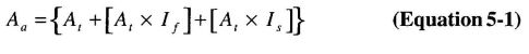
where:
Aa = Allowable building area per story (square feet).
At = Tabular building area per story in accordance with Table 503 (square feet).
If = Area increase factor due to frontage as calculated in accordance with Section 506.2.
Is = Area increase factor due to sprinkler protection as calculated in accordance with Section 506.3.
506.2 Frontage increase. Every building shall adjoin or have access to a public way to receive a building area increase for frontage. Where a building has more than 25 percent of its perimeter on a public way or open space having a minimum width of 20 feet (6096 mm), the frontage increase shall be determined in accordance with the following:

where:
If = Area increase due to frontage.
F = Building perimeter that fronts on a public way or open space having 20 feet (6096 mm) open minimum width (feet).
P = Perimeter of entire building (feet).
W = Width of public way or open space (feet) in accordance with Section 506.2.1.
506.2.1 Width limits. The value of W shall be at least 20 feet (6096 mm). Where the value of W varies along the perimeter of the building, the calculation performed in accordance with Equation 5-2 shall be used on the weighted average of each portion of exterior wall and open space where the value of W is greater than or equal to 20 feet (6096 mm). Where the value of W exceeds 30 feet (9144 mm), a value of 30 feet (9144 mm) shall be used in calculating the weighted average, regardless of the actual width of the open space. Where two or more buildings are on the same lot, W shall be measured from the exterior face of a building to the exterior face of an opposing building, as applicable.
Exception: The value of W divided by 30 shall be permitted to be a maximum of 2 when the building meets all requirements of Section 507 except for compliance with the 60-foot (18 288 mm) public way or yard requirement, as applicable.
506.2.2 Open space limits. Such open space shall be either on the same lot or dedicated for public use and shall be accessed from a street or approved fire lane.
506.3 Automatic sprinkler system increase. Where a building is equipped throughout with an approved automatic sprinkler system in accordance with Section 903.3.1.1, the building area limitation in Table 503 is permitted to be increased by an additional 200 percent (Is = 2) for buildings with more than one story above grade plane and an additional 300 percent (Is = 3) for buildings with no more than one story above grade plane. In other than Group A, E, H, I, L and R occupancies, high-rise buildings, and other applications listed in Section 1.11 regulated by the Office of the State Fire Marshal, these increases are permitted in addition to the height and story increases in accordance with Section 504.2. For Group R-2 buildings of Type VA construction equipped throughout with an approved automatic sprinkler system in accordance with Section 903.3.1.1, these increases are permitted in addition to the height increase in accordance with Section 504.2.
Exception: The building area limitation increases shall not be permitted for the following conditions:
- The automatic sprinkler system increase shall not apply to buildings with an occupancy in Group H-1.
- The automatic sprinkler system increase shall not apply to the building area of an occupancy in Group H-2 or H-3. For buildings containing such occupancies, the allowable building area shall be determined in accordance with Section 508.4.2, with the sprinkler system increase applicable only to the portions of the building not classified as Group H-2 or H-3.
- Fire-resistance rating substitution in accordance with Table 601, Note d.
- [SFM] The automatic sprinkler system increase shall not apply to buildings with an occupancy in Group L.
506.4 Single occupancy buildings with more than one story. The total allowable building area of a single occupancy build
152ing with more than one story above grade plane shall be determined in accordance with this section. The actual aggregate building area at all stories in the building shall not exceed the total allowable building area.
Exception: A single basement need not be included in the total allowable building area, provided such basement does not exceed the area permitted for a building with no more than one story above grade plane.
506.4.1 Area determination. In other than Group A, E, H, I, L and R occupancies, high-rise buildings, and other applications listed in Section 1.11 regulated by the Office of the State Fire Marshal, the total allowable building area of a single occupancy building with more than one story above grade plane shall be determined by multiplying the allowable building area per story (Aa), as determined in Section 506.1, by the number of stories above grade plane as listed below:
Exception: Unlimited area buildings in accordance with Section 507.
For Group A, E, H, I, L and R occupancies, high-rise buildings, and other applications listed in Section 1.11 regulated by the Office of the State Fire Marshal, the total allowable building area of a single occupancy building with more than one story above grade plane shall be determined by multiplying the allowable building area per story (Aa), as determined in Section 506.1, by the number of stories above grade plane as listed below:
Exception: Unlimited area buildings in accordance with Section 507.
506.5 Mixed occupancy area determination. The total allowable building area for buildings containing mixed occupancies shall be determined in accordance with the applicable provisions of this section. A single basement need not be included in the total allowable building area, provided such basement does not exceed the area permitted for a building with no more than one story above grade plane.
506.5.1 No more than one story above grade plane. For buildings with no more than one story above grade plane and containing mixed occupancies, the total building area shall be determined in accordance with the applicable provisions of Section 508.1.
506.5.2 More than one story above grade plane. For buildings with more than one story above grade plane and containing mixed occupancies, each story shall individually comply with the applicable requirements of Section 508.1.
For other than Group A, E, H, I, L and R occupancies, high-rise buildings, and other applications listed in Section 1.11 regulated by the Office of the State Fire Marshal, buildings with more than three stories above grade plane, the total building area shall be such that the aggregate sum of the ratios of the actual area of each story divided by the allowable area of such stories based on the applicable provisions of Section 508.1 shall not exceed 3.
For Group A, E, H, I, L and R occupancies, high-rise buildings, and other applications listed in Section 1.11 regulated by the Office of the State Fire Marshal, buildings with more than two stories above grade plane, the total building area shall be such that the aggregate sum of the ratios of the actual area of each story divided by the allowable area of such stories based on the applicable provisions of Section 508.1 shall not exceed 2.
507.1 General. The area of buildings of the occupancies and configurations specified herein shall not be limited.
507.2 Nonsprinklered, one story. The area of a Group F-2 or S-2 building no more than one story in height shall not be limited when the building is surrounded and adjoined by public ways or yards not less than 60 feet (18 288 mm) in width.
507.3 Sprinklered, one story. The area of a Group B, F, M or S building no more than one story above grade plane shall not be limited when the building is provided with an automatic sprinkler system throughout in accordance with Section 903.3.1.1 and is surrounded and adjoined by public ways or yards not less than 60 feet (18 288 mm) in width.
Exception: Buildings and structures of Types I and II construction for rack storage facilities that do not have access by the public shall not be limited in height, provided that such buildings conform to the requirements of Sections 507.3, 903.3.1.1 and Chapter 23 of the California Fire Code.
507.3.1 Mixed occupancy buildings with Groups A-1 and A-2. Group A-1 and A-2 occupancies of other than Type V construction shall be permitted within mixed occupancy buildings of unlimited area complying with Section 507.3, provided:
507.4 Two story. The area of a Group B, F, M or S building no more than two stories above grade plane shall not be limited when the building is equipped throughout with an automatic sprinkler system in accordance with Section 903.3.1.1, and is surrounded and adjoined by public ways or yards not less than 60 feet (18 288 mm) in width.
507.5 Reduced open space. The public ways or yards of 60 feet (18 288 mm) in width required in Sections 507.2, 507.3, 507.4, 507.6 and 507.11 shall be permitted to be reduced to not less than 40 feet (12 192 mm) in width provided all of the following requirements are met:
507.6 Group A-3 building of Type II construction. The area of a Group A-3 building no more than one story above grade plane, used as a place of religious worship, community hall, dance hall, exhibition hall, gymnasium, lecture hall, indoor swimming pool or tennis court of Type II construction, shall not be limited when all of the following criteria are met:
507.7 Group A-3 buildings of Types III and IV construction. The area of a Group A-3 building no more than one story above grade plane, used as a place of religious worship, community hall, dance hall, exhibition hall, gymnasium, lecture hall, indoor swimming pool or tennis court of Type III or IV construction, shall not be limited when all of the following criteria are met:
507.8 Group H occupancies. Group H-2, H-3 and H-4 occupancies shall be permitted in unlimited area buildings containing Group F and S occupancies, in accordance with Sections 507.3 and 507.4 and the limitations of this section. The aggregate floor area of the Group H occupancies located at the perimeter of the unlimited area building shall not exceed 10 percent of the area of the building nor the area limitations for the Group H occupancies as specified in Table 503 as modified by Section 506.2, based upon the percentage of the perimeter of each Group H floor area that fronts on a street or other unoccupied space. The aggregate floor area of Group H occupancies not located at the perimeter of the building shall not exceed 25 percent of the area limitations for the Group H occupancies as specified in Table 503. Group H occupancies shall be separated from the rest of the unlimited area building and from each other in accordance with Table 508.4. For two-story unlimited area buildings, the Group H occupancies shall not be located more than one story above grade plane unless permitted by the allowable height in stories and feet as set forth in Table 503 based on the type of construction of the unlimited area building.
507.9 Aircraft paint hangar. The area of a Group H-2 aircraft paint hangar no more than one story above grade plane shall not be limited where such aircraft paint hangar complies with the provisions of Section 412.6 and is surrounded and adjoined by public ways or yards not less in width than one and one-half times the building height.
507.10 Group E buildings. The area of a Group E building no more than one story above grade plane, of Type IIA, IIIA or IV construction, shall not be limited when all of the following criteria are met:
507.11 Motion picture theaters. In buildings of Type II construction, the area of a motion picture theater located on the first story above grade plane shall not be limited when the building is provided with an automatic sprinkler system throughout in accordance with Section 903.3.1.1 and is surrounded and adjoined by public ways or yards not less than 60 feet (18 288 mm) in width.
507.12 Covered mall buildings and anchor stores. The area of covered mall buildings and anchor stores not exceeding three stories in height that comply with Section 402.6 shall not be limited.
508.1 General. Each portion of a building shall be individually classified in accordance with Section 302.1. Where a building contains more than one occupancy group, the building or portion thereof shall comply with the applicable provisions of Section 508.2, 508.3 or 508.4, or a combination of these sections.
Exceptions:
508.2 Accessory occupancies. Accessory occupancies are those occupancies that are ancillary to the main occupancy of the building or portion thereof. Accessory occupancies shall comply with the provisions of Sections 508.2.1 through 508.2.5.3.
508.2.1 Area limitations. Aggregate accessory occupancies shall not occupy more than 10 percent of the building area of the story in which they are located and shall not exceed the tabular values in Table 503, without building area increases in accordance with Section 506 for such accessory occupancies.
508.2.2 Occupancy classification. Accessory occupancies shall be individually classified in accordance with Section 302.1. The requirements of this code shall apply to each portion of the building based on the occupancy classification of that space.
508.2.3 Allowable building area and height. The allowable building area and height of the building shall be based on the allowable building area and height for the main occupancy in accordance with Section 503.1. The height of each accessory occupancy shall not exceed the tabular values in Table 503, without increases in accordance with Section 504 for such accessory occupancies. The building area of the accessory occupancies shall be in accordance with Section 508.2.1.
508.2.4 Separation of occupancies. No separation is required between accessory occupancies and the main occupancy.
Exceptions:
- Group H-2, H-3, H-4, H-5, I-2, I2.1, I-3 and L occupancies shall be separated from all other occupancies in accordance with Section 508.4.
- Incidental accessory occupancies required to be separated or protected by Section 508.2.5.
- Group R-1, R-2, R-2.I and R-3 dwelling units and sleeping units shall be separated from other dwelling or sleeping units and from accessory occupancies contiguous to them in accordance with the requirements of Section 420.
508.2.5 Separation of incidental accessory occupancies. The incidental accessory occupancies listed in Table 508.2.5 shall be separated from the remainder of the building or equipped with an automatic fire-extinguishing system, or both, in accordance with Table 508.2.5.
Exception: Incidental accessory occupancies within and serving a dwelling unit are not required to comply with this section.
508.2.5.1 Fire-resistance-rated separation. Where Table 508.2.5 specifies a fire-resistance-rated separation, the incidental accessory occupancies shall be separated from the remainder of the building by a fire barrier constructed in accordance with Section 707 or a horizontal assembly constructed in accordance with Section 712, or both. Construction supporting 1-hour fire-resistance-rated fire barriers or horizontal assemblies used for incidental accessory occupancy separations in buildings of Type IIB, IIIB and VB construction are not required to be fire-resistance rated unless required by other sections of this code.
508.2.5.2 Nonfire-resistance-rated separation and protection. Where Table 508.2.5 permits an automatic fire-extinguishing system without a fire barrier, the incidental accessory occupancies shall be separated from the remainder of the building by construction capable of resisting the passage of smoke. The walls shall extend from the top of the foundation or floor assembly below to the underside of the ceiling that is a component of a fire-resistance-rated floor assembly or roof assembly above or to the underside of the floor or roof sheathing, deck or slab above. Doors shall be self- or automatic closing upon detection of smoke in accordance with Section 715.4.8.3. Doors shall not have air transfer openings and shall not be undercut in excess of the clearance permitted in accordance with NFPA 80. Walls surrounding the incidental accessory occupancy shall not have air transfer openings unless provided with smoke dampers in accordance with Section 711.7.
508.2.5.3 Protection. Except as specified in Table 508.2.5 for certain incidental accessory occupancies, where an automatic fire-extinguishing system or an automatic sprinkler system is provided in accordance with Table 508.2.5, only the space occupied by the incidental accessory occupancy need be equipped with such a system.
508.3 Nonseparated occupancies. Buildings or portions of buildings that comply with the provisions of this section shall be considered as nonseparated occupancies.
508.3.1 Occupancy classification. Nonseparated occupancies shall be individually classified in accordance with Section 302.1. The requirements of this code shall apply to each portion of the building based on the occupancy classification of that space except that the most restrictive applicable provisions of Section 403 and Chapter 9 shall apply to the building or portion thereof in which the nonseparated occupancies are located.
508.3.2 Allowable building area and height. The allowable building area and height of the building or portion thereof shall be based on the most restrictive allowances for the occupancy groups under consideration for the type of construction of the building in accordance with Section 503.1.
508.3.3 Separation. No separation is required between nonseparated occupancies.
155Exceptions:
- Group H-2, H-3, H-4, H-5, I-2, I-2.1, I-3 and L occupancies shall be separated from all other occupancies in accordance with Section 508.4.
- Group R-1, R-2, R-2.1 and R-3 dwelling units and sleeping units shall be separated from other dwelling or sleeping units and from other occupancies contiguous to them in accordance with the requirements of Section 420.
| ROOM OR AREA | SEPARATION AND/OR PROTECTION |
|---|---|
| Furnace room where any piece of equipment is over 400,000 Btu per hour input | 1 hour or provide automatic fire-extinguishing systema |
| Rooms with boilers where the largest piece of equipment is over 15 psi and 10 horsepower | 1 hour or provide automatic fire-extinguishing systema |
| Refrigerant machinery room | 1 hour or provide automatic sprinkler systema |
| Hydrogen cutoff rooms, not classified as Group H | 1 hour in Group B, F, M, S and U occupancies; 2 hours in Group A, E, I and R occupancies. |
| Incinerator rooms | 2 hours and automatic sprinkler system |
| Paint shops, not classified as Group H, located in occupancies other than Group F | 2 hours; or 1 hour and provide automatic fire-extinguishing system |
| Laboratories and vocational shops, not classified as Group H, located in a Group I-2 and I-2,1 occupancy | 1 hour or provide automatic fire-extinguishing systema |
| [SFM] Rooms or areas with special hazards such as laboratories, vocational shops and other such areas not classified as Group H, located in Group E occupancies where hazardous materials in quantities not exceeding the maximum allowable quantity are used or stored. | 1 hour |
| Laundry rooms over 100 square feet | 1 hour or provide automatic fire-extinguishing systema |
| Storage rooms over 100 square feet | 1 hour or provide automatic fire-extinguishing systema |
| Group I-2 and I-2.1 waste and linen collection rooms | 1 houra |
| Waste and linen collection rooms over 100 square feet | 1 hour or provide automatic fire-extinguishing systema |
| Stationary storage battery systems having a liquid electrolyte capacity of more than 50 gallons, or a lithium-ion capacity of 1,000 pounds used for facility standby power, emergency power or uninterrupted power supplies | 1 hour in Group B, F, M, S and U occupancies; 2 hours in Group A, E, I and R occupancies.a |
| Rooms containing fire pumps in nonhigh-rise buildings | 2 hours; or 1 hour and provide automatic sprinkler system throughout the building |
| Rooms containing fire pumps in high-rise buildings | 2 hours |
| For SI: 1 square foot = 0.0929m2, 1 pound per square inch (psi) = 6.9 kPa, 1 British thermal unit (Btu) per hour = 0.293 watts, 1 horsepower = 746 watts, 1 gallon = 3.785 L. | |
| a. [SFM] Fire barrier protection and automatic sprinkler protection required throughout the fire area in I-2 and I-2.1 occupancies as indicated. | |
508.4 Separated occupancies. Buildings or portions of buildings that comply with the provisions of this section shall be considered as separated occupancies.
508.4.1 Occupancy classification. Separated occupancies shall be individually classified in accordance with Section 302.1. Each separated space shall comply with this code based on the occupancy classification of that portion of the building.
508.4.2 Allowable building area. In each story, the building area shall be such that the sum of the ratios of the actual building area of each separated occupancy divided by the allowable building area of each separated occupancy shall not exceed 1.
508.4.3 Allowable height. Each separated occupancy shall comply with the building height limitations based on the type of construction of the building in accordance with Section 503.1.
Exception: Special provisions permitted by Section 509.
508.4.4 Separation. Individual occupancies shall be separated from adjacent occupancies in accordance with Table 508.4.
508.4.4.1 Construction. Required separations shall be fire barriers constructed in accordance with Section 707 or horizontal assemblies constructed in accordance with Section 712, or both, so as to completely separate adjacent occupancies.
509.1 General. The provisions in this section shall permit the use of special conditions that are exempt from, or modify, the specific requirements of this chapter regarding the allowable heights and areas of buildings based on the occupancy classification and type of construction, provided the special condition complies with the provisions specified in this section for such condition and other applicable requirements of this code. The provisions of Sections 509.2 through 509.8 are to be considered independent and separate from each other.
156| OCCUPANY | Ad,E | I-4,R-2.1 | I-2, I-2.1 | I-3 | R-1, R-2, R-3, R-3.1, R-4 | F-2, S-2b, U | B, F-1g, M, S-1 | L | H-1 | H-2 | H-3, H-4, H-5 | |||||||||||
|---|---|---|---|---|---|---|---|---|---|---|---|---|---|---|---|---|---|---|---|---|---|---|
| S | NS | S | NS | S | NS | S | NS | S | NS | S | NS | S | NS | S | NS | S | NS | S | NS | S | NS | |
| Ad,E | N | N | 2 | 2 | 2 | NP | 2 | NP | 1 | 2 | N | 1 | 1 | 2 | 2 | NP | NP | NP | 3 | 4 | 2 | 3a |
| I-4, R-2.1 | — | — | 1e | NP | 2 | NP | 2 | NP | 1 | NP | 2 | 2 | 2f | 2 | 2 | NP | NP | NP | 4 | NP | 4 | NP |
| I-2, I-2.1 | — | — | — | — | N | NP | 2 | NP | 2 | NP | 2 | NP | 2f | NP | 2 | NP | NP | NP | 4 | NP | 4 | NP |
| I-3 | — | — | — | — | — | — | N | NP | 2 | NP | 2 | 2 | 2 | 2 | 2 | NP | NP | NP | 4 | NP | 4 | NP |
| R-1, R-2, R-3, R-3.1, R-4 | N | N | 1c | 2c | 1 | 2 | 4 | NP | NP | NP | 3 | NP | 2 | NP | ||||||||
| F-2, S-2b, U | — | — | — | — | — | — | — | — | N | N | 1 | 2 | 1 | NP | NP | NP | 3 | 4 | 2 | 3a | ||
| B, F-1, M, S-1 | — | — | — | — | — | — | — | — | — | — | N | N | 1 | NP | NP | NP | 2 | 3 | 1 | 2a | ||
| L | 1 | NP | NP | NP | 2 | NP | 1 | NP | ||||||||||||||
| H-1 | — | — | — | — | — | — | — | — | — | — | — | — | N | NP | NP | NP | NP | NP | ||||
| H-2 | — | — | — | — | — | — | — | — | — | — | — | — | — | — | N | NP | 1 | NP | ||||
| H-3, H-4, H-5 | — | — | — | — | — | — | — | — | — | — | — | — | — | — | — | — | 1e, f | NP | ||||
| For SI: 1 square foot = 0.0929 m2. | ||||||||||||||||||||||
| S = Buildings equipped throughout with an automatic sprinkler system installed in accordance with Section 903.3.1.1. | ||||||||||||||||||||||
| NS = Buildings not equipped throughout with an automatic sprinkler system installed in accordance with Section 903.3.1.1. | ||||||||||||||||||||||
| N = No separation requirement. | ||||||||||||||||||||||
| NP = Not permitted. | ||||||||||||||||||||||
| a. For Group H-5 occupancies, see Section 903.2.5.2. | ||||||||||||||||||||||
| b. The required separation from areas used only for private or pleasure vehicles shall be reduced by 1 hour but to not less than 1 hour. | ||||||||||||||||||||||
| c. See Section 406.1.4. | ||||||||||||||||||||||
| d. Commercial kitchens need not be separated from the restaurant seating areas that they serve. | ||||||||||||||||||||||
| e. Separation is not required between occupancies of the same classification. | ||||||||||||||||||||||
| f. For H-5 occupancies, see Section 415.8.2.2. | ||||||||||||||||||||||
| g. [SFM] Group I and F1 occupancies and Group R-2.1 and F-1 occupancies shall have a 3-hour separation. | ||||||||||||||||||||||
509.2 Horizontal building separation allowance. A building shall be considered as separate and distinct buildings for the purpose of determining area limitations, continuity of fire walls, limitation of number of stories and type of construction where all of the following conditions are met:
Exception: Where the enclosure walls below the horizontal assembly have not less than a 3-hour fire-resistance rating with opening protectives in accordance with Section 715.4, the enclosure walls extending above the horizontal assembly shall be permitted to have a 1-hour fire-resistance rating, provided:
509.3 Group S-2 enclosed parking garage with Group S-2 open parking garage above. A Group S-2 enclosed parking garage with no more than one story above grade plane and located below a Group S-2 open parking garage shall be classified as a separate and distinct building for the purpose of determining the type of construction where all of the following conditions are met:
509.4 Parking beneath Group R. Where a maximum one story above grade plane Group S-2 parking garage, enclosed or open, or combination thereof, of Type I construction or open of Type IV construction, with grade entrance, is provided under a building of Group R, the number of stories to be used in determining the minimum type of construction shall be measured from the floor above such a parking area. The floor assembly between the parking garage and the Group R above shall comply with the type of construction required for the parking garage and shall also provide a fire-resistance rating not less than the mixed occupancy separation required in Section 508.4.
509.5 Group R-1 and R-2 buildings of Type IIIA construction. The height limitation for buildings of Type IIIA construction in Groups R-1 and R-2 shall be increased to six stories and 75 feet (22 860 mm) where the first floor assembly above the basement has a fire-resistance rating of not less than 3 hours and the floor area is subdivided by 2-hour fire-resistance-rated fire walls into areas of not more than 3,000 square feet (279 m2).
509.6 Group R-1 and R-2 buildings of Type IIA construction. The height limitation for buildings of Type IIA construction in Groups R-1 and R-2 shall be increased to nine stories and 100 feet (30 480 mm) where the building is separated by not less than 50 feet (15 240 mm) from any other building on the lot and from lot lines, the exits are segregated in an area enclosed by a 2-hour fire-resistance-rated fire wall and the first floor assembly has a fire-resistance rating of not less than 1½ hours.
509.7 Open parking garage beneath Groups A, I, B, M and R. Open parking garages constructed under Groups A, I, B, M and R shall not exceed the height and area limitations permitted under Section 406.3. The height and area of the portion of the building above the open parking garage shall not exceed the limitations in Section 503 for the upper occupancy. The height, in both feet and stories, of the portion of the building above the open parking garage shall be measured from grade plane and shall include both the open parking garage and the portion of the building above the parking garage.
509.7.1 Fire separation. Fire barriers constructed in accordance with Section 707 or horizontal assemblies constructed in accordance with Section 712 between the parking occupancy and the upper occupancy shall correspond to the required fire-resistance rating prescribed in Table 508.4 for the uses involved. The type of construction shall apply to each occupancy individually, except that structural members, including main bracing within the open parking structure, which is necessary to support the upper occupancy, shall be protected with the more restrictive fire-resistance-rated assemblies of the groups involved as shown in Table 601. Means of egress for the upper occupancy shall conform to Chapter 10 and shall be separated from the parking occupancy by fire barriers having at least a 2-hour fire-resistance rating as required by Section 706 with self-closing doors complying with Section 715 or horizontal assemblies having at least a 2-hour fire-resistance rating as required by Section 712, with self-closing doors complying with Section 715. Means of egress from the open parking garage shall comply with Section 406.3.
509.8 Group B or M with Group S-2 open parking garage. Group B or M occupancies located no higher than the first story above grade plane shall be considered as a separate and distinct building for the purpose of determining the type of construction where all of the following conditions are met:
509.9 Multiple buildings above Group S-2 parking garages. Where two or more buildings are provided above the horizontal assembly separating a Group S-2 open or closed parking garage from the buildings above in accordance with the special provisions in Sections 509.2, 509.3 or 509.8, the buildings above the horizontal assembly shall be regarded as separate and distinct buildings from each other and shall comply with all other provisions of this code as applicable to each separate and distinct building.
509.10 Group R. [SFM] Buildings housing protective socialcare homes or in occupancies housing inmates who are not restrained need not be of one-hour fire-resistive construction when not more than two stories in height. In no case shall individual floor areas exceed 3,000 square feet (279 m2). The fire-resistive protection of the exterior walls shall not be less than one hour where such walls are located within 5 feet (1524 mm) of the property line. Openings within such walls are not permitted. Openings in exterior nonrated walls need not be protected.
159 160| Adopting agency | BSC | SFM | HCD | DSA | OSHPD | CSA | DPH | AGR | DWR | CEC | CA | SL | SLC | |||||||
|---|---|---|---|---|---|---|---|---|---|---|---|---|---|---|---|---|---|---|---|---|
| 1 | 2 | 1-AC | AC | SS | SS/CC | 1 | 2 | 3 | 4 | |||||||||||
| Adopt entire chapter | X | X | X | X | X | X | X | |||||||||||||
| Adopt entire chapter as amended (amended sections listed below) | X | X | X | |||||||||||||||||
| Adopt only those sections that are listed below | ||||||||||||||||||||
| Chapter/Section | ||||||||||||||||||||
| Table 601 | X | |||||||||||||||||||
| Table 602 | X | X | ||||||||||||||||||
| 603.1 | X | X | ||||||||||||||||||
| The Office of the State Fire Marshal's adoption of this chapter or individual sections is applicable to structures regulated by other state agencies pursuant to Section 1.11. | ||||||||||||||||||||
601.1 Scope. The provisions of this chapter shall control the classification of buildings as to type of construction.
602.1General. Buildings and structures erected or to be erected, altered or extended in height or area shall be classified in one of the five construction types defined in Sections 602.2 through 602.5. The building elements shall have a fire-resistance rating not less than that specified in Table 601 and exterior walls shall have a fire-resistance rating not less than that specified in Table 602.Where required to have a fire-resistance rating by Table 601, building elements shall comply with the applicable provisions of Section 703.2. The protection of openings, ducts and air transfer openings in building elements shall not be required unless required by other provisions of this code.
602.1.1 Minimum requirements. A building or portion thereof shall not be required to conform to the details of a type of construction higher than that type which meets the minimum requirements based on occupancy even though certain features of such a building actually conform to a higher type of construction.
602.2 Types I and II. Types I and II construction are those types of construction in which the building elements listed in Table 601 are of noncombustible materials, except as permitted in Section 603 and elsewhere in this code.
602.3 Type III. Type III construction is that type of construction in which the exterior walls are of noncombustible materials and the interior building elements are of any material permitted by this code.Fire-retardant-treated wood framing complying with Section 2303.2 shall be permitted within exterior wall assemblies of a 2-hour rating or less.
| BUILDING ELEMENT | TYPE I | TYPE II | TYPE III | TYPE IV | TYPE V | ||||
|---|---|---|---|---|---|---|---|---|---|
| A | B | Ad | B | Ad | B | HT | Ad | B | |
| Primary structural frameg (see Section 202) | 3a | 2a | 1 | 0 | 1 | 0 | HT | 1 | 0 |
| Bearing walls Exteriorf,g Interior | 3 3a | 2 2a | 1 1 | 0 0 | 2 1 | 2 0 | 2 1/HT | 1 1 | 0 0 |
| Nonbearing walls and partitions Exterior | See Table 602 | ||||||||
| Nonbearing walls and partitions Interiore | 0 | 0 | 0 | 0 | 0 | 0 | See Section 602.4.6 | 0 | 0 |
| Floor construction and secondary members (see Section 202) | 2 | 2 | 1 | 0 | 1 | 0 | HT | 1 | 0 |
| Roof construction and secondary members (see Section 202) | 1 1/2b | 1b,c | 1b,c | 0c | 1b,c | 0 | HT | 1b,c | 0 |
| For SI: 1 foot=304.8mm. | |||||||||
| a.Roof supports: Fire-resistance ratings of primary structural frame and bearing walls are permitted to be reduced by 1 hour where supporting a roof only. | |||||||||
| b1. Except in Group A, E, F-1, H, I, L, M, R-1, R-2, R-2.1 and S-1 occupancies, high-rise buildings, and other applications listed in Section 1.11 regulated by the Office of the State Fire Marshal,fire protection of structural members shall not be required, including protection of roof framing and decking where every part of the roof construction is 20 feet or more above any floor immediately below. Fire-retardant-treated wood members shall be allowed to be used for such unprotected members. | |||||||||
| b2.For Group A, E, I, L, R-1, R-2, and R-2.1 occupancies, high-rise buildings, and other applications listed in Section 1.11 regulated by the Office of the State Fire Marshal, fire protection of members other than the structural frame shall not be required, including protection of roof framing and decking where every part of the roof construction is 20 feet or more above any floor immediately below. Fire-retardant-treated wood members shall be allowed to be used for such unprotected members. | |||||||||
| b3.One-story portions of Group A and E assembly occupancies the roof-framing system of Type II A or Type III A construction may be of unprotected construction when such roof-framing system is open to the assembly area and does not contain concealed spaces. | |||||||||
| c. In all occupancies, heavy timber shall be allowed where a 1-hour or less fire-resistance rating is required. | |||||||||
| d. An approved automatic sprinkler system in accordance with Section 903.3.1.1 shall be allowed to be substituted for 1-hour fire-resistance-rated construction, provided such system is not otherwise required by other provisions of the code or used for an allowable area increase in accordance with Section 506.3 or an allowable height increase in accordance with Section 504.2. The 1-hour substitution for the fire resistance of exterior walls shall not be permitted. | |||||||||
| e. Not less than the fire-resistance rating required by other sections of this code. | |||||||||
| f. Not less than the fire-resistance rating based on fire separation distance (see Table 602). | |||||||||
| g. Not less than the fire-resistance rating as referenced in Section 704.10 | |||||||||
602.4 Type IV. Type IV construction (Heavy Timber, HT) is that type of construction in which the exterior walls are of noncombustible materials and the interior building elements are of solid or laminated wood without concealed spaces. The details of Type IV construction shall comply with the provisions of this section. Fire-retardant-treated wood framing complying with Section 2303.2 shall be permitted within exterior wall assemblies with a 2-hour rating or less.Minimum solid sawn nominal dimensions are required for structures built using Type IV construction (HT). For glued-laminated members the equivalent net finished width and depths corresponding to the minimum nominal width and depths of solid sawn lumber are required as specified in Table 602.4.
602.4.1 Columns. Wood columns shall be sawn or glued laminated and shall not be less than 8 inches (203 mm), nominal, in any dimension where supporting floor loads and not less than 6 inches (152 mm) nominal in width and not less than 8 inches (203 mm) nominal in depth where supporting roof and ceiling loads only. Columns shall be continuous or superimposed and connected in an approved manner.
602.4.2 Floor framing. Wood beams and girders shall be of sawn or glued-laminated timber and shall be not less than 6 inches (152 mm) nominal in width and not less than 10 inches (254 mm) nominal in depth. Framed sawn or glued-laminated timber arches, which spring from the floor line and support floor loads, shall be not less than 8 inches (203 mm) nominal in any dimension. Framed timber trusses supporting floor loads shall have members of not less than 8 inches (203 mm) nominal in any dimension.
602.4.3 Roof framing. Wood-frame or glued-laminated arches for roof construction, which spring from the floor line or from grade and do not support floor loads, shall have members not less than 6 inches (152 mm) nominal in width and have not less than 8 inches (203 mm) nominal in depth for the lower half of the height and not less than 6 inches (152 mm) nominal in depth for the upper half. Framed or glued-laminated arches for roof construction that spring
| FIRE SEPARATION DISTANCE = X (feet) | TYPE OF CONSTRUCTION | OCCUPANCY GROUP Hf, L | OCCUPANCY GROUP F-1, M, S-1 | OCCUPANCY GROUP A, B, E, F-2, I, Rh, S-2g, Ub,h |
|---|---|---|---|---|
| x < 5c | All | 3 | 2 | 1 |
| 5 ≤X <10 | IA Others | 3 2 | 2 1 | 1 1 |
| 10 ≤ X < 30 | IA,IB IIB,VB Others | 2 1 1 | 1 0 1 | 1d 0 1d |
| X ≥ 30 | All | 0 | 0 | 0 |
| For SI: 1 foot = 304.8 mm. | ||||
| a. Load-bearing exterior walls shall also comply with the fire-resistance rating requirements of Table 601. | ||||
| b. For special requirements for Group U occupancies, see Section 406.1.2. | ||||
| c. See Section 706.1.1 for party walls. | ||||
| d. Open parking garages complying with Section 406 shall not be required to have a fire-resistance rating. | ||||
| e.The fire-resistance rating of an exterior wall is determined based upon the fire separation distance of the exterior wall and the story in which the wall is located. | ||||
| f. For special requirements for Group H occupancies, see Section 415.3. | ||||
| g. For special requirements for Group S aircraft hangars, see Section 412.4.1. | ||||
| h. Group R-3 and Group U occupancies when used as accessory to Group R-3 occupancies, shall not be required to have a fire-resistance rating where the fire separation distance is 5 feet or more; or when equipped throughout with an automatic residential fire sprinkler system installed in accordance with Section 903.3 the fire-resistance rating shall not be required where the fire separation distance is 3 feet or more. | ||||
| MINIMUM NOMINAL SOLID SAWN SIZE | MINIMUM GLUED-LAMINATED NET SIZE | ||
|---|---|---|---|
| Width,inch | Depth,inch | Width,inch | Depth,inch |
| 8 | 8 | 6 ¾ | 8 ¼ |
| 6 | 10 | 5 | 10½ |
| 6 | 8 | 5 | 8 ¼ |
| 6 | 6 | 5 | 6 |
| 4 | 6 | 3 | 6 7/8 |
| For SI: 1 inch = 25.4 mm. | |||
from the top of walls or wall abutments, framed timber trusses and other roof framing, which do not support floor loads, shall have members not less than 4 inches (102 mm) nominal in width and not less than 6 inches (152 mm) nominal in depth. Spaced members shall be permitted to be composed of two or more pieces not less than 3 inches (76 mm) nominal in thickness where blocked solidly throughout their intervening spaces or where spaces are tightly closed by a continuous wood cover plate of not less than 2 inches (51 mm) nominal in thickness secured to the underside of the members. Splice plates shall be not less than 3 inches (76 mm) nominal in thickness. Where protected by approved automatic sprinklers under the roof deck, framing members shall be not less than 3 inches (76 mm) nominal in width.
602.4.4 Floors. Floors shall be without concealed spaces. Wood floors shall be of sawn or glued-laminated planks, splined or tongue-and-groove, of not less than 3 inches (76 mm) nominal in thickness covered with 1-inch (25 mm) nominal dimension tongue-and-groove flooring, laid crosswise or diagonally, or 0.5-inch (12.7 mm) particleboard or planks not less than 4 inches (102 mm) nominal in width set on edge close together and well spiked and covered with 1-inch (25 mm) nominal dimension flooring or 15/32-inch (12 mm) wood structural panel or 0.5-inch (12.7 mm) particleboard. The lumber shall be laid so that no continuous line of joints will occur except at points of support. Floors shall not extend closer than 0.5 inch (12.7 mm) to walls. Such 0.5-inch (12.7 mm) space shall be covered by a molding fastened to the wall and so arranged that it will not obstruct the swelling or shrinkage movements of the floor. Corbeling of masonry walls under the floor shall be permitted to be used in place of molding.
602.4.5 Roofs. Roofs shall be without concealed spaces and wood roof decks shall be sawn or glued laminated, splined or tongue-and-groove plank, not less than 2 inches (51 mm) nominal in thickness, 1/8 inch-thick (32 mm) wood structural panel (exterior glue), or of planks not less than 3 inches (76 mm) nominal in width, set on edge close together and laid as required for floors. Other types of decking shall be permitted to be used if providing equivalent fire resistance and structural properties.
602.4.6 Partitions. Partitions shall be of solid wood construction formed by not less than two layers of 1-inch (25 mm) matched boards or laminated construction 4 inches (102 mm) thick, or of 1-hour fire-resistance-rated construction.
602.4.7 Exterior structural members. Where a horizontal separation of 20 feet (6096 mm) or more is provided, wood columns and arches conforming to heavy timber sizes shall be permitted to be used externally.
602.5 Type V. Type V construction is that type of construction in which the structural elements, exterior walls and interior walls are of any materials permitted by this code.
603.1 Allowable materials. Combustible materials shall be permitted in buildings of Type I or II construction in the following applications and in accordance with Sections 603.1.1 through 603.1.3:
Exceptions:
- Insulation placed between two layers of noncombustible materials without an intervening airspace shall be allowed to have a flame spread index of not more than 100.
- Insulation installed between a finished floor and solid decking without intervening airspace shall be allowed to have a flame spread index of not more than 200.
Exception: In buildings of Type IA construction exceeding two stories above grade plane, fire-retardant-treated wood is not permitted in roof construction when the vertical distance from the upper floor to the roof is less than 20 feet (6096 mm).
603.1.1 Ducts. The use of nonmetallic ducts shall be permitted when installed in accordance with the limitations of the California Mechanical Code.
603.1.2 Piping. The use of combustible piping materials shall be permitted when installed in accordance with the limitations of the California Mechanical Code and the California Plumbing Code.
603.1.3 Electrical. The use of electrical wiring methods with combustible insulation, tubing, raceways and related components shall be permitted When installed in accordance with the limitations of the California Electrical Code.
| Adopting agency | BSC | SFM | HCD | DSA | OSHPD | CSA | DPH | AGR | DWR | EC | CA | SL | SLC | |||||||
|---|---|---|---|---|---|---|---|---|---|---|---|---|---|---|---|---|---|---|---|---|
| 1 | 2 | 1-AC | AC | SS | SS/CC | 1 | 2 | 3 | 4 | |||||||||||
| Adopt entire chapter | X | X | X | X | X | X | X | |||||||||||||
| Adopt entire chapter as amended (amended sections listed below) | X | X | X | |||||||||||||||||
| Adopt only those sections that are listed below | ||||||||||||||||||||
| Chapter/Section | ||||||||||||||||||||
| 702.1 | X | |||||||||||||||||||
| Fire-smoke Barrier | X | |||||||||||||||||||
| 705.2.3 | X | |||||||||||||||||||
| 705.5 | X | |||||||||||||||||||
| 705.8.5 | X | |||||||||||||||||||
| Table 706.3.9 | X | |||||||||||||||||||
| Table 706.4 | X | |||||||||||||||||||
| Table 707.3.9 | X | |||||||||||||||||||
| 708.2 | X | |||||||||||||||||||
| 708.14.1 | X | |||||||||||||||||||
| 709.1 | X | |||||||||||||||||||
| 709.4 | X | |||||||||||||||||||
| 710.5 | X | |||||||||||||||||||
| 711.2 | X | |||||||||||||||||||
| 711.7 | X | |||||||||||||||||||
| 715.4.3 | X | |||||||||||||||||||
| 715.4.4 | X | |||||||||||||||||||
| 715.4.4.1 | X | |||||||||||||||||||
| 715.4.6.1 | X | |||||||||||||||||||
| 715.4.7.3 | X | |||||||||||||||||||
| 715.4.8.3 | X | |||||||||||||||||||
| 716.2.2 | X | |||||||||||||||||||
| 716.5.2 | X | |||||||||||||||||||
| 716.5.4 | X | X | X | X | X | |||||||||||||||
| 716.5.4.1 | X | |||||||||||||||||||
| 716.6.1 | X | |||||||||||||||||||
| 716.6.2 | X | |||||||||||||||||||
| 716.6.3 | X | |||||||||||||||||||
| 717.3.3 | X | |||||||||||||||||||
| 717.4.3 | X | |||||||||||||||||||
| 717.5 | X | |||||||||||||||||||
| 719.1 | X | |||||||||||||||||||
| 719.7 | X | |||||||||||||||||||
| 720.2 | X | X | ||||||||||||||||||
| 720.2.1 | X | X | ||||||||||||||||||
| The Office of the State Fire Marshal's adoption of this chapter or individual sections is applicable to structures regulated by other state agencies pursuant to Section 1.11. | ||||||||||||||||||||
701.1 Scope. The provisions of this chapter shall govern the materials, systems and assemblies used for structural fire resistance and fire-resistance-rated construction separation of adjacent spaces to safeguard against the spread of fire and smoke within a building and the spread of fire to or from buildings.
702.1 Definitions. The following words and terms shall, for the purposes of this chapter, and as used elsewhere in this code, have the meanings shown herein.
ANNULAR SPACE. The opening around the penetrating item.
BUILDING ELEMENT. A fundamental component of building construction, listed in Table 601, which may or may not be of fire-resistance-rated construction and is constructed of materials based on the building type of construction.
CEILING RADIATION DAMPER. A listed device installed in a ceiling membrane of a fire-resistance-rated floor/ceiling or roof/ceiling assembly to limit automatically the radiative heat transfer through an air inlet/outlet opening.
COMBINATION FIRE/SMOKE DAMPER. A listed device installed in ducts and air transfer openings designed to close automatically upon the detection of heat and resist the passage of flame and smoke. The device is installed to operate automatically, controlled by a smoke detection system, and where required, is capable of being positioned from a fire command center.
DAMPER. See “Ceiling radiation damper,” “Combination fire/smoke damper,” “Fire damper” and “Smoke damper.”
DRAFTSTOP. A material, device or construction installed to restrict the movement of air within open spaces off concealed areas of building components such as crawl spaces, floor/ceiling assemblies, roof/ceiling assemblies and attics.
F RATING. The time period that the through-penetration firestop system limits the spread of fire through the penetration when tested in accordance with ASTM E 814 or UL 1479.
FIRE BARRIER. A fire-resistance-rated wall assembly of materials designed to restrict the spread of fire in which continuity is maintained.
FIRE DAMPER. A listed device installed in ducts and air transfer opening designed to close automatically upon detection of heat and resist the passage of flame. Fire dampers are classified for use in either static system that will automatically shut down in the event of a fire, or in dynamic systems that continue to operate during a fire. A dynamic fire damper is tested and rated for closure under elevated temperature airflow.
FIRE DOOR. The door component of a fire door assembly.
FIRE DOOR ASSEMBLY. Any combination of a fire door, frame, hardware and other accessories that together provide a specific degree of fire protection to the opening.
FIRE PARTITION. A vertical assembly of materials designed to restrict the spread of fire in which openings are protected.
FIRE PROTECTION RATING. The period of time that an opening protective will maintain the ability to confine a fire as determined by tests prescribed in Section 715. Ratings are stated in hours or minutes.
FIRE RESISTANCE. That property of materials or their assemblies that prevents or retards the passage of excessive heat, hot gases or flames under conditions of use.
FIRE-RESISTANCE RATING. The period of time a building element, component or assembly maintains the ability to confine a fire, continues to perform a given structural function or both, as determined by the tests, or the methods based on tests, prescribed in Section 703.
FIRE-RESISTANT JOINT SYSTEM. An assemblage of specific materials or products that are designed, tested and fire-resistance rated in accordance with either ASTME 1966 or UL 2079 to resist for a prescribed period of time the passage of fire through joints made in or between fire-resistance-rated assemblies.
FIRE SEPARATION DISTANCE. The distance measured from the building face to one of the following:
The distance shall be measured at right angles from the face of the wall.
FIRE-SMOKE BARRIER. A fire-resistance-rated wall assembly of materials designed to restrict the spread of fire in which continuity is maintained in accordance with Section 707 and that is designed and constructed to restrict the movement of smoke in accordance with Section 710.
FIRE WALL. A fire-resistance-rated wall having protected openings, which restricts the spread of fire and extends continuously from the foundation to or through the roof, with sufficient structural stability under fire conditions to allow collapse of construction on either side without collapse of the wall.
FIRE WINDOW ASSEMBLY. A window constructed and glazed to give protection against the passage of fire.
FIREBLOCKING. Building materials or materials for use as fireblocking, installed to resist the free passage of flame to other areas of the building through concealed spaces.
169FLOOR FIRE DOOR ASSEMBLY. A combination of a fire door, a frame, hardware and other accessories installed in a horizontal plane, which together provide a specific degree of fire protection to a through-opening in a fire-resistance-rated floor (see Section 712.8).
HORIZONTAL ASSEMBLY. A fire-resistance-rated floor or roof assembly of materials designed to restrict the spread of fire in which continuity is maintained.
JOINT. The linear opening in or between adjacent fire-resistance-rated assemblies that is designed to allow independent movement of the building in any plane caused by thermal, seismic, wind or any other loading.
MEMBRANE PENETRATION. An opening made through one side (all, floor or ceiling membrane) of an assembly.
MEMBRANE-PENETRATION FIRESTOP. A material, device or construction installed to resist for a prescribed time period the passage of flame and heat through openings in a protective membrane in order to accommodate cables, cable trays, conduit, tubing, pipes or similar items.
MINERAL FIBER. Insulation composed principally of fibers manufactured from rock, slag or glass, with or without binders.
MINERAL WOOL. Synthetic vitreous fiber insulation made by melting predominately igneous rock or furnace slag, and other inorganic materials, and then physically forming the melt into fibers.
PENETRATION FIRESTOP. A through-penetration firestop or a membrane-penetration firestop.
SELF-CLOSING. As applied to a fire door or other opening protective, means equipped with an device that will ensure closing after having been opened.
SHAFT. An enclosed space extending through one or more stories of a building, connecting vertical openings in successive floors, or floors and roof.
SHAFT ENCLOSURE. The walls or construction forming the boundaries of a shaft.
SMOKE BARRIER. A continous membrane, either vertical or horizontal, such as a wall, floor or ceiling assembly, that is designed and constructed to restrict the movement of smoke.
SMOKE COMPARTMENT. A space within a building enclosed by smoke barriers on all sides, including the top and bottom.
SMOKE DAMPER. A listed device installed in ducts and air transfer openings designed to resist the passage of smoke. The device is installed to operate automatically, controlled by a smoke detection system, and where required, is capable of being positioned from a fire command center.
SPLICE. The result of a factory and/or field method of joining or connecting two or more lengths of a fire-resistant joint system into a continuous entity.
T RATING. The time period that the penetration firestop system, including the penetrating item, limits the maximum temperature rise to 325°F (163°C) above its initial temperature through the penetration on the nonfire side when tested in accordance with ASTM E 814 or UL 1479.
THROUGH PENETRATION. An opening that passes through an entire assembly.
THROUGH-PENETRATION FIRESTOP SYSTEM. An assemblage of specific materials or products that are designed, tested and fire-resistance rated to resist for a prescribed period of time the spread of fire through penetrations. The F and T rating criteria for penetration firestop systems shall be in accordance with ASTM E 814 or UL 1479. See definitions of “F rating” and “ T rating.”
703.1 Scope. Materials prescribed herein for fire resistance shall conform to the requirements of this chapter.
703.2 Fire-resistance ratings. The fire-resistance rating of building elements, components or assemblies shall be determined in accordance with the test procedures set forth in ASTM E 119 or UL 263 or in accordance with Section 703.3. Where materials, systems or devices that have not been tested as part of a fire-resistance-rated assembly are incorporated into the building element, component or assembly, sufficient data shall be made available to the building official to show that the required fire-resistance rating is not reduced. Materials and methods of construction used to protect joints and penetrations in fire-resistance-rated building elements, components or assemblies shall not reduce the required fire-resistance rating.
Exception: In determining the fire-resistance rating of exterior bearing walls, compliance with the ASTM E 119 or UL 263 criteria for unexposed surface temperature rise and ignition of cotton waste due to passage of flame or gases is required only for a period of time corresponding to the required fire-resistance rating of an exterior nonbearing wall with the same fire separation distance, and in a building of the same group. When the fire-resistance rating determined in accordance with this exception exceeds the fire-resistance rating determined in accordance with ASTM E 119 or UL 263, the fire exposure time period, water pressure and application duration criteria for the hose stream test of ASTM E 119 or UL 263 shall be based upon the fire-resistance rating determined in accordance with this exception.
703.2.1 Nonsymmetrical wall construction. Interior walls and partitions of nonsymmetrical construction shall be tested with both faces exposed to the furnace, and the assigned fire-resistance rating shall be the shortest duration obtained from the two tests conducted in compliance with ASTM E 119 or UL 263. When evidence is furnished to show that the wall was tested with the least fire-resistant side exposed to the furnace, subject to acceptance of the building official, the wall need not be subjected to tests from the opposite side (see Section 705.5 for exterior walls).
703.2.2 Combustible components. Combustible aggregates are permitted in gypsum and portland cement concrete mixtures for fire-resistance-rated construction. Any component material or admixture is permitted in assemblies if the resulting tested assembly meets the fire-resistance test requirements of this code.
170703.2.3 Restrained classification. Fire-resistance-rated assemblies tested under ASTME 119 or UL 263 shall not be considered to be restrained unless evidence satisfactory to the building official is furnished by the registered design professional showing that the construction qualifies for a restrained classification in accordance with ASTM E 119 or UL 263. Restrained construction shall be identified on the plans.
703.3 Alternative methods for determining fire resistance. The application of any of the alternative methods listed in this section shall be based on the fire exposure and acceptance criteria specified in ASTM E 119 or UL 263. The required fire resistance of a building element, component or assembly shall be permitted to be established by any of the following methods or procedures:
703.4 Noncombustibility tests. The tests indicated in Sections 703.4.1 and 703.4.2 shall serve as criteria for acceptance of building materials as set forth in Sections 602.2, 602.3 and 602.4 in Type I, II, III and IV construction. The term “noncombustible” does not apply to the flame spread characteristics of interior finish or trim materials. A material shall not be classified as a noncombustible building construction material if it is subject to an increase in combustibility or flame spread beyond the limitations herein established through the effects of age, moisture or other atmospheric conditions.
703.4.1 Elementary materials. Materials required to be noncombustible shall be tested in accordance with ASTM E 136.
703.4.2 Composite materials. Materials having a structural base of noncombustible material as determined in accordance with Section 703.4.1 with a surfacing not more than 0.125 inch (3.18 mm) thick that has a flame spread index not greater than 50 when tested in accordance with ASTM E 84 or UL 723 shall be acceptable as noncombustible materials.
703.5 Fire-resistance-rated glazing. Fire-resistance-rated glazing, when tested in accordance with ASTM E 119 or UL 263 and complying with the requirements of Section 707, shall be permitted. Fire-resistance-rated glazing shall bear a label or other identification showing the name of the manufacturer, the test standard and the identifier “W-XXX,” where the “XXX” is the fire-resistance rating in minutes. Such label or identification shall be issued by an agency and shall be permanently affixed to the glazing.
703.6 Marking and identification. Fire walls, fire barriers, fire partitions, smoke barriers and smoke partitions or any other wall required to have protected openings or penetrations shall be effectively and permanently identified with signs or stenciling. Such identification shall:
Exception: Walls in Group R-2 occupancies that do not have a removable decorative ceiling allowing access to the concealed space.
704.1 Requirements. The fire-resistance ratings of structural members and assemblies shall comply with this section and the requirements for the type of construction as specified in Table 601. The fire-resistance ratings shall not be less than the ratings required for the fire-resistance-rated assemblies supported by the structural members.
Exception: Fire barriers, fire partitions, smoke barriers and horizontal assemblies as provided in Sections 707.5, 709.4, 710.4 and 712.4, respectively.
704.2 Column protection. Where columns are required to be fire-resistance rated, the entire column shall be provided individual encasement protection by protecting it on all sides for the full column length, including connections to other structural members, with materials having the required fire-resistance rating. Where the column extends through a ceiling, the encasement protection shall be continuous from the top of the foundation or floor/ceiling assembly below through the ceiling space to the top of the column.
704.3 Protection of the primary structural frame other than columns. Members of the primary structural frame other than columns that are required to have a fire-resistance rating and support more than two floors or one floor and roof, or support a load-bearing wall or a nonload-bearing wall more than two stories high, shall be provided individual encasement protection by protecting them on all sides for their full length, including connections to other structural members, with materials having the required fire-resistance rating.
Exception: Individual encasement protection on all sides shall be permitted on all exposed sides provided the extent of protection is in accordance with the required fire-resistance rating, as determined in Section 703.
704.4 Protection of secondary members. Secondary members that are required to have a fire-resistance rating shall be protected by individual encasement protection, by the membrane or ceiling of a horizontal assembly in accordance with Section 712, or by a combination of both.
704.4.1 Light-frame construction. King studs and boundary elements that are integral elements in load-bearing walls of light-frame construction shall be permitted to have required fire-resistance ratings provided by the membrane protection provided for the load-bearing wall.
704.5 Truss protection. The required thickness and construction of fire-resistance-rated assemblies enclosing trusses shall be based on the results of full-scale tests or combinations of tests on truss components or on approved calculations based on such tests that satisfactorily demonstrate that the assembly has the required fire resistance.
704.6 Attachments to structural members. The edges of lugs, brackets, rivets and bolt heads attached to structural members shall be permitted to extend to within 1 inch (25 mm) of the surface of the fire protection.
704.7 Reinforcing. Thickness of protection for concrete or masonry reinforcement shall be measured to the outside of the reinforcement except that stirrups and spiral reinforcement ties are permitted to project not more than 0.5-inch (12.7 mm) into the protection.
704.8 Embedments and enclosures. Pipes, wires, conduits, ducts or other service facilities shall not be embedded in the required fire protective covering of a structural member that is required to be individually encased.
704.9 Impact protection. Where the fire protective covering of a structural member is subject to impact damage from moving vehicles, the handling of merchandise or other activity, the fire protective covering shall be protected by corner guards or by a substantial jacket of metal or other noncombustible material to a height adequate to provide full protection, but not less than 5 feet (1524 mm) from the finished floor.
Exception: Corner protection is not required on concrete columns in open or enclosed parking garages.
704.10 Exterior structural members. Load-bearing structural members located within the exterior walls or on the outside of a building or structure shall be provided with the highest fire-resistance rating as determined in accordance with the following:
704.11 Bottom flange protection. Fire protection is not required at the bottom flange of lintels, shelf angles and plates, spanning not more than 6 feet (1829 mm) whether part of the primary structural frame or not, and from the bottom flange of lintels, shelf angles and plates not part of the primary structural frame, regardless of span.
704.12 Seismic isolation systems. Fire-resistance ratings for the isolation system shall meet the fire-resistance rating required for the columns, walls or other structural elements in which the isolation system is installed in accordance with Table 601. Isolation systems required to have a fire-resistance rating shall be protected with approved materials or construction assemblies designed to provide the same degree of fire resistance as the structural element in which it is installed when tested in accordance with ASTM E 119 or UL 263 (see Section 703.2).
Such isolation system protection applied to isolator units shall be capable of retarding the transfer of heat to the isolator unit in such a manner that the required gravity load-carrying capacity of the isolator unit will not be impaired after exposure to the standard time-temperature curve fire test prescribed in ASTM E 119 or UL 263 for a duration not less than that required for the fire-resistance rating of the structure element in which it is installed.
Such isolation system protection applied to isolator units shall be suitably designed and securely installed so as not to dislodge, loosen, sustain damage or otherwise impair its ability to accommodate the seismic movements for which the isolator unit is designed and to maintain its integrity for the purpose of providing the required fire-resistance protection.
704.13 Sprayed fire-resistant materials (SFRM). Sprayed fire-resistant materials (SFRM) shall comply with Sections 704.13.1 through 704.13.5.
704.13.1 Fire-resistance rating. The application of SFRM shall be consistent with the fire-resistance rating and the listing, including, but not limited to, minimum thickness and dry density of the applied SFRM, method of application, substrate surface conditions and the use of bonding adhesives, sealants, reinforcing or other materials.
704.13.2 Manufacturer's installation instructions. The application of SFRM shall be in accordance with the manufacture's installation instructions. The instructions shall include, but are not limited to, substrate temperatures and surface conditions and SFRM handling, storage, mixing, conveyance, method of application, curing and ventilation.
704.13.3 Substrate condition. The SFRM shall be applied to a substrate in compliance with Sections 704.13.3.1 through 704.13.3.2.
704.13.3.1 Surface conditions. Substrates to receive SFRM shall be free of dirt, oil, grease, release agents, loose scale and any other condition that prevents adhesion. The substrates shall also be free of primers, paints and encapsulants other than those fire tested and listed by a nationally recognized testing agency. Primed, painted or encapsulated steel shall be allowed, provided that testing has demonstrated that required adhesion is maintained.
704.13.3.2 Primers, paints and encapsulants. Where the SFRM is to be applied over primers, paints or encapsulants other than those specified in the listing, the material shall be field tested in accordance with ASTM E 736. Where testing of the SFRM with primers, paints or encapsulants demonstrates that required adhesion is maintained, SFRM shall be permitted to be applied to primed, painted or encapsulated wide flange steel shapes in accordance with the following conditions:
704.13.4 Temperature. A minimum ambient and substrate temperature of 40°F (4.44°C) shall be maintained during and for a minimum of 24 hours after the application of the SFRM, unless the manufacturer's installation instructions allow otherwise.
704.13.5 Finished condition. The finished condition of SFRM applied to structural members or assemblies shall not, upon complete drying or curing, exhibit cracks, voids, spalls, delamination or any exposure of the substrate. Surface irregularities of SFRM shall be deemed acceptable.
705.1 General. Exterior walls shall comply with this section.
705.2 Projections. Cornices, eave overhangs, exterior balconies and similar projections extending beyond the exterior wall shall conform to the requirements of this section and Section 1406. Exterior egress balconies and exterior exit stairways shall also comply with Sections 1019 and 1026, respectively. Projections shall not extend beyond the distance determined by the following three methods, whichever results in the lesser projection:
Buildings on the same lot and considered as portions of one building in accordance with Section 705.3 are not required to comply with this section.
705.2.1 Type I and II construction. Projections from walls of Type I or II construction shall be of noncombustible materials or combustible materials as allowed by Sections 1406.3 and 1406.4.
705.2.2 Type III, IV or V construction. Projections from walls of Type III, IV or V construction shall be of any approved material.
705.2.3 Combustible projections. Combustible projections located where openings are not permitted or where protection of openings is required shall be of at least 1-hour fire-resistance-rated construction, Type IV construction, fire-retardant-treated wood or as required by Section 1406.3.
Exception: Type VB construction shall be allowed for combustible projections in R-3 occupancies with a fire separation distance greater than or equal to 2 feet.
705.3 Buildings on the same lot. For the purposes of determining the required wall and opening protection and roof-covering requirements, buildings on the same lot shall be assumed to have an imaginary line between them.
Where a new building is to be erected on the same lot as an existing building, the location of the assumed imaginary line with relation to the existing building shall be such that the exterior wall and opening protection of the existing building meet the criteria as set forth in Sections 705.5 and 705.8.
Exception: Two or more buildings on the same lot shall either be regulated as separate buildings or shall be considered as portions of one building if the aggregate area of such buildings is within the limits specified in Chapter 5 for a single building. Where the buildings contain different occupancy groups or are of different types of construction, the area shall be that allowed for the most restrictive occupancy or construction.
705.4 Materials. Exterior walls shall be of materials permitted by the building type of construction.
705.5 Fire-resistance ratings. For other than Group A, E, H, I,L and R occupancies, high-rise buildings, and other applications listed in Section 1.11 regulated by the Office of the State Fire Marshal, exterior walls shall be fire-resistance rated in accordance with Tables 601 and 602 and this section. The required fire-resistance rating of exterior walls with a fire separation distance of greater than 10 feet (3048 mm) shall be rated for exposure to fire from the inside. The required fire-resistance rating of exterior walls a fire separation distance of less than or equal to 10 feet (3048 mm) shall be rated for exposure to fire from both sides.
For Group A, E, H, I,L and R occupancies, high-rise buildings, and other applications listed in Section 1.11 regulated by the Office of the State Fire Marshal, exterior walls shall be fire-resistance rated in accordance with Tables 601 and 602 and this section. The required fire-resistance rating of exterior walls shall be rated for exposure to fire from both sides.
705.6 Structural stability. The wall shall extend to the height required by Section 705.11 and shall have sufficient structural stability such that it will remain in place for the duration of time indicated by the required fire-resistance rating.
173705.7 Unexposed surface temperature. Where protected openings are not limited by Section 705.8, the limitation on the rise of temperature on the unexposed surface of exterior walls as required by ASTM E 119 or UL 263 shall not apply. Where protected openings are limited by Section 705.8, the limitation on the rise of temperature on the unexposed surface of exterior walls as required by ASTM E 119 or UL 263 shall not apply provided that a correction is made for radiation from the unexposed exterior wall surface in accordance with the following formula:

Ae = Equivalent area of protected openings.
A = Actual area of protected openings.
Af = Area of exterior wall surface in the story under consideration exclusive of openings, on which the temperature limitations of ASTM E 119 or UL 263 for walls are exceeded.
Feo = An “equivalent opening factor” derived from Figure 705.7 based on the average temperature of the unexposed wall surface and the fire-resistance rating of the wall.
705.8 Openings. Openings in exterior walls shall comply with Sections 705.8.1 through 705.8.6.
705.8.1 Allowable area of openings. The maximum area of unprotected and protected openings permitted in an exterior wall in any story of a building shall not exceed the percentages specified in Table 705.8.
Exceptions:
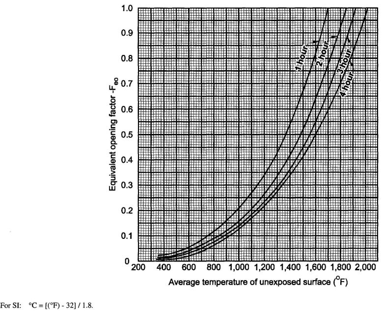
FIGURE 705.7 EQUIVALENT OPENING FACTOR
174| FIRE SEPARATION DISTANCE (feet) | DEGREE OF OPENING PROTECTION | ALLOWABLE AREAa |
|---|---|---|
| 0 to less than 3b,c | Unprotected, Nonsprinklered (UP, NS) | Not Permitted |
| Unprotected, Sprinklered (UP, S)i | Not Permitted | |
| Protected (P) | Not Permitted | |
| 3 to less than 5d,e | Unprotected, Nonsprinklered (UP, NS) | Not Permitted |
| Unprotected, Sprinklered (UP,S)i | 15% | |
| Protected (P) | 15% | |
| 5 to less than 10e,f | Unprotected, Nonsprinklered (UP, NS) | 10%h |
| Unprotected, Sprinklered (UP, S)i | 25% | |
| Protected (P) | 25% | |
| 10 to less than 15e,f,g | Unprotected, Nonsprinklered (UP, NS) | 15%h |
| Unprotected, Sprinklered (UP,S)i | 45% | |
| Protected (P) | 45% | |
| 15 to less than 20f,g | Unprotected, Nonsprinklered (UP, NS) | 25% |
| Unprotected, Sprinklered (UP,S)i | 75% | |
| Protected (P) | 75% | |
| 20 to less than 25f,g | Unprotected, Nonsprinklered (UP, NS) | 45% |
| Unprotected, Sprinklered (UP, S)i | No Limit | |
| Protected (P) | No Limit | |
| 25 to less than 30f,g | Unprotected, Nonsprinklered (UP, NS) | 70% |
| Unprotected, Sprinklered (UP,S)i | No Limit | |
| Protected (P) | No Limit | |
| 30 or greater | Unprotected, Nonsprinklered (UP, NS) | No Limit |
| Unprotected, Sprinklered (UP,S)i | Not Required | |
| Protected (P) | Not Required | |
| For SI: 1 foot = 304.8 mm. | ||
| UP, NS = Unprotected openings in buildings not equipped throughout with an automatic sprinkler system in accordance with Section 903.3.1.1. | ||
| UP, S = Unprotected openings in buildings equipped throughout with an automatic sprinkler system in accordance with Section 903.3.1.1. | ||
| P = Openings protected with an opening protective assembly in accordance with Section 705.8.2. | ||
| a. Values indicated are the percentage of the area of the exterior wall, per story. | ||
| b. For the requirements for fire walls of buildings with differing heights, see Section 706.6.1. | ||
| c. For openings in a fire wall for buildings on the same lot, see Section 706.8. | ||
| d. The maximum percentage of unprotected and protected openings shall be 25 percent for Group R-3 occupancies. | ||
| e. Unprotected openings shall not be permitted for openings with a fire separation distance of less than 15 feet for Group H-2 and H-3 occupancies. | ||
| f. The area of unprotected and protected openings shall not be limited for Group R-3 occupancies, with a fire separation distance of 5 feet or greater. | ||
| g. The area of openings in an open parking structure with a fire separation distance of 10 feet or greater shall not be limited. | ||
| h. Includes buildings accessory to Group R-3. | ||
| i. Not applicable to Group H-1, H-2 and H-3 occupancies. | ||
705.8.2 Protected openings. Where openings are required to be protected, fire doors and fire shutters shall comply with Section 715.4 and fire window assemblies shall comply with Section 715.5.
Exception: Opening protectives are not required where the building is equipped throughout with an automatic sprinkler system in accordance with Section 903.3.1.1 and the exterior openings are protected by a water curtain using automatic sprinklers approved for that use.
705.8.3 Unprotected openings. Where unprotected openings are permitted, windows and doors shall be constructed of any approved materials. Glazing shall conform to the requirements of Chapters 24 and 26.
705.8.4 Mixed openings. Where both unprotected and protected openings are located in the exterior wall in any story of a building, the total area of openings shall be determined in accordance with the following:

where:
Ap = Actual area of protected openings, or the equivalent area of protected openings, Ae (see Section 705.7.).
ap = Allowable area of protected openings.
Au = Actual area of unprotected openings.
au = Allowable area of unprotected openings.
705.8.5 Vertical separation of openings. Openings in exterior walls in adjacent stories shall be separated vertically to protect against fire spread on the exterior of the buildings where the openings are within 5 feet (1524 mm) of each other horizontally and the opening in the lower story is not a protected opening with a fire protection rating of not less than ¾ hour. Such openings shall be separated vertically at least 3 feet (914 mm) by spandrel girders, exterior walls or other similar assemblies that have a fire-resistance rating of at least 1 hour or by flame barriers that extend horizontally at least 30 inches (762 mm) beyond the exterior wall. Flame barriers shall also have a fire-resistance rating of at least 1 hour. The unexposed surface temperature limitations specified in ASTM E 119 or UL 263 shall not apply to the flame barriers or vertical separation unless otherwise required by the provisions of this code.
Exceptions:
705.8.6 Vertical exposure. For buildings on the same lot, opening protectives having a fire protection rating of not less than ¾ hour shall be provided in every opening that is less than 15 feet (4572 mm) vertically above the roof of an adjacent building or structure based on assuming an imaginary line between them. The opening protectives are required where the fire separation distance between the imaginary line and the adjacent building or structure is less than 15 feet (4572 mm).
Exceptions:
705.9 Joints. Joints made in or between exterior walls required by this section to have a fire-resistance rating shall comply with Section 714.
Exception: Joints in exterior walls that are permitted to have unprotected openings.
705.9.1 Voids. The void created at the intersection of a floor/ceiling assembly and an exterior curtain wall assembly shall be protected in accordance with Section 714.4.
705.10 Ducts and air transfer openings. Penetrations by air ducts and air transfer openings in fire-resistance-rated exterior walls required to have protected openings shall comply with Section 716.
Exception: Foundation vents installed in accordance with this code are permitted.
705.11 Parapets. Parapets shall be provided on exterior walls of buildings.
Exceptions: A parapet need not be provided on an exterior wall where any of the following conditions exist:
705.11.1 Parapet construction. Parapets shall have the same fire-resistance rating as that required for the supporting wall, and on any side adjacent to a roof surface, shall have noncombustible faces for the uppermost 18 inches (457 mm), including counterflashing and coping materials. The height of the parapet shall not be less than 30 inches (762 mm) above the point where the roof surface and the wall intersect. Where the roof slopes toward a parapet at a slope greater than two units vertical in 12 units horizontal (16.7-percent slope), the parapet shall extend to the same height as any portion of the roof within a fire separation distance where protection of wall openings is required, but in no case shall the height be less than 30 inches (762 mm).
706.1 General. Each portion of a building separated by one or more fire walls that comply with the provisions of this section shall be considered a separate building. The extent and location of such fire walls shall provide a complete separation. Where a fire wall also separates occupancies that are required to be separated by a fire barrier wall, the most restrictive requirements of each separation shall apply.
706.1.1 Party walls. Any wall located on a lot line between adjacent buildings, which is used or adapted for joint service between the two buildings, shall be constructed as a fire wall in accordance with Section 706. Party walls shall be constructed without openings and shall create separate buildings.
Exception: Openings in a party wall separating an anchor building and a mall shall be in accordance with Section 402.7.3.1.
706.2 Structural stability. Fire walls shall have sufficient structural stability under fire conditions to allow collapse of construction on either side without collapse of the wall for the duration of time indicated by the required fire-resistance rating.
706.3 Materials. Fire walls shall be of any approved noncombustible materials.
Exception: Buildings of Type V construction.
706.4 Fire-resistance rating. Fire walls shall have a fire-resistance rating of not less than that required by Table 706.4.
| GROUP | FIRE-RESISTANCE RATING (hours) |
|---|---|
| A, B, E, H-4, I, R-1, R-2, R-2.1, U, L | 3a |
| F-1, H-3b, H-5, M, S-1 | 3 |
| H-1, H-2 | 4b |
| F-2, S-2, R-3, R-4 | 2 |
| a. In Type II or V construction, walls shall be permitted to have a 2-hour fire-resistance rating. | |
| b. For Group H-1, H-2 or H-3 buildings, also see Sections 415.4 and 415.5. | |
706.5 Horizontal continuity. Fire walls shall be continuous from exterior wall to exterior wall and shall extend at least 18 inches (457 mm) beyond the exterior surface of exterior walls.
Exceptions:
706.5.1 Exterior walls. Where the fire wall intersects exterior walls, the fire-resistance rating and opening protection of the exterior walls shall comply with one of the following:
706.5.2 Horizontal projecting elements. Fire walls shall extend to the outer edge of horizontal projecting elements such as balconies, roof overhangs, canopies, marquees and similar projections that are within 4 feet (1220 mm) of the fire wall.
Exceptions:
706.6 Vertical continuity. Fire walls shall extend from the foundation to a termination point as least 30 inches (762 mm) above both adjacent roofs.
Exceptions:
 -inch (15.9 mm) Type X gypsum board directly beneath the underside of the roof sheathing or deck, supported by a minimum of 2-inch (15 mm) nominal ledgers attached to the sides of the roof framing members for a minimum distance of 4 feet (1220 mm) on both sides of the fire wall.
706.6.1 Stepped buildings. Where a fire wall serves as an exterior wall for a building and separates buildings having different roof levels, such wall shall terminate at a point not less than 30 inches (762 mm) above the lower roof level, provided the exterior wall for a height of 15 feet (4572 mm) above the lower roof is not less than 1-hour fire-resistance-rated construction from both sides with openings protected by fire assemblies having a fire protection rating of not less than ¾ hour.
Exception: Where the fire wall terminates at the underside of the roof sheathing, deck or slab of the lower roof, provided:
706.7 Combustible framing in fire walls. Adjacent combustible members entering into a concrete or masonry fire wall from opposite sides shall not have less than a 4-inch (102 mm) distance between embedded ends. Where combustible members frame into hollow walls or walls of hollow units, hollow spaces shall be solidly filled for the full thickness of the wall and for a distance not less than 4 inches (102 mm) above, below and between the structural members, with noncombustible materials approved for fireblocking.
706.8 Openings. Each opening through a fire wall shall be protected in accordance with Section 715.4 and shall not exceed 156 square feet (15 m2). The aggregate width of openings at any floor level shall not exceed 25 percent of the length of the wall.
Exceptions:
706.9 Penetrations. Penetrations of fire walls shall comply with Section 713.
706.10 Joints. Joints made in or between fire walls shall comply with Section 714.
706.11 Ducts and air transfer openings. Ducts and air transfer openings shall not penetrate fire walls.
Exception: Penetrations by ducts and air transfer openings of fire walls that are not on a lot line shall be allowed provided the penetrations comply with Section 716. The size and aggregate width of all openings shall not exceed the limitations of Section 706.8.
707.1 General. Fire barriers installed as required elsewhere in this code or the International Fire Code shall comply with this section.
707.2 Materials. Fire barriers shall be of materials permitted by the building type of construction.
707.3 Fire-resistance rating. The fire-resistance rating of fire barriers shall comply with this section.
707.3.1 Shaft enclosures. The fire-resistance rating of the fire barrier separating building areas from a shaft shall comply with Section 708.4.
707.3.2 Exit enclosures. The fire-resistance rating of the fire barrier separating building areas from an exit shall comply with Section 1022.1.
707.3.3 Exit passageway. The fire-resistance rating of the fire barrier separating building areas from an exit passageway shall comply with Section 1023.3.
707.3.4 Horizontal exit. The fire-resistance rating of the separation between building areas connected by a horizontal exit shall comply with Section 1025.1.
707.3.5 Atriums. The fire-resistance rating of the fire barrier separating atriums shall comply with Section 404.6.
707.3.6 Incidental accessory occupancies. The fire barrier separating incidental accessory occupancies from other spaces in the building shall have a fire-resistance rating of not less than that indicated in Table 508.2.5.
707.3.7 Control areas. Fire barriers separating control areas shall have a fire-resistance rating of not less than that required in Section 414.2.4.
707.3.8 Separated occupancies. Where the provisions of Section 508.4 are applicable, the fire barrier separating mixed occupancies shall have a fire-resistance rating of not less than indicated in Table 508.4 based on the occupancies being separated.
707.3.9 Fire areas. The fire barriers or horizontal assemblies, or both, separating a single occupancy into different fire areas shall have a fire-resistance rating of not less than that indicated in Table 707.3.9. The fire barriers or horizontal assemblies, or both, separating fire areas of mixed occupancies shall have a fire-resistance rating of not less than the highest value indicated in Table 707.3.9 for the occupancies under consideration.
| OCCUPANCY GROUP | FIRE-RESISTANCE RATING (hours) |
|---|---|
| H-1, H-2 | 4 |
| F-1, H-3, S-1 | 3 |
| A, B, E, F-2, H-4, H-5, I, L, M, R, S-2 | 2 |
| U | 1 |
707.4 Exterior walls. Where exterior walls serve as a part of a required fire-resistance-rated shaft or exit enclosure, or separation, such walls shall comply with the requirements of Section 705 for exterior walls and the fire-resistance-rated enclosure or separation requirements shall not apply.
Exception: Exterior walls required to be fire-resistance rated in accordance with Section 1019 for exterior egress balconies, Section 1022.6 for exit enclosures and Section 1026.6 for exterior exit ramps and stairways.
707.5 Continuity. Fire barriers shall extend from the top of the floor/ceiling assembly below to the underside of the floor or roof sheathing, slab or deck above and shall be securely attached thereto. Such fire barriers shall be continuous through concealed spaces, such as the space above a suspended ceiling.
707.5.1 Supporting construction. The supporting construction for a fire barrier shall be protected to afford the required fire-resistance rating of the fire barrier supported. Hollow vertical spaces within a fire barrier shall be fireblocked in accordance with Section 717.2 at every floor level.
Exceptions:
707.6 Openings. Openings in a fire barrier shall be protected in accordance with Section 715. Openings shall be limited to a maximum aggregate width of 25 percent of the length of the wall, and the maximum area of any single opening shall not exceed 156 square feet (15 m2). Openings in exit enclosures and exit passageways shall also comply with Sections 1022.3 and 1023.5, respectively.
Exceptions:
707.7 Penetrations. Penetrations of fire barriers shall comply with Section 713.
707.7.1 Prohibited penetrations. Penetrations into an exit enclosure or an exit passageway shall be allowed only when permitted by Section 1022.4 or 1023.6, respectively.
707.8 Joints. Joints made in or between fire barriers, and joints made at the intersection of fire barriers with underside of the floor or roof sheathing, slab or deck above, shall comply with Section 714.
707.9 Ducts and air transfer openings. Penetrations in a fire barrier by ducts and air transfer openings shall comply with Section 716.
708.1 General. The provisions of this section shall apply to shafts required to protect openings and penetrations through floor/ceiling and roof/ceiling assemblies. Shaft enclosures shall be constructed as fire barriers in accordance with Section 707 or horizontal assemblies in accordance with Section 712, or both.
708.2 Shaft enclosure required. Openings through a floor/ceiling assembly shall be protected by a shaft enclosure complying with this section.
Exceptions:
708.3 Materials. The shaft enclosure shall be of materials permitted by the building type of construction.
708.4 Fire-resistance rating. Shaft enclosures shall have a fire-resistance rating of not less than 2 hours where connecting four stories or more, and not less than 1 hour where connecting less than four stories. The number of stories connected by the shaft enclosure shall include any basements but not any mezzanines. Shaft enclosures shall have a fire-resistance rating not less than the floor assembly penetrated, but need not exceed 2 hours. Shaft enclosures shall meet the requirements of Section 703.2.1.
708.5 Continuity. Shaft enclosures shall be constructed as fire barriers in accordance with Section 707 or horizontal assemblies constructed in accordance with Section 712, or both, and shall have continuity in accordance with Section 707.5 for fire barriers or Section 712.4 for horizontal assemblies as applicable.
708.6 Exterior walls. Where exterior walls serve as a part of a required shaft enclosure, such walls shall comply with the requirements of Section 705 for exterior walls and the fire-resistance-rated enclosure requirements shall not apply.
Exception: Exterior walls required to be fire-resistance rated in accordance with Section 1019.2 for exterior egress balconies, Section 1022.6 for exit enclosures and Section 1026.6 for exterior exit ramps and stairways.
708.7 Openings. Openings in a shaft enclosure shall be protected in accordance with Section 715 as required for fire barriers. Doors shall be self- or automatic-closing by smoke detection in accordance with Section 715.4.8.3.
708.7.1 Prohibited openings. Openings other than those necessary for the purpose of the shaft shall not be permitted in shaft enclosures.
708.8 Penetrations. Penetrations in a shaft enclosure shall be protected in accordance with Section 713 as required for fire barriers.
181708.8.1 Prohibited penetrations. Penetrations other than those necessary for the purpose of the shaft shall not be permitted in shaft enclosures.
708.9 Joints. Joints in a shaft enclosure shall comply with Section 714.
708.10 Ducts and air transfer openings. Penetrations of a shaft enclosure by ducts and air transfer openings shall comply with Section 716.
708.11 Enclosure at the bottom. Shafts that do not extend to the bottom of the building or structure shall comply with one of the following:
Exceptions:
708.12 Enclosure at the top. A shaft enclosure that does not extend to the underside of the roof sheathing, deck or slab of the building shall be enclosed at the top with construction of the same fire-resistance rating as the topmost floor penetrated by the shaft, but not less than the fire-resistance rating required for the shaft enclosure.
708.13 Refuse and laundry chutes. Refuse and laundry chutes, access and termination rooms and incinerator rooms shall meet the requirements of Sections 708.13.1 through 708.13.6.
Exception: Chutes serving and contained within a single dwelling unit.
708.13.1 Refuse and laundry chute enclosures. A shaft enclosure containing a refuse or laundry chute shall not be used for any other purpose and shall be enclosed in accordance with Section 708.4. Openings into the shaft, including those from access rooms and termination rooms, shall be protected in accordance with this section and Section 715. Openings into chutes shall not be located in corridors. Doors shall be self-or automatic-closing upon the actuation of a smoke detector in accordance with Section 715.4.8.3, except that heat-activated closing devices shall be permitted between the shaft and the termination room.
708.13.2 Materials. A shaft enclosure containing a refuse or laundry chute shall be constructed of materials as permitted by the building type of construction.
708.13.3 Refuse and laundry chute access rooms. Access openings for refuse and laundry chutes shall be located in rooms or compartments enclosed by not less than 1-hour fire barriers constructed in accordance with Section 707 or horizontal assemblies constructed in accordance with Section 712, or both. Openings into the access rooms shall be protected by opening protectives having a fire protection rating of not less than ¾ hour. Doors shall be self- or automatic-closing upon the detection of smoke in accordance with Section 715.4.8.3.
708.13.4 Termination room. Refuse and laundry chutes shall discharge in to an enclosed room separated from the remainder of the building by not less than 1-hour fire barriers constructed in accordance with Section 707 or horizontal assemblies constructed in accordance with Section 712, or both. Openings into the termination room shall be protected by opening protectives having a fire protection rating of not less than ¾ hour. Doors shall be self- or automatic-closing upon the detection of smoke in accordance with Section 715.4.8.3. Refuse chutes shall not terminate in an incinerator room. Refuse and laundry rooms that are not provided with chutes need only comply with Table 508.2.5.
708.13.5 Incinerator room. Incinerator rooms shall comply with Table 508.2.5.
708.13.6 Automatic sprinkler system. An approved automatic sprinkler system shall be installed in accordance with Section 903.2.11.2.
708.14 Elevator, dumbwaiter and other hoistways. Elevator, dumbwaiter and other hoistway enclosures shall be constructed in accordance with Section 708 and Chapter 30.
708.14.1 Elevator lobby. An enclosed elevator lobby shall be provided at each floor where an elevator shaft enclosure connects more than two stories in Group A, E, H, I, L, R-1, R-2 and R-2.1occupancies, high-rise buildings, and other applications listed in Section 1.11 regulated by the Office of the State Fire Marshal, and more than three stories for all other occupancies. The lobby enclosure shall separate the elevator shaft enclosure doors from each floor by fire partitions. In addition to the requirements in Section 709 for fire partitions, doors protecting openings in the elevator lobby enclosure walls shall also comply with Section 715.4.3 as required for corridor walls and penetrations of the elevator lobby enclosure by ducts and air transfer openings shall be
182protected as required for corridors in accordance with Section 716.5.4.1. Elevator lobbies shall have at least one means of egress complying with Chapter 10 and other provisions within this code.
Exceptions:
See Section 403.6 for additional requirements for highrise buildings.
708.14.1.1 Areas of refuge. Areas of refuge shall be provided as required in Section 1007.
708.14.2 Enclosed elevator lobby. Where elevator hoistway pressurization is provided in lieu of required enclosed elevator lobbies, the pressurization system shall comply with this section.
708.14.2.1 Pressurization requirements. Elevator hoistways shall be pressurized to maintain a minimum positive pressure of 0.10 inches of water (25 Pa) and a maximum positive pressure of 0.25 inches of water (67 Pa) with respect to adjacent occupied space on all floors. This pressure shall be measured at the midpoint of each hoistway door, with all elevator cars at the floor of recall and all hoistway doors on the floor of recall open and all other hoistway doors closed. The opening and closing of hoistway doors at each level must be demonstrated during this test. The supply air intake shall be from an outside, uncontaminated source located a minimum distance of 20 feet (6096 mm) from any air exhaust system or outlet.
708.14.2.2 Rational analysis. A rational analysis complying with Section 909.4 shall be submitted with the construction documents.
708.14.2.3 Ducts for system. Any duct system that is part of the pressurization system shall be protected with the same fire-resistance rating as required for the elevator shaft enclosure.
708.14.2.4 Fan system. The fan system provided for the pressurization system shall be as required by this section.
708.14.2.4.1 Fire resistance. When located within the building, the fan system that provides the pressurization shall be protected with the same fire-resistance rating required for the elevator shaft enclosure.
708.14.2.4.2 Smoke detection. The fan system shall be equipped with a smoke detector that will automatically shut down the fan system when smoke is detected within the system.
708.14.2.4.3 Separate systems. A separate fan system shall be used for each elevator hoistway.
708.14.2.4.4 Fan capacity. The supply fan shall either be adjustable with a capacity of at least 1,000 cfm (.4719 m3/s) per door, or that specified by a registered design professional to meet the requirements of a designed pressurization system.
708.14.2.5 Standby power. The pressurization system shall be provided with standby power from the same source as other required emergency systems for the building.
183708.14.2.6 Activation of pressurization system. The elevator pressurization system shall be activated upon activation of the building fire alarm system or upon activation of the elevator lobby smoke detectors. Where both a building fire alarm system and elevator lobby smoke detectors are present, each shall be independently capable of activating the pressurization system.
708.14.2.7 Special inspection. Special inspection for performance shall be required in accordance with Section 909.18.8. System acceptance shall be in accordance with Section 909.19.
708.14.2.8 Marking and identification. Detection and control systems shall be marked in accordance with Section 909.14.
708.14.2.9 Control diagrams. Control diagrams shall be provided in accordance with Section 909.15.
708.14.2.10 Control panel. A control panel complying with Section 909.16 shall be provided.
708.14.2.11 System response time. Hoistway pressurization systems shall comply with the requirements for smoke control system response time in Section 909.17.
709.1 General. The following wall assemblies shall comply with this section.
709.2 Materials. The walls shall be of materials permitted by the building type of construction.
709.3 Fire-resistance rating. Fire partitions shall have a fire-resistance rating of not less than 1 hour.
Exceptions:
709.4 Continuity. Fire partitions shall extend from the top of the foundation or floor/ceiling assembly below to the underside of the floor or roof sheathing, slab or deck above or to the fire-resistance-rated floor/ceiling or roof/ceiling assembly above, and shall be securely attached thereto. If the partitions are not continuous to the sheathing, deck or slab, and where constructed of combustible construction, the space between the ceiling and the sheathing, deck or slab above shall be fireblocked or draftstopped in accordance with Sections 717.2 and 717.3 at the partition line. The supporting construction shall be protected to afford the required fire-resistance rating of the wall supported, except for walls separating tenant spaces in covered mall buildings, walls separating dwelling units, walls separating sleeping units and corridor walls in buildings of Type IIB, IIIB and VB construction.
Exceptions:
709.5 Exterior walls. Where exterior walls serve as a part of a required fire-resistance-rated separation, such walls shall comply with the requirements of Section 705 for exterior walls, and the fire-resistance-rated separation requirements shall not apply.
184Exception: Exterior walls required to be fire-resistance rated in accordance with Section 1019.2 for exterior egress balconies, Section 1022.6 for exit enclosures and Section 1026.6 for exterior exit ramps and stairways.
709.6 Openings. Openings in a fire partition shall be protected in accordance with Section 715.
709.7 Penetrations. Penetrations of fire partitions shall comply with Section 713.
709.8 Joints. Joints made in or between fire partitions shall comply with Section 714.
709.9 Ducts and air transfer openings. Penetrations in a fire partition by ducts and air transfer openings shall comply with Section 716.
710.1 General. Smoke barriers shall comply with this section.
710.2 Materials. Smoke barriers shall be of materials permitted by the building type of construction.
710.3 Fire-resistance rating. A 1-hour fire-resistance rating is required for smoke barriers.
Exception: Smoke barriers constructed of minimum 0.10-inch-thick (2.5 mm) steel in Group I-3 buildings.
710.4 Continuity. Smoke barriers shall form an effective membrane continuous from outside wall to outside wall and from the top of the foundation or floor/ceiling assembly below to the underside of the floor or roof sheathing, deck or slab above, including continuity through concealed spaces, such as those found above suspended ceilings, and interstitial structural and mechanical spaces. The supporting construction shall be protected to afford the required fire-resistance rating of the wall or floor supported in buildings of other than Type IIB, IIIB or VB construction.
Exception: Smoke-barrier walls are not required in interstitial spaces where such spaces are designed and constructed with ceilings that provide resistance to the passage of fire and smoke equivalent to that provided by the smoke-barrier walls.
710.5 Openings. Openings in a smoke barrier shall be protected in accordance with Section 715.
Exceptions:
710.6 Penetrations. Penetrations of smoke barriers shall comply with Section 713.
710.7 Joints. Joints made in or between smoke barriers shall comply with Section 714.
710.8 Ducts and air transfer openings. Penetrations in a smoke barrier by ducts and air transfer openings shall comply with Section 716.
711.1 General. Smoke partitions installed as required elsewhere in the code shall comply with this section.
711.2 Materials. The walls shall be of materials permitted by the building type of construction. In Group 1-2 and 1-2.1, smoke partitions shall have framing covered with noncombustible materials having an approved thermal barrier with an index of not less than 15 in accordance with FM 4880, UL 1040, NFPA 286 or UL 1715.
711.3 Fire-resistance rating. Unless required elsewhere in the code, smoke partitions are not required to have a fire-resistance rating.
711.4 Continuity. Smoke partitions shall extend from the top of the foundation or floor below to the underside of the floor or roof sheathing, deck or slab above or to the underside of the ceiling above where the ceiling membrane is constructed to limit the transfer of smoke.
711.5 Openings. Windows shall be sealed to resist the free passage of smoke or be automatic-closing upon detection of smoke. Doors in smoke partitions shall comply with this section.
711.5.1 Louvers. Doors in smoke partitions shall not include louvers.
711.5.2 Smoke and draft control doors. Where required elsewhere in the code, doors in smoke partitions shall meet the requirements for a smoke and draft control door assembly tested in accordance with UL 1784. The air leakage rate of the door assembly shall not exceed 3.0 cubic feet per minute per square foot (0.015424 m3/(s · m2)) of door opening at 0.10 inch (24.9 Pa) of water for both the ambient temperature test and the elevated temperature exposure test. Installation of smoke doors shall be in accordance with NFPA 105.
711.5.3 Self-or automatic-closing doors. Where required elsewhere in the code, doors in smoke partitions shall be self-or automatic-closing by smoke detection in accordance with Section 715.4.8.3.
711.6 Penetrations and joints. The space around penetrating items and in joints shall be filled with an approved material to limit the free passage of smoke.
711.7 Ducts and air transfer openings. The space around a duct penetrating a smoke partition shall be filled with an approved material to limit the free passage of smoke. Air transfer openings in smoke partitions shall be provided with a smoke damper complying with Section 716.3.2.2. For Group A, E, H,I, L and R occupancies, high-rise buildings, and other applications listed in Section 1.11 regulated by the Office of the State
185Fire Marshal, duct openings in smoke partitions shall also be provided with a smoke damper complying with Section716.3.2.2.
Exceptions:
712.1 General. Floor and roof assemblies required to have a fire-resistance rating shall comply with this section. Nonfire-resistance-rated floor and roof assemblies shall comply with Section 713.4.2.
712.2 Materials. The floor and roof assemblies shall be of materials permitted by the building type of construction.
712.3 Fire-resistance rating. The fire-resistance rating of floor and roof assemblies shall not be less than that required by the building type of construction. Where the floor assembly separates mixed occupancies, the assembly shall have a fire-resistance rating of not less than that required by Section 508.4 based on the occupancies being separated. Where the floor assembly separates a single occupancy into different fire areas, the assembly shall have a fire-resistance rating of not less than that required by Section 707.3.9. Horizontal assemblies separating dwelling units in the same building and horizontal assemblies separating sleeping units in the same building shall be a minimum of 1-hour fire-resistance-rated construction.
Exception: Dwelling unit and sleeping unit separations in buildings of Type IIB, IIIB and VB construction shall have fire-resistance ratings of not less than ½ hour in buildings equipped throughout with an automatic sprinkler system in accordance with Section 903.3.1.1.
712.3.1 Ceiling panels. Where the weight of lay-in ceiling panels, used as part of fire-resistance-rated floor/ceiling or roof/ceiling assemblies, is not adequate to resist an upward force of 1 pound per square foot (48 Pa), wire or other approved devices shall be installed above the panels to prevent vertical displacement under such upward force.
712.3.2 Access doors. Access doors shall be permitted in ceilings of fire-resistance-rated floor/ceiling and roof/ceiling assemblies provided such doors are tested in accordance with ASTME 119 or UL 263 as horizontal assemblies and labeled by an approved agency for such purpose.
712.3.3 Unusable space. In 1-hour fire-resistance-rated floor assemblies, the ceiling membrane is not required to be installed over unusable crawl spaces. In 1-hour fire-resistance-rated roof assemblies, the floor membrane is not required to be installed where unusable attic space occurs above.
712.4 Continuity. Assemblies shall be continuous without openings, penetrations or joints except as permitted by this section and Sections 708.2, 713.4, 714 and 1022.1. Skylights and other penetrations through a fire-resistance-rated roof deck or slab are permitted to be unprotected, provided that the structural integrity of the fire-resistance-rated roof assembly is maintained. Unprotected skylights shall not be permitted in roof assemblies required to be fire-resistance-rated in accordance with Section 704.10. The supporting construction shall be protected to afford the required fire-resistance rating of the horizontal assembly supported.
Exception: In buildings of Type IIB, IIIB or VB construction, the construction supporting the horizontal assembly is not required to be fire-resistance-rated at the following:
712.5 Penetrations. Penetrations of horizontal assemblies shall comply with Section 713.
712.6 Joints. Joints made in or between horizontal assemblies shall comply with Section 714. The void created at the intersection of a floor/ceiling assembly and an exterior curtain wall assembly shall be protected in accordance with Section 714.4.
712.7 Ducts and air transfer openings. Penetrations in horizontal assemblies by ducts and air transfer openings shall comply with Section 716.
712.8 Floor fire door assemblies. Floor fire door assemblies used to protect openings in fire-resistance-rated floors shall be tested in accordance with NFPA 288, and shall achieve a fire-resistance rating not less than the assembly being penetrated. Floor fire door assemblies shall be labeled by an approved agency. The label shall be permanently affixed and shall specify the manufacturer, the test standard and the fire-resistance rating.
712.9 Smoke barrier. Where horizontal assemblies are required to resist the movement of smoke by other sections of this code in accordance with the definition of smoke barrier, penetrations and joints in such horizontal assemblies shall be protected as required for smoke barriers in accordance with Sections 713.5 and 714.6. Regardless of the number of stories connected by elevator shaft enclosures, doors located in elevator shaft enclosures that penetrate the horizontal assembly shall be protected by enclosed elevator lobbies complying with Section 708.14.1. Openings through horizontal assemblies shall be protected by shaft enclosures complying with Section 708. Horizontal assemblies shall not be allowed to have unprotected vertical openings.
186713.1 Scope. The provisions of this section shall govern the materials and methods of construction used to protect through penetrations and membrane penetrations of horizontal assemblies and fire-resistance-rated wall assemblies.
713.1.1 Ducts and air transfer openings. Penetrations of fire-resistance-rated walls by ducts that are not protected with dampers shall comply with Sections 713.2 through 713.3.3. Penetrations of horizontal assemblies not protected with a shaft as permitted by Exception 4 of Section 708.2, and not required to be protected with fire dampers by other sections of this code, shall comply with Sections 713.4 through 713.4.2.2. Ducts and air transfer openings that are protected with dampers shall comply with Section 716.
713.2 Installation details. Where sleeves are used, they shall be securely fastened to the assembly penetrated. The space between the item contained in the sleeve and the sleeve itself and any space between the sleeve and the assembly penetrated shall be protected in accordance with this section. Insulation and coverings on or in the penetrating item shall not penetrate the assembly unless the specific material used has been tested as part of the assembly in accordance with this section.
713.3 Fire-resistance-rated walls. Penetrations into or through fire walls, fire barriers, smoke barrier walls and fire partitions shall comply with Sections 713.3.1 through 713.3.3. Penetrations in smoke barrier walls shall also comply with Section 713.5.
713.3.1 Through penetrations. Through penetrations of fire-resistance-rated walls shall comply with Section 713.3.1.1 or 713.3.1.2.
Exception: Where the penetrating items are steel, ferrous or copper pipes, tubes or conduits, the annular space between the penetrating item and the fire-resistance-rated wall is permitted to be protected as follows:
713.3.1.1 Fire-resistance-rated assemblies. Penetrations shall be installed as tested in an approved fire-resistance-rated assembly.
713.3.1.2 Through-penetration firestop system. Through penetrations shall be protected by an approved penetration firestop system installed as tested in accordance with ASTM E 814 or UL 1479, with a minimum positive pressure differential of 0.01 inch (2.49 Pa) of water and shall have an F rating of not less than the required fire-resistance rating of the wall penetrated.
713.3.2 Membrane penetrations. Membrane penetrations shall comply with Section 713.3.1. Where walls or partitions are required to have a fire-resistance rating, recessed fixtures shall be installed such that the required fire-resistance will not be reduced.
Exceptions:
713.3.3 Dissimilar materials. Noncombustible penetrating items shall not connect to combustible items beyond the point of firestopping unless it can be demonstrated that the fire-resistance integrity of the wall is maintained.
713.4 Horizontal assemblies. Penetrations of a floor, floor/ceiling assembly or the ceiling membrane of a roof/ceiling assembly not required to be enclosed in a shaft by Section 708.2 shall be protected in accordance with Sections 713.4.1 through 713.4.2.2.
713.4.1 Fire-resistance-rated assemblies. Penetrations of the fire-resistance-rated floor, floor/ceiling assembly or the ceiling membrance of a roof/ceiling assembly shall comply with Sections 713.4.1.1 through 713.4.1.4 Penetrations in horizontal smoke barriers shall also comply with 713.5.
713.4.1.1 Through penetrations. Through penetrations of fire-resistance-rated horizontal assemblies shall comply with Section 713.4.1.1.1 or 713.4.1.1.2.
Exceptions:
713.4.1.1.1 Installation. Through penetrations shall be installed as tested in the approved fire-resistance-rated assembly.
713.4.1.1.2 Through-penetration firestop system. Through penetrations shall be protected by an approved through-penetration firestop system installed and tested in accordance with ASTM E 814 or UL 1479, with a minimum positive pressure differential of 0.01 inch of water (2.49 Pa). The system shall have an Frating/T rating of not less than 1 hour but not less than the required rating of the floor penetrated.
Exception: Floor penetrations contained and located within the cavity of a wall above the floor or below the floor do not require a T rating.
713.4.1.2 Membrane penetrations. Penetrations of membrances that are part of a horizontal assembly shall comply with Section 713.4.1.1.1 or 713.4.1.1.2. Where floor/ceiling assemblies are required to have a fire-resistance rating, recessed fixtures shall be installed such that the required fire resistance will not be reduced.
Exceptions:
- Membrane penetrations by steel, ferrous or copper conduits, pipes, tubes or vents, or concrete or masonry items where the annular space is protected either in accordance with Section 713.4.1.1 or to prevent the free passage of flame and the products of combustion. The aggregate area of the openings through the membrane shall not exceed 100 square inches (64 500 mm2) in any 100 square feet (9.3 m2) of ceiling area in assemblies tested without penetrations.
- Ceiling membrane penetrations of maximum 2-hour horizontal assemblies by steel electrical boxes that do not exceed 16 square inches (10 323 mm2) in area, provided the aggregate area of such penetrations does not exceed 100 square inches (44 500 mm2) in any 100 square feet (9.29 m2) of ceiling area, and the annular space between the ceiling membrane and the box does not exceed 1/8 inch(3.2 mm).
- Membrane penetrations by electrical boxes of any size or type, which have been listed as part 188 of an opening protective material system for use in horizontal assemblies and are installed in accordance with the instructions included in the listing.
- Membrane penetrations by listed electrical boxes of any material, provided such boxes have been tested for use in fire-resistance-rated assemblies and are installed in accordance with the instructions included in the listing. The annular space between the ceiling membrane and the box shall not exceed 1/8 inch (3.2 mm) unless listed otherwise.
- The annular space created by the penetration of a fire sprinkler, provided it is covered by a metal eschutcheon plate.
713.4.1.3 Ducts and air transfer openings. Penetrations of horizontal assemblies by ducts and air transfer openings shall comply with Section 716.
713.4.1.4 Dissimilar materials. Noncombustible penetrating items shall not connect to combustible materials beyond the point of firestopping unless it can be demonstrated that the fire-resistance integrity of the horizontal assembly is maintained.
713.4.2 Nonfire-resistance-rated assemblies. Penetrations of nonfire-resistance-rated floor or floor/ceiling assemblies or the ceiling membrance of a nonfire-resistance- rated roof/ceiling assembly shall meet the requirements of Section 708 or shall comply with Section 713.4.2.1 or 713.4.2.2.
713.4.2.1 Noncombustible penetrating items. Non-combustible penetrating items that connect not more than three stories are permitted, provided that the annular space is filled to resist the free passage of flame and the products of combustion with an approved noncombustible material or with a fill, void or cavity material that is tested and classified for use in through-penetration firestop systems.
713.4.2.2 Penetrating items. Penetrating items that connect not more than two stories are permitted, provided that the annular space is filled with an approved material to resist the free passage of flame and the products of combustion.
713.5 Penetrations in smoke barriers. Penetrations in smoke barriers shall be tested in accordance with the requirements of UL 1479 for air leakage. The air leakage rate of the penetration assemblies measured at 0.30 inch (7.47 Pa) of water in both the ambient temperature and elevated temperature tests, shall not exceed:
714.1 General. Joints installed in or between fire-resistance-rated walls, floor or floor/ceiling assemblies and roofs or roof/ceiling assemblies shall be protected by an approved fire-resistant joint system designed to resist the passage of fire for a time period not less than the required fire-resistance rating of the wall, floor or roof in or between which it is installed. Fire-resistant joint systems shall be tested in accordance with Section 714.3. The void created at the intersection of a floor/ceiling assembly and an exterior curtain wall assembly shall be protected in accordance with Section 714.4.
Exception: Fire-resistant joint systems shall not be required for joints in all of the following locations:
714.2 Installation. Fire-resistant joint systems shall be securely installed in or on the joint for its entire length so as not to dislodge, loosen or otherwise impair its ability to accommodate expected building movements and to resist the passage of fire and hot gases.
714.3 Fire test criteria. Fire-resistant joint systems shall be tested in accordance with the requirements of either ASTM E 1966 or UL 2079. Nonsymmetrical wall joint systems shall be tested with both faces exposed to the furnace, and the assigned fire-resistance rating shall be the shortest duration obtained from the two tests. When evidence is furnished to show that the wall was tested with the least fire-resistant side exposed to the furnace, subject to acceptance of the building official, the wall need not be subjected to tests from the opposite side.
Exception: For exterior walls with a horizontal fire separation distance greater than 5 feet (1524 mm), the joint system shall be required to be tested for interior fire exposure only.
714.4 Exterior curtain wall/floor intersection. Where fire resistance-rated floor or floor/ceiling assemblies are required, voids created at the intersection of the exterior curtain wall assemblies and such floor assemblies shall be sealed with an approved system to prevent the interior spread of fire. Such systems shall be securely installed and tested in accordance with ASTM E 2307 to prevent the passage of flame for the time period at least equal to the fire-resistance rating of the floor
189assembly and prevent the passage of heat and hot gases sufficient to ignite cotton waste. Height and fire-resistance requirements for curtain wall spandrels shall comply with Section 705.8.5.
714.4.1 Exterior curtain wall/nonfire-resistance-rated floor assembly intersections. Voids created at the intersection of exterior curtain wall assemblies and nonfire-resistance-rated floor or floor/ceiling assemblies shall be scaled with an approved material or system to retard the interior spread of fire and hot gases between stories.
714.5 Spandrel wall. Height and fire-resistance requirements for curtain wall spandrels shall comply with Section 705.8.5. Where Section 705.8.5 does not require a fire-resistance-rated spandrel wall, the requirements of Section 714.4 shall still apply to the intersection between the spandrel wall and the floor.
714.6 Fire-resistant joint systems in smoke barriers. Fire-resistant joint systems in smoke barriers, and joints at the intersection of a horizontal smoke barrier and an exterior curtain wall, shall be tested in accordance with the requirements of UL 2079 for air leakage. The air leakage rate of the joint shall not exceed 5 cfm per lineal foot (0.00775 m3/s · m) of joint at 0.30 inch (7.47 Pa) of water for both the ambient temperature and elevated temperature tests.
715.1 General. Opening protectives required by other sections of this code shall comply with the provisions of this section.
715.2 Fire-resistance-rated glazing. Fire-resistance-rated glazing tested as part of a fire-resistance-rated wall assembly in accordance with ASTM E 119 or UL 263 and labeled in accordance with Section 703.5 shall be permitted in fire doors and fire window assemblies in accordance with their listings and shall not otherwise be required to comply with this section.
715.3 Alternative methods for determining fire protection ratings. The application of any of the alternative methods listed in this section shall be based on the fire exposure and acceptance criteria specified in NFPA 252, NFPA 257 or UL 9. The required fire resistance of an opening protective shall be permitted to be established by any of the following methods or procedures:
715.4 Fire door and shutter assemblies. Approved fire door and fire shutter assemblies shall be constructed of any material or assembly of component materials that conforms to the test requirements of Section 715.4.1, 715.4.2 or 715.4.3 and the fire protection rating indicated in Table 715.4. Fire door frames with transom lights, sidelights or both shall be permitted in accordance with Section 715.4.5. Fire door assemblies and shutters shall be installed in accordance with the provisions of this section and NFPA 80.
Exceptions:
| TYPE OF ASSEMBLY | REQUIRED ASSEMBLY RATING (hours) | MINIMUM FIRE DOOR AND FIRE SHUTTER ASSEMBLY RATING (hours) |
|---|---|---|
| Fire walls and fire barriers having a required fire-resistance rating greater than 1 hour | 4 3 2 1½ | 3 3a 1½ 1½ |
| Fire barriers having a required fire-resistance rating of 1 hour: Shaft, exit enclosure and exit passageway walls Other fire barriers | 1 1 | 1 ¾ |
| Fire partitions: Corridor walls Other fire partitions | 1 0.5 1 0.5 | 1/3b 1/3b ¾ 1/3 |
| Exterior walls | 3 2 1 | 1½ 1½ ¾ |
| Smoke barriers | 1 | 1/3b |
| a. Two doors, each with a fire protection rating of 1½ hours, installed on opposite sides of the same opening in a fire wall, shall be deemed equivalent in fire protection rating to one 3-hour fire door. | ||
| b. For testing requirements, see Section 715.4.3. | ||
715.4.1 Side-hinged or pivoted swinging doors. Fire door assemblies with side-hinged and pivoted swinging doors shall be tested in accordance with NFPA 252 or UL 10C. After 5 minutes into the NFPA 252 test, the neutral pressure level in the furnace shall be established at 40 inches (1016 mm) or less above the sill.
715.4.2 Other types of assemblies. Fire door assemblies with other types of doors, including swinging elevator doors and fire shutter assemblies, shall be tested in accordance with NFPA 252 or UL 10B. The pressure in the furnace shall be maintained as nearly equal to the atmospheric pressure as possible. Once established, the pressure shall be maintained during the entire test period.
715.4.3 Door assemblies in corridors and smoke barriers. Fire door assemblies required to have a minimum fire protection rating of 20 minutes where located in corridor walls or smoke barrier walls having a fire-resistance rating in accordance with Table 715.4 shall be tested in accordance with NFPA 252 or UL 10C without the hose stream test.
Exceptions:
715.4.3.1 Smoke and draft control. Fire door assemblies shall also meet the requirements for a smoke and draft control door assembly tested in accordance with UL 1784. The air leakage rate of the door assembly shall not exceed 3.0 cubic feet per minute per square foot (0.01524 m3/s · m2) of door opening at 0.10 inch (24.9 Pa) of water for both the ambient temperature and elevated temperature tests. Louvers shall be prohibited. Installation of smoke doors shall be in accordance with NFPA 105.
715.4.3.2 Glazing in door assemblies. In a 20-minute fire door assembly, the glazing material in the door itself shall have a minimum fire-protection-rated glazing of 20 minutes and shall be exempt from the hose stream test. Glazing material in any other part of the door assembly, including transom lights and sidelights, shall be tested in accordance with NFPA 257 or UL 9, including the hose stream test, in accordance with Section 715.5.
715.4.4 Doors in exit enclosures and exit passageways. Fire door assemblies in exit enclosures and exit passageways shall have a maximum transmitted temperature end point of not more than 450°F (250°C) above ambient at the end of 30 minutes of standard fire test exposure.
Exception: The maximum transmitted temperature rise is not required in buildings equipped throughout with an automatic sprinkler system installed in accordance with Section 903.3.1.1.
715.4.4.1 Glazing in doors. Fire-protection-rated glazing in excess of 100 square inches (0.065 m2) shall be permitted in fire door assemblies when tested as components of the door assemblies and not as glass lights, and shall have a maximum transmitted temperature rise of 450°F (250°C) in accordance with Section 715.4.4.
Exception: The maximum transmitted temperature rise is not required in buildings equipped throughout with an automatic sprinkler system installed in accordance with Section 903.3.1.1.
715.4.5 Fire door frames with transom lights and sidelights. Door frames with transom lights, sidelights, or both, shall be permitted where a ¾-hour fire protection rating or less is required in accordance with Table 715.4. Where a fire protection rating exceeding ¾-hour is required in accordance with Table 715.4, fire door frames with transom lights, sidelights, or both, shall be permitted where installed with fire-resistance-rated glazing tested as an assembly in accordance with ASTM E119 or UL 263.
715.4.6 Labeled protective assemblies. Fire door assemblies shall be labeled by an approved agency. The labels shall comply with NFPA 80, and shall be permanently affixed to the door or frame.
715.4.6.1 Fire door labeling requirements. Fire doors shall be labeled showing the name of the manufacturer or other identification readily traceable back to the manufacturer, the name or trademark of the third-party inspection agency, the fire protection rating and, where required for fire doors in exit enclosured and exit passageways by Section 715.4.4, the maximum transmitted temperature end point. Smoke and draft control doors complying with UL 1784 shall be labeled as such and shall also comply with Section 715.4.6.3. Labels shall be approved and permanently affixed. The label shall be applied at the factory or location where fabrication and assembly are performed.
Exception: In Group I-3 doors which are required to be 45 minutes or higher shall be fire-rated assemblies or certified by the manufacturer as being equivalent to the required standard.
715.4.6.2 Oversized doors. Oversized fire doors shall bear an oversized fire door label by an approved agency or shall be provided with a certificate of inspection furnished by an approved testing agency. When a certificate of inspection is furnished by an approved testing agency, the certificate shall state that the door conforms to the
191requirements of design, materials and construction, but has not been subjected to the fire test.
715.4.6.3 Smoke and draft control door labeling requirements. Smoke and draft control doors complying with UL 1784 shall be labeled in accordance with Section 715.4.6.1 and shall show the letter "S" on the fire rating label of the door. This marking shall indicate that the door and frame assembly are in compliance when listed or labeled gasketing is also installed.
715.4.6.4 Fire door frame labeling requirements. Fire door frames shall be labeled showing the names of the manufacturer and the third-party inspection agency.
715.4.7 Glazing material. Fire-protection-rated glazing conforming to the opening protection requirements in Section 715.4 shall be permitted in fire door assemblies.
715.4.7.1 Size limitations. Fire-protection-rated glazing used in fire doors shall comply with the size limitations of NFPA 80.
Exceptions:
715.4.7.2 Exit and elevator protectives. Approved fire-protection-rated glazing used in fire door assemblies in elevator and exit enclosures shall be so located as to furnish clear vision of the passageway or approach to the elevator, ramp or stairway.
715.4.7.3 Labeling, Fire-protection-rated glazing shall bear a label or other identification showing the name of the manufacture, the test standard and information required in Section 715.5.9.1 that shall be issued by an approved agency and shall be permanently affixed to the glazing.
715.4.7.3.1 Identification. For fire protection-rated glazing, the label shall bear the following four-part identification: "D – H or NH – T or NT – XXX." "D" indicates that the glazing shall be used in fire door assemblies and that the glazing meets the fire protection requirements of NFPA 252. "H" shall indicate that the glazing meets the hose stream requirements of NFPA 252. "NH" shall indicate that the glazing does not meet the hose stream requirements of the test. "T" shall indicate that the glazing meets the temperature requirements of Section 715.4.4.1. "NT" shall indicate that the glazing does not meet the temperature requirements of Section 715.4.4.1. The placeholder "XXX" shall specify the fire-protection-rating period, in minutes.
715.4.7.4 Safety glazing. Fire-protection-rated glazing installed in fire doors in areas subject to human impact in hazardous locations shall comply with Chapter 24.
715.4.8 Door closing. Fire doors shall be self- or automatic-closing in accordance with this section.
Exceptions:
715.4.8.1 Latch required. Unless otherwise specifically permitted, single fire doors and both leaves of pairs of side-hinged swinging fire doors shall be provided with an active latch bolt that will secure the door when it is closed.
715.4.8.2 Automatic-closing fire door assemblies. Automatic-closing fire door assemblies shall be self-closing in accordance with NFPA 80.
715.4.8.3 Smoke-activated doors. Automatic-closing doors installed in the ollowin locations shall be automatic-closing by the actuation of smoke detectors installed in accordance with Section 907.3 or by loss of power to the smoke detector or hold-open device. Doors that are automatic-closing by smoke detection shall not have more than a 10-second delay before the door starts to close after the smoke detector is actuated:
In Group 1-2 occupancies smoke activated doors installed in the above locations shall be automatic closing by actuation of the fire alarm system, or actuation of smoke detectors installed in accordance with Section 907.10, or activation of the sprinkler system installed in accordance with Section 903.1.
715.4.8.4 Doors in pedestrian ways. Vertical sliding or vertical rolling steel fire doors in openings through which pedestrians travel shall be heat activated or activated by smoke detectors with alarm verification.
715.4.9 Swinging fire shutters. Where fire shutters of the swinging type are installed in exterior openings, not less than one row in every three vertical rows shall be arranged to be readily opened from the outside, and shall be identified by distinguishing marks or letters not less than 6 inches (152 mm) high.
715.4.10 Rolling fire shutters. Where fire shutters of the rolling type are installed, such shutters shall include approved automatic-closing devices.
715.5 Fire-protection-rated glazing. Glazing in fire window assemblies shall be fire-protection rated in accordance with this section and Table 715.5. Glazing in fire door assemblies shall comply with Section 715.4.7. Fire-protection-rated glazing shall be tested in accordance with and shall meet the acceptance criteria of NFPA 257 or UL 9. Fire-protection-rated glazing shall also comply with NFPA 80. Openings in nonfire-resistance-rated exterior wall assemblies that require protection in accordance with Section 705.3, 705.8, 705.8.5 or 705.8.6 shall have a fire-protection rating of not less than 3/4 hour.
Exceptions:
715.5.1 Testing under positive pressure. NFPA 257 or UL 9 shall evaluate fire-protection-rated glazing under positive pressure. Within the first 10 minutes of a test, the pressure in the furnace shall be adjusted so at least two-thirds of the test specimen is above the neutral pressure plane, and the neutral pressure plane shall be maintained at that height for the balance of the test.
| TYPE OF ASSEMBLY | REQUIRED ASSEMBLY RATING (hours) | MINIMUM FIRE WINDOW ASSEMBLY RATING (hours) | |
|---|---|---|---|
| Interior walls: | Fire walls | All | NPa |
| Fire barriers | >1 1 | NPa ¾ | |
| Smoke barriers | 1 | ¾ | |
| Fire partitions | 1 ½ | ¾ 1/3 | |
| Exterior walls | >1 1 | 1½ ¾ | |
| Party wall | All | NP | |
| NP = Not Permitted. | |||
| a. Not permitted except as specified in Section 715.2. | |||
715.5.2 Nonsymmetrical glazing systems. Nonsymmetrical fire-protection-rated glazing systems in fire partitions, fire barriers or in exterior walls with a fire separation distance of 5 feet (1524 mm) or less pursuant to Section 705 shall be tested with both faces exposed to the furnace, and the assigned fire protection rating shall be the shortest duration obtained from the two tests conducted in compliance with NFPA 257 or UL 9.
715.5.3 Safety glazing. Fire-protection-rated glazing installed in fire window assemblies in areas subject to human impact in hazardous locations shall comply with Chapter 24.
715.5.4 Wired glass. Steel window frame assemblies of 0.125-inch (3.2 mm) minimum solid section or of not less than nominal 0.048-inch-thick (1.2 mm) formed sheet steel members fabricated by pressing, mitering, riveting, interlocking or welding and having provision for glazing with 1/4-inch (6.4 mm) wired glass where securely installed in the building construction and glazed with 1/4-inch (6.4 mm)labeled wired glass shall be deemed to meet the requirements for a ¾-hour fire window assembly. Wired glass panels shall conform to the size limitations set forth in Table 715.5.4.
| OPENING FIRE PROTECTION RATING | MAXIMUM AREA (square Inches) | MAXIMUM HEIGHT (inches) | MAXIMUM WIDTH (inches) |
| 3 hours | 0 | 0 | 0 |
| 1½-hour doors in exterior walls | 0 | 0 | 0 |
| 1 and 1½ hours | 100 | 33 | 10 |
| 3/4 hour | 1,296 | 54 | 54 |
| 20 minutes | Not Limited | Not Limited | Not Limited |
| Fire window assemblies | 1,296 | 54 | 54 |
| For SI: 1 inch = 25.4 mm, 1 square inch = 645.2 mm2. | |||
715.5.5 Nonwired glass. Glazing other than wired glass in fire window assemblies shall be fire-protection-rated glazing installed in accordance with and complying with the size limitations set forth in NFPA 80.
715.5.6 Installation. Fire-protection-rated glazing shall be in the fixed position or be automatic-closing and shall be installed in approved frames.
715.5.7 Window mullions. Metal mullions that exceed a nominal height of 12 feet (3658 mm) shall be protected with materials to afford the same fire-resistance rating as required for the wall construction in which the protective is located.
715.5.8 Interior fire window assemblies. Fire-protection-rated glazing used in fire window assemblies located in fire partitions and fire barriers shall be limited to use in assemblies with a maximum fire-resistance rating of 1 hour in accordance with this section.
715.5.8.1 Where ¾-hour fire protection window assemblies permitted. Fire-protection-rated glazing requiring 45-minute opening protection in accordance with Table 715.5 shall be limited to fire partitions designed in accordance with Section 709 and fire barriers utilized in the applications set forth in Sections 707.3.6 and 707.3.8 where the fire-resistance rating does not exceed 1 hour.
715.5.8.2 Area limitations. The total area of windows shall not exceed 25 percent of the area of a common wall with any room.
715.5.9 Labeling requirements. Fire-protection-rated glazing shall bear a label or other identification showing the name of the manufacturer, the test standard and information required in Section 715.5.9.1 that shall be issued by an approved agency and shall be permanently affixed to the glazing.
715.5.9.1 Identification. For fire-protection-rated glazing, the label shall bear the following two-part identification: "OH – XXX." "OH" indicates that the glazing meets both the fire protection and the hose-stream requirements of NFPA 257 or UL 9 and is permitted to be used in openings. "XXX" represents the fire-protection rating period, in minutes, that was tested.
716.1 General. The provisions of this section shall govern the protection of duct penetrations and air transfer openings in assemblies required to be protected.
716.1.1 Ducts that penetrate fire-resistance-rated assemblies without dampers. Ducts that penetrate fire-resistance-rated assemblies and are not required by this section to have dampers shall comply with the requirements of Sections 713.2 through 713.3.3. Ducts that penetrate horizontal assemblies not required to be contained within a shaft and not required by this section to have dampers shall comply with the requirements of Sections 713.4 through 713.4.2.2.
716.1.1.1 Ducts that penetrate nonfire-resistance-rated assemblies. The space around a duct penetrating a nonfire-resistance-rated floor assembly shall comply with Section 716.6.3.
716.2 Installation. Fire dampers, smoke dampers, combination fire/smoke dampers and ceiling radiation dampers located within air distribution and smoke control systems shall be installed in accordance with the requirements of this section, the manufacturer's installation instructions and the dampers' listing.
716.2.1 Smoke control system. Where the installation of a fire damper will interfere with the operation of a required smoke control system in accordance with Section 909, approved alternative protection shall be utilized. Where mechanical systems including ducts and dampers utilized for normal building ventilation serve as part of the smoke control system, the expected performance of these systems in smoke control mode shall be addressed in the rational analysis required by Section 909.4.
716.2.2 Hazardous exhaust ducts. Fire dampers for hazardous exhaust duct systems shall comply with the California Mechanical Code.
716.3 Damper testing, ratings and actuation. Damper testing, ratings and actuation shall be in accordance with Sections 716.3.1 through 716.3.3.
716.3.1 Damper testing. Dampers shall be listed and bear the label of an approved testing agency indicating compliance with the standards in this section. Fire dampers shall comply with the requirements of UL 555. Only fire dampers labeled for use in dynamic systems shall be installed in heating, ventilation and air-conditioning systems designed to operate with fans on during a fire. Smoke dampers shall comply with the requirements of UL 555. Combination fire⁄smoke dampers shall comply with the requirements of both UL 555 and UL 555S. Ceiling radiation dampers shall comply with the requierments of UL 555C.
716.3.2 Damper rating. Damper ratings shall be in accordance with Sections 716.3.2.1 through 716.3.2.3.
716.3.2.1 Fire damper ratings. Fire dampers shall have the minimum fire protection rating specified in Table 716.3.2.1 for the type of penetration.
| TYPE OF PENETRATION | MINIMUM DAMPER RATING (hours) |
| Less than 3-hour fire-resistance-rated assemblies | 1.5 |
| 3-hour or greater fire-resistance-rated assemblies | 3 |
716.3.2.2 Smoke damper ratings. Smoke damper leakage ratings shall not be less than Class II. Elevated temperature ratings shall not be less than 250°F (121°C).
716.3.2.3 Combination fire/smoke damper ratings. Combination fire/smoke dampers shall have the minimum fire protection rating specified for fire dampers in Table 716.3.2.1 for the type of penetration and shall also
194have a minimum Class II leakage rating and a minimum elevated temperature rating of 250°F (121°C).
716.3.3 Damper actuation. Damper actuation shall be in accordance with Sections 716.3.3.1 through 716.3.3.4 as applicable.
716.3.3.1 Fire damper actuation device. The fire damper actuation device shall meet one of the following requirements:
716.3.3.2 Smoke damper actuation. The smoke damper shall close upon actuation of a listed smoke detector or detectors installed in accordance with Section 907.3 and one of the following methods, as applicable:
716.3.3.3 Combination fire/smoke damper actuation. Combination fire/smoke damper actuation shall be in accordance with Section 716.3.3.1 and 716.3.3.2. Combination fire/smoke dampers installed in smoke control system shaft penetrations shall not be activated by local area smoke detection unless it is secondary to the smoke management system controls.
716.3.3.4 Ceiling radiation damper actuation. The operating temperature of a ceiling radiation damper actuation device shall be 50°F (27.8°C)above the normal temperature within the duct system, but not less than 160°F (71 °C).
716.4 Access and identification. Fire and smoke dampers shall be provided with an approved means of access, which is large enough to permit inspection and maintenance of the damper and its operating parts. The access shall not affect the integrity of fire-resistance-rated assemblies. The access openings shall not reduce the fire-resistance rating of the assembly. Access points shall be permanently identified on the exterior by a label having letters not less than ½ inch (12.7 mm) in height reading: FIRE/SMOKE DAMPER, SMOKE DAMPER or FIRE DAMPER. Access doors in ducts shall be tight fitting and suitable for the required duct construction.
716.5 Where required. Fire dampers, smoke dampers and combination fire/smoke dampers shall be provided at the locations prescribed in Sections 716.5.1 through 716.5.7 and 716.6. Where an assembly is required to have both fire dampers and smoke dampers, combination fire/smoke dampers or a fire damper and a smoke damper shall be required.
716.5.1 Fire walls. Ducts and air transfer openings permitted in fire walls in accordance with Section 706.11 shall be protected with listed fire dampers installed in accordance with their listing.
716.5.1.1 Horizontal exits. A listed smoke damper designed to resist the passage of smoke shall be provided at each point a duct or air transfer opening penetrates a fire wall that serves as a horizontal exit.
716.5.2 Fire barriers. In other than Group A, E, H, I, L and R occupancies, high-rise buildings, and other applications listed in Section 1.11 regulated by the Office of the State Fire Marshal. Ducts and air transfer openings of fire barriers shall be protected with approved fire dampers installed in accordance with their listing. Ducts and air transfer openings shall not penetrate exit enclosures and exit passageways except as permitted by Sections 1022.4 and 1023.6, respectively.
Exception: Fire dampers are not required at penetrations of fire barriers where any of the following apply:
air-handling appliance or equipment to the air outlet and inlet terminals.
[SFM] For Group A, E, H, I, L and R occupancies, high-rise buildings, and other applications listed in Section 1.11 regulated by the Office of the State Fire Marshal, ducts and air transfer openings of fire barriers shall be protected with approved fire and smoke dampers installed in accordance with their listing. Ducts and air transfer openings shall not penetrate exit enclosures and exit passageways except as permitted by Sections 1022.4 and 1023.6, respectively.
Exceptions:
716.5.2.1 Horizontal exits. A listed smoke damper designed to resist the passage of smoke shall be provided at each point a duct or air transfer opening penetrates a fire barrier that serves as a horizontal exit.
716.5.3 Shaft enclosures. Shaft enclosures that are permitted to be penetrated by ducts and air transfer openings shall be protected with approved fire and smoke dampers installed in accordance with their listing.
Exceptions:
716.5.4 Fire partitions. In other than Group A, E, I and R occupancies, high-rise buildings, and other applications listed in Section 1.11 regulated by the Office of the State Fire Marshal, ducts and air transfer openings that penetrate fire partitions shall be protected with listed fire dampers installed in accordance with their listing.
Exceptions: In occupancies other than Group H and L, fire dampers are not required where any of the following apply:
For Group A, E, I and R occupancies, high-rise buildings, and other applications listed in Section 1.11 regulated by the Office of the State Fire Marshal, ducts and air transfer openings that penetrate fire partitions shall be protected with listed fire dampers installed in accordance with their listings.
Exceptions:
716.5.4.1 Corridors. In other than Group A, E, H, I, L and R occupancies, high-rise buildings, and other applications listed in Section 1.11 regulated by the Office of the State Fire Marshal, a listed smoke damper designed to resist the passage of smoke shall be provided at each point a duct or air transfer opening penetrates a corridor enclosure required to have smoke and draft control doors in accordance with Section 715.4.3.
Exceptions:
- Smoke dampers are not required where the building is equipped throughout with an approved smoke control system in accordance with Section 909, and smoke dampers are not necessary for the operation and control of the system.
- Smoke dampers are not required in corridor penetrations where the duct is constructed of steel not less than 0.019 inch (0.48 mm) in thickness and there are no openings serving the corridor.
[SFM] For Group A, E, H, I, L and R occupancies, high-rise buildings, and other applications listed in Section 1.11 regulated by the Office of the State Fire Marshal, a listed smoke damper designed to resist the passage of smoke shall also be provided at each point a duct or air transfer opening penetrates a fire-resistance rated corridor enclosure required to have smoke and draft doors in accordance with Section 715.4.3.
Exceptions:
- Smoke dampers are not required where ducts are used as part of an approved mechanical smoke control system designed in accordance with Section 909 and where the smoke damper will interfere with the operation of the smoke control system.
- Smoke damper are not required in corridor penetrations where the duct is constructed of steel not less than 0.019 inch (0.48 mm) in thickness and there are no openings serving the corridor.
716.5.5 Smoke barriers. A listed smoke damper designed to resist the passage of smoke shall be provided at each point a duct or air transfer opening penetrates a smoke barrier.
197Smoke dampers and smoke damper actuation methods shall comply with Section 716.3.3.2.
Exception: Smoke dampers are not required where the openings in ducts are limited to a single smoke compartment and the ducts are constructed of steel.
716.5.6 Exterior walls. Ducts and air transfer openings in fire-resistance-rated exterior walls required to have protected openings in accordance with Section 705.10 shall be protected with listed fire dampers installed in accordance with their listing.
716.5.7 Smoke partitions. A listed smoke damper designed to resist the passage of smoke shall be provided at each point that an air transfer opening penetrates a smoke partition. Smoke dampers and smoke damper actuation methods shall comply with Section 716.3.3.2.
Exception: Where the installation of a smoke damper will interfere with the operation of a required smoke control system in accordance with Section 909, approved alternative protection shall be utilized.
716.6 Horizontal assemblies. Penetrations by ducts and air transfer openings of a floor, floor/ceiling assembly or the ceiling membrane of a roof/ceiling assembly shall be protected by a shaft enclosure that complies with Section 708 or shall comply with Sections 716.6.1 through 716.6.3.
716.6.1 Through penetrations. In occupancies other than Group I-2 and I-3, a duct constructed of approved materials in accordance with the California Mechanical Code that penetrates a fire-resistance-rated floor/ceiling assembly that connects not more than two stories is permitted without shaft enclosure protection, provided a listed fire damper is installed at the floor line or the duct is protected in accordance with Section 713.4. For air transfer openings, see Exception 7 to Section 708.2.
Exception: A duct is permitted to penetrate three floors or less without a fire damper at each floor, provided such duct meets all of the following requirements:
716.6.2 Membrane penetrations. Ducts and air transfer openings constructed of approved materials in accordance with the California Mechanical Code that penetrate the ceiling membrane of a fire-resistance-rated floor/ceiling or roof/ceiling assembly shall be protected with one of the following:
716.6.2.1 Ceiling radiation dampers. Ceiling radiation dampers shall be tested as part of a fire-resistance-rated floor/ceiling or roof/ceiling assembly in accordance with ASTME 119 or UL 263. Ceiling radiation dampers shall be installed in accordance with the details listed in the fire-resistance-rated assembly and the manufacturer's installation instructions and the listing. Ceiling radiation dampers are not required where either of the following applies:
716.6.3 Nonfire-resistance-rated floor assemblies. Duct systems constructed of approved materials in accordance with the California Mechanical Code that penetrate nonfire-resistance-rated floor assemblies shall be protected by any of the following methods:
Exception: Fire dampers are not required in ducts within individual residential dwelling units.
716.7 Flexible ducts and air connectors. Flexible ducts and air connectors shall not pass through any fire-resistance-rated assembly. Flexible air connectors shall not pass through any wall, floor or ceiling.
717.1 General. Fireblocking and draftstopping shall be installed in combustible concealed locations in accordance with this section. Fireblocking shall comply with Section 717.2. Draftstopping in floor/ceiling spaces and attic spaces shall comply with Sections 717.3 and 717.4, respectively. The permitted use of combustible materials in concealed spaces of buildings of Type I or II construction shall be limited to the applications indicated in Section 717.5.
717.2 Fireblocking. In combustible construction, fireblocking shall be installed to cut off concealed draft openings (both vertical and horizontal) and shall form an effective barrier between floors, between a top story and a roof or attic space. Fireblocking shall be installed in the locations specified in Sections 717.2.2 through 717.2.7.
717.2.1 Fireblocking materials. Fireblocking shall consist of the following materials:
717.2.1.1 Batts or blankets of mineral wool or mineral fiber. Batts or blankets of mineral wool or mineral fiber or other approved nonrigid materials shall be permitted for compliance with the 10-foot (3048 mm) horizontal fireblocking in walls constructed using parallel rows of studs or staggered studs.
717.2.1.2 Unfaced fiberglass. Unfaced fiberglass batt insulation used as fireblocking shall fill the entire cross section of the wall cavity to a minimum height of 16 inches (406 mm) measured vertically. When piping, conduit or similar obstructions are encountered, the insulation shall be packed tightly around the obstruction.
717.2.1.3 Loose-fill insulation material. Loose-fill insulation material, insulating foam sealants and caulk materials shall not be used as a fireblock unless specifically tested in the form and manner intended for use to demonstrate its ability to remain in place and to retard the spread of fire and hot gases.
717.2.1.4 Fireblocking integrity. The integrity of fireblocks shall be maintained.
717.2.1.5 Double stud walls. Batts or blankets of mineral or glass fiber or other approved nonrigid materials shall be allowed as fireblocking in walls constructed using parallel rows of studs or staggered studs.
717.2.2 Concealed wall spaces. Fireblocking shall be provided in concealed spaces of stud walls and partitions, including furred spaces, and parallel rows of studs or staggered studs, as follows:
717.2.3 Connections between horizontal and vertical spaces. Fireblocking shall be provided at interconnections between concealed vertical stud wall or partition spaces and concealed horizontal spaces created by an assembly of floor joists or trusses, and between concealed vertical and horizontal spaces such as occur at soffits, drop ceilings, cove ceilings and similar locations.
717.2.4 Stairways. Fireblocking shall be provided in concealed spaces between stair stringers at the top and bottom of the run. Enclosed spaces under stairs shall also comply with Section 1009.6.3.
717.2.5 Ceiling and floor openings. Where required by Exception 6 of Section 708.2, Exception 1 of Section 713.4.1.2 or Section 713.4.2, fireblocking of the annular space around vents, pipes, ducts, chimneys and fireplaces at ceilings and floor levels shall be installed with a material specifically tested in the form and manner intended for use to demonstrate its ability to remain in place and resist the free passage of flame and the products of combustion.
717.2.5.1 Factory-built chimneys and fireplaces. Factory-built chimneys and fireplaces shall be fireblocked in accordance with UL 103 and UL 127.
717.2.6 Architectural trim. Fireblocking shall be installed within concealed spaces of exterior wall finish and other exterior architectural elements where permitted to be of combustible construction as specified in Section 1406 or where erected with combustible frames, at maximum intervals of 20 feet (6096 mm), so that there will be no open space exceeding 100 square feet (9.3 m3). Where wood furring strips are used, they shall be of approved
199wood of natural decay resistance or preservative-treated wood. If noncontinuous, such elements shall have closed ends, with at least 4 inches (102 mm) of separation between sections.
Exceptions:
717.2.7 Concealed sleeper spaces. Where wood sleepers are used for laying wood flooring on masonry or concrete fire-resistance-rated floors, the space between the floor slab and the underside of the wood flooring shall be filled with an approved material to resist the free passage of flame and products of combustion or fireblocked in such a manner that there will be no open spaces under the flooring that will exceed 100 square feet (9.3 m2) in area and such space shall be filled solidly under permanent partitions so that there is no communication under the flooring between adjoining rooms.
Exceptions:
717.3 Draftstopping in floors. In combustible construction, draftstopping shall be installed to subdivide floor/ceiling assemblies in the locations prescribed in Sections 717.3.2 through 717.3.3.
717.3.1 Draftstopping materials. Draftstopping materials shall not be less than ½-inch (12.7 mm) gypsum board, 3/8-inch (9.5 mm) wood structural panel, 3/8-inch (9.5 mm) particleboard, 1-inch (25-mm) nominal lumber, cement fiberboard, batts or blankets of mineral wool or glass fiber, or other approved materials adequately supported. The integrity of draftstops shall be maintained.
717.3.2 Groups R-1, R-2, R-3 and R-4. Draftstopping shall be provided in floor/ceiling spaces in Group R-1 buildings, in Group R-2 buildings with three or more dwelling units, in Group R-3 buildings with two dwelling units and in Group R-4 buildings. Draftstopping shall be located above and in line with the dwelling unit and sleeping unit separations.
Exceptions:
717.3.3 Other groups. In other groups, draftstopping shall be installed so that horizontal floor areas do not exceed 1,000 square feet (93 m2).
Exceptions:
717.4 Draftstopping in attics. In combustible construction, draftstopping shall be installed to subdivide attic spaces and concealed roof spaces in the locations prescribed in Sections 717.4.2 and 717.4.3. Ventilation of concealed roof spaces shall be maintained in accordance with Section 1203.2.
717.4.1 Draftstopping materials. Materials utilized for draftstopping of attic spaces shall comply with Section 717.3.1.
717.4.1.1 Openings. Openings in the partitions shall be protected by self-closing doors with automatic latches constructed as required for the partitions.
717.4.2 Groups R-1 and R-2. Draftstopping shall be provided in attics, mansards, overhangs or other concealed roof spaces of Group R-2 buildings with three or more dwelling units and in all Group R-1 buildings. Draftstopping shall be installed above, and in line with, sleeping unit and dwelling unit separation walls that do not extend to the underside of the roof sheathing above.
Exceptions:
717.4.3 Other groups. Draftstopping shall be installed in attics and concealed roof spaces, such that any horizontal area does not exceed 3,000 square feet (279 m2).
Exceptions:
- In other than Group A, E, H, I and L and R-2.1 occupancies, high-rise buildings, and other applications listed in Section 1.11 regulated by the Office of the State Fire Marshal, draftstopping is not required in buildings equipped throughout with an automatic sprinkler system in accordance with Section 903.3.1.1.
- In Group A, E, H, I L and R-2.1 occupancies, high-rise buildings, and other applications listed in Section 1.11 regulated by the Office of the State Fire Marshal, where an automatic sprinkler system in accordance with Section 903.3.1.1 is installed, the area between draft stops may be 9,000 square feet (836 m2) and the greatest horizontal dimension may be 100 feet (30 480 mm).
717.5 Combustible materials in concealed spaces in Type I or II construction. Combustible materials shall not be permitted in concealed spaces of buildings of Type I or II construction.
Exceptions:
- Combustible materials in accordance with Section 603.
- Combustible materials exposed within plenums complying with Section 602 of the California Mechanical Code.
- Class A interior finish materials classified in accordance with Section 803.
- Combustible piping within partitions or shaft enclosures installed in accordance with the provisions of this code.
- Combustible piping within concealed ceiling spaces installed in accordance with the California Mechanical Code and the California Plumbing Code.
- Combustible insulation and covering on pipe and tubing, installed in concealed spaces other than plenums, complying with Section 719.7.
718.1 Thickness of plaster. The minimum thickness of gypsum plaster or portland cement plaster used in a fire-resistance-rated system shall be determined by the prescribed fire tests. The plaster thickness shall be measured from the face of the lath where applied to gypsum lath or metal lath.
718.2 Plaster equivalents. For fire-resistance purposes, ½ inch (12.7 mm) of unsanded gypsum plaster shall be deemed equivalent to ¾ inch (19.1 mm) of one-to-three gypsum sand plaster or 1 inch (25 mm) of portland cement sand plaster.
718.3 Noncombustible furring. In buildings of Type I and II construction, plaster shall be applied directly on concrete or masonry or on approved noncombustible plastering base and furring.
718.4 Double reinforcement. Plaster protection more than 1 inch (25 mm) in thickness shall be reinforced with an additional layer of approved lath embedded at least ¾ inch (19.1 mm) from the outer surface and fixed securely in place.
Exception: Solid plaster partitions or where otherwise determined by fire tests.
718.5 Plaster alternatives for concrete. In reinforced concrete construction, gypsum plaster or portland cement plaster is permitted to be substituted for ½ inch (12.7 mm) of the required poured concrete protection, except that a minimum thickness of 3/8 inch (9.5 mm) of poured concrete shall be provided in reinforced concrete floors and 1 inch (25 mm) in reinforced concrete columns in addition to the plaster finish. The concrete base shall be prepared in accordance with Section 2510.7.
719.1 General. Insulating materials, including facings such as vapor retarders and vapor-permeable membranes, similar coverings and all layers of single and multilayer reflective foil insulations, shall comply with the requirements of this section. Where a flame spread index or a smoke-developed index is specified in this section, such index shall be determined in accordance with ASTM E 84 or UL 723. Any material that is subject to an increase in flame spread index or smoke-developed index beyond the limits herein established through the effects of age. moisture or other atmospheric conditions shall not be permitted.
Exceptions:
- Fiberboard insulation shall comply with Chapter 23.
- Foam plastic insulation shall comply with Chapter 26.
- Duct and pipe insulation and duct and pipe coverings and linings in plenums shall comply with the California Mechanical Code.
- All layers of single and multilayer reflective plastic core insulation shall comply with Section 2613.
719.2 Concealed installation. Insulating materials, where concealed as installed in buildings of any type of construction,
201shall have a flame spread index of not more than 25 and a smoke-developed index of not more than 450.
Exception: Cellulose loose-fill insulation that is not spray applied, complying with the requirements of Section 719.6, shall only be required to meet the smoke-developed index of not more than 450.
719.2.1 Facings. Where such materials are installed in concealed spaces in buildings of Type III, IV or V construction, the flame spread and smoke-developed limitations do not apply to facings, coverings, and layers of reflective foil insulation that are installed behind and in substantial contact with the unexposed surface of the ceiling, wall or floor finish.
Exception: All layers of single and multilayer reflective plastic core insulation shall comply with Section 2613.
719.3 Exposed installation. Insulating materials, where exposed as installed in buildings of any type of construction, shall have a flame spread index of not more than 25 and a smoke-developed index of not more than 450.
Exception: Cellulose loose-fill insulation that is not spray applied complying with the requirements of Section 719.6 shall only be required to meet the smoke-developed index of not more than 450.
719.3.1 Attic floors. Exposed insulation materials installed on attic floors shall have a critical radiant flux of not less than 0.12 watt per square centimeter when tested in accordance with ASTM E 970.
719.4 Loose-fill insulation. Loose-fill insulation materials that cannot be mounted in the ASTM E 84 or UL 723 apparatus without a screen or artificial supports shall comply with the flame spread and smoke-developed limits of Sections 719.2 and 719.3 when tested in accordance with CAN/ULC S102.2.
Exception: Cellulose loose-fill insulation shall not be required to be tested in accordance with CAN/ULC S102.2, provided such insulation complies with the requirements of Section 719.2 or 719.3, as applicable, and Section 719.6.
719.5 Roof insulation. The use of combustible roof insulation not complying with Sections 719.2 and 719.3 shall be permitted in any type of construction provided it is covered with approved roof coverings directly applied thereto.
719.6 Cellulose loose-fill insulation. Cellulose loose-fill insulation shall comply with CPSC 16 CFR, Part 1209 and CPSC 16 CFR, Part 1404. Each package of such insulating material shall be clearly labeled in accordance with CPSC 16 CFR, Part 1209 and CPSC 16 CFR, Part 1404.
719.7 Insulation and covering on pipe and tubing. Insulation and covering on pipe and tubing shall have a flame spread index of not more than 25 and a smoke-developed index of not more than 450.
Exception: Insulation and covering on pipe and tubing installed in plenums shall comply with the California Mechanical Code.
720.1 General. The provisions of this section contain prescriptive details of fire-resistance-rated building elements, components or assemblies. The materials of construction listed in Tables 720.1(1), 720.1(2), and 720.1(3) shall be assumed to have the fire-resistance ratings prescribed therein. Where materials that change the capacity for heat dissipation are incorporated into a fire-resistance-rated assembly, fire test results or other substantiating data shall be made available to the building official to show that the required fire-resistance-rating time period is not reduced.
720.1.1 Thickness of protective coverings. The thickness of fire-resistant materials required for protection of structural members shall be not less than set forth in Table 720.1(1), except as modified in this section. The figures shown shall be the net thickness of the protecting materials and shall not include any hollow space in back of the protection.
720.1.2 Unit masonry protection. Where required, metalties shall be embedded in bed joints of unit masonry for protection of steel columns. Such ties shall be as set forth in Table 720.1(1) or be equivalent thereto.
720.1.3 Reinforcement for cast-in-place concrete column protection. Cast-in-place concrete protection for steel columns shall be reinforced at the edges of such members with wire ties of not less than 0.18 inch (4.6 mm) in diameter wound spirally around the columns on a pitch of not more than 8 inches (203 mm) or by equivalent reinforcement.
720.1.4 Plaster application. The finish coat is not required for plaster protective coatings where they comply with the design mix and thickness requirements of Tables 720.1(1), 720.1(2) and 720.1(3).
720.1.5 Bonded prestressed concrete tendons. For members having a single tendon or more than one tendon installed with equal concrete cover measured from the nearest surface, the cover shall not be less than that set forth in Table 720.1(1). For members having multiple tendons installed with variable concrete cover, the average tendon cover shall not be less than that set forth in Table 720.1(1), provided:
720.2 Cellular concrete. [HCD 1 & HCD 2]
720.2.1 Use and application. [HCD 1 & HCD 2] Controlled-density cellular concrete, when used or applied, shall be in accordance with the use of materials in Bulletin No. 65 of the Federal Housing Administration, United States Department of Housing and Urban Development.
Exceptions:
- Regardless of the provisions of Subsections 3.2, 3.3, 3.4 and 3.6 in Section 3, Bulletin No. 65 provisions relating to proportioning, mixing and testing, in the following shall apply to this chapter.
- Field-control weighings for control of the wet-unit weight shall be made. The design wet-unit weight for field control of the concrete shall be based on previously established data for the relation between the wet-unit weight and the air-dry-unit weight at 28 days for the mix being placed. Field-control weighings for determining the wet-unit weight shall be made at the mixer discharge and at the point of deposit. There should be one pair of weighings per batch for batch-type mixers unless equipment is provided with scales allowing the operator to adequately weigh materials. For continuous weight-instrumented batch mixers, there should be one pair of weighings per 10 cubic yards (7.65 m3). The gain in unit weight between the mixer discharge and point of deposit shall not exceed 5 percent. The wet-unit weight at the point of deposit of the concrete shall not exceed plus 5 percent of the design wet-unit weight. A variation exceeding plus 5 percent of the design wet-unit weight shall require a modification of the mix proportions, a change of materials or a change in the mixing procedure.
- When tests are required by the enforcing agency, they shall be performed in the following manner: Two test cylinders, for compressive strength tests, shall be made for each 8,000 square feet (743 m2) of surface area placed. A minimum of two test cylinders shall be made each day. Each strength test result shall be the average of two cylinders from the same sample tested at 28 days or at a specified earlier date.
- The minimum air-dry density shall be 90 pounds per cubic foot (1,440 kg/m3). The minimum design compressive strength shall be 1,000 psi (6,890 kPa) when the curing procedure specified herein is applied. The minimum design compressive strength shall be 1,250 psi (8,619 kPa) if the slab is placed in a covered area of a building and a specified curing medium is not applied. The specified design compressive strength shall be increased 20 percent when the specified strength is greater than 1,000 psi (6,890 kPa) and the slab is placed in a covered area of a building and a specified curing medium is not applied.
- The cellular concrete shall be sampled at the point of deposit in accordance with the applicable procedures of ASTM C 172, Sampling Fresh Concrete. Cylinder molds shall be either 3 inches by 6 inches (76 mm by 152 mm) or 6 inches by 12 inches (152 mm by 305 mm). Lightly tap the sides of the mold with a rubber hammer while filling the mold instead of rodding the mix. Moist cure the specimens for seven days at 73.4°F (40.8°C) plus or minus 3°F (1.7°C). At the age of seven days, remove the specimens from the moist condition and store in a temperature of 73.4°F (40.8°C) plus or minus 3°F (1.7°C) and a relative humidity of 50 plus or minus 10 percent for 21 days; remove and air dry until the time of test at 28 days. The compressive strength test shall be in accordance with ASTM C 39, Compressive Strength of Cylindrical Concrete Specimens. Determine the air-dry-unit weight at 28 days.
- Regardless of the provisions of Subsections 4.1 and 4.2 in Section 4 of Bulletin No. 65, relating to placing, finishing and curing, the following shall apply to these regulations.
- The concrete shall be placed, finished and cured to produce a level, smooth surface. The concrete shall be placed in a single layer to a minimum thickness of 1½ inches (38 mm). The deviation from a plan shall not exceed ¼ inch (6 mm) in any 10 feet (3048 mm). The final finish of the concrete shall be suitable for the application of the specified wear-resistant covering. Cracks wider than 1/8 inch (3 mm) shall be repaired.
- Install a water-resistant membrance between wood or plywood subfloors and the cellular concrete to prevent leakage of the concrete and wetting of the subfloor. The membrance shall consist of waterproof paper or plastic sheets conforming to ASTM C 171, Sheet Materials for Curing Concrete, or Type 15 roofing felt conforming to ASTM D 226, D 250 or D 227, or Federal Specification UUB790, Building Paper Vegetable Fiber: (Kraft, Waterproofed, Water Repellent and Fire-resistant) Type 1, Grade B. The sheets shall be securely fastened to the subfloor.
- Regardless of the provisions of Subsections 6.1 and 6.2 in Section 6, of Bulletin No. 65, relating to applicator qualifications and warranty, these subsections are omitted from this chapter.
| STRUCTURAL PARTS TO BE PROTECTED | ITEM NUMBER | INSULATING MATERIAL USED | MINIMUM THICKNESS OF INSULATING MATERIAL FOR THE FOLLOWING FIRE-RESISTANCE PERIODS (inches) | |||
|---|---|---|---|---|---|---|
| 4 hour | 3 hour | 2 hour | 1 hour | |||
| 1. Steel columns and all of primary trusses | 1-1.1 | Carbonate, lightweight and sand-lightweight aggregate concrete, members 6″ × 6″ or greater (not including sandstone, granite and siliceous gravel).a | 2½ | 2 | 1½ | 1 |
| 1-1.2 | Carbonate, lightweight and sand-lightweight aggregate concrete, members 8″ × 8″ or greater (not including sandstone, granite and siliceous gravel).a | 2 | 1½ | 1 | 1 | |
| 1-1.3 | Carbonate, lightweight and sand-lightweight aggregate concrete, members 12″ × 12″ or greater (not including sandstone, granite and siliceous gravel).a | 1½ | 1 | 1 | 1 | |
| 1-1.4 | Siliccous aggregate concrete and concrete excluded in Item 1-1.1, members 6″ × 6″ or greater.a | 3 | 2 | 1½ | 1 | |
| 1-1.5 | Siliccous aggregate concrete and concrete excluded in Item 1-1.1, members 8″ × 8″ or greater.a | 2½ | 2 | 1 | 1 | |
| 1-1.6 | Siliceous aggregate concrete and concrete excluded in Item 1-1.1, members 12″ × 12″ or greater.a | 2 | 1 | 1 | 1 | |
| 1-2.1 | Clay or shale brick with brick and mortar fill.a | 3¾ | — | — | 2¼ | |
| 1-3.1 | 4″ hollow clay tile in two 2″ layers; ½″ mortar between tile and column; 3/8″ metal mesh 0.046″ wire diameter in horizontal joints; tile fill.a | 4 | — | — | — | |
| 1-3.2 | 2″ hollow clay tile ¾″ mortar between tile and column; 3/8″ metal mesh 0.046″ wire diameter in horizontal joints; limestone concrete fill;a plastered with ¾″ gypsum plaster. | 3 | — | — | — | |
| 1-3.3 | 2″ hollow clay tile with outside wire tics 0.08″ diameter at each course of tile or 3/8″ metal mesh 0.046″ diameter wire in horizontal joints; limestone or trap-rock concrete filla extending 1″ outside column on all sides. | — | — | 3 | — | |
| 1-3.4 | 2″ hollow clay tile with outside wire ties 0.08″ diameter at each course of tile with or without concrete fill;¾″ mortar between tile and column. | — | — | — | 2 | |
| 1-4.1 | Cement plaster over metal lath wire tied to ¾″ cold-rolled vertical channels with 0.049″ (No. 18 B.W. gage) wire ties spaced 3″ to 6″ on center. Plaster mixed 1:2½ by volume, cement to sand. | — | — | 2½b | 7/8 | |
| 1-5.1 | Vermiculite concrete, 1:4 mix by volume over paperbacked wire fabric lath wrapped directly around column with additional 2″ × 2″ 0.065″/0.065″ (No. 16/16 B.W. gage) wire fabric placed ¾″ from outer concrete surface. Wire fabric tied with 0.049″ (No. 18 B.W. gage) wire spaced 6″ on center for inner layer and 2″ on center for outer layer. | 2 | — | — | — | |
| 1-6.1 | Perlite or vermiculite gypsum plaster over metal lath wrapped around column and furred 1¼″ from column flanges. Sheets lapped at ends and tied at 6″ intervals with 0.049″ (No. 18 B.W. gage) tic wire. Plaster pushed through to flanges. | 1½ | 1 | — | — | |
| 1-6.2 | Perlite or vermiculite gypsum plaster over self-furring metal lath wrapped directly around column, lapped 1″ and tied at 6″ intervals with 0.049″ (No. 18 B.W. gage) wire. | 1¾ | 13/8 | 1 | — | |
| 1-6.3 | Perlite or vermiculite gypsum plaster on metal lath applied to ¾″ cold-rolled channels spaced 24″ apart vertically and wrapped flatwise around column. | 1½ | — | — | — | |
| 1-6.4 | Perlite or vermiculite gypsum plaster over two layers of ½″ plain full-length gypsum lath applied tight to column flanges. Lath wrapped with 1″ hexagonal mesh of No. 20 gage wire and tied with doubled 0.035″ diameter (No. 18 B.W. gage) wire ties spaced 23″ on center. For three-coat work, the plaster mix for the second coat shall not exceed 100 pounds of gypsum to 2½ cubic feet of aggregate for the 3-hour system. | 2½ | 2 | — | — | |
| 1-6.5 | Perlite or vermiculate gypsum plaster over one layer of ½″ plain full-length gypsum lath applied light to column flanges. Lath tied with doubled 0.049″ (No. 18 B.W. gage) wire ties spaced 23″ on center and scratch coat wrapped with 1″ hexagonal mesh 0.035″ (No. 20 B.W. gage) wire fabric. For three-coat work, the plaster mix for the second coat shall not exceed 100 pounds of gypsum to 2½ cubic feet of aggregate. | — | 2 | — | — | |
| 1-7.1 | Multiple layers of ½″ gypsum wallboardc adhesivelyd secured to column flanges and successive layers. Wallboard applied without horizontal joints. Corner edges of each layer staggered. Wallboard layer below outer layer secured to column with doubled 0.049″ (No. 18 B.W. gage) steel wire ties spaced 15″ on center. Exposed corners taped and treated. | — | — | 2 | 1 | |
| 1-7.2 | Three layers of 5/8″ Type X gypsum wallboard.c First and second layer held in place by 1/8″ diameter by 13/8″ long ring shank nails with 5/16″ diameter heads spaced 24″ on the center at corners. Middle layer also secured with metal straps at mid-height and 18″ from each end, and by metal corner bead at each corner held by the metal straps. Third layer attached to corner bead with 1″ long gypsum wallboard screws spaced 12″ on center. | — | — | 17/8 | — | |
| 1-7.3 | Three layers of 5/8″ Type X gypsum wallboard,c each layer screw attached to 15/8″ steel studs 0.018″ thick (No. 25 carbon sheet steel gage) at each corner of column. Middle layer also secured with 0.049″ (No. 18 B.W. gage) double-strand steel wire ties, 24″ on center. Screws are No. 6 by 1″ spaced 24″ on center for inner layer, No. 6 by 15/8″ spaced 12″ on center for middle layer and No. 8 by 2¼″ spaced 12″ on center for outer layer. | — | 17/8 | — | — | |
| 1-8.1 | Wood-fibered gypsum plaster mixed 1:1 by weight gypsum-to-sand aggregate applied over metal lath. Lath lapped 1″ and tied 6″ on center at all end, edges and spacers with 0.049″ (No. 18 B.W. gage) steel tie wires. Lath applied over ½″ spacers made of ¾″ furring channel with 2″ legs bent around each corner. Spacers located 1″ from top and bottom of member and a maximum of 40″ on center and wire tied with a single strand of 0.049″ (No. 18 B.W. gage) steel tie wires. Corner bead tied to the lath at 6″ on center along each corner to provide plaster thickness. | — | — | 15/8 | — | |
| 1-9.1 | Minimum W8×35 wide flange steel column (w/d ≥ 0.75) with each web cavity filled even with the flange tip with normal weight carbonate or siliceous aggregate concrete (3,000 psi minimum compressive strength with 145 pcf ± 3 pcf unit weight). Reinforce the concrete in each web cavity with a minimum No. 4 deformed reinforcing bar installed vertically and centered in the cavity, and secured to the column web with a minimum No. 2 horizontal deformed reinforcing bar welded to the web every 18″ on center vertically. As an alternative to the No. 4 rebar, ¾″ diameter by 3″ long headed studs, spaced at 12″ on center vertically, shall be welded on each side of the web midway between the column flanges. | — | — | — | See Note n | |
| 2. Webs or flanges of steel beams and girders | 2-1.1 | Carbonate, lightweight and sand-lightweight aggregate concrete (not including sandstone, granite and siliceous gravel) with 3″ or finer metal mesh placed 1″ from the finished surface anchored to the top flange and providing not less than 0.025 square inch of steel area per foot in each direction. | 2 | 1½ | 1 | 1 |
| 2-1.2 | Siliceous aggregate concrete and concrete excluded in Item 2-1.1 with 3″ or finer metal mesh placed 1″ from the finished surface anchored to the top flange and providing not less than 0.025 square inch of steel area per foot in each direction. | 2½ | 2 | 1½ | 1 | |
| 2-2.1 | Cement plaster on metal lath attached to ¾″ cold-rolled channels with 0.04″ (No. 18 B.W. gage) wire ties spaced 3″ to 6″ on center. Plaster mixed 1:2½ by volume, cement to sand. | — | — | 2½b | 7/8 | |
| 2-3.1 | Vermiculite gypsum plaster on a metal lath cage, wire tied to 0.165" diameter (No. 8 B.W. gage) steel wire hangers wrapped around beam and spaced 16" on center. Metal lath ties spaced approximately 5" on center at cage sides and bottom. | — | 7/8 | — | — | |
| 2-4.1 | Two layers of 5/8" Type X gypsum wallboardc are attached to U-shaped brackets spaced 24" on center. 0.018" thick (No. 25 carbon sheet steel gage) 15/8" deep by 1" galvanized steel runner channels are first installed parallel to and on each side of the top beam flange to provide a ½" clearance to the flange. The channel runners are attached to steel deck or concrete floor construction with approved fasteners spaced 12" on center. U-shaped brackets are formed from members identical to the channel runners. At the bent portion of the U-shaped bracket, the flanges of the channel are cut out so that 15/8" deep corner channels can be inserted without attachment parallel to each side of the lower flange. As an alternate, 0.021" thick (No. 24 carbon sheet steel gage) 1"×2" runner and corner angles may be used in lieu of channels, and the web cutouts in the U-shaped brackets may be omitted. Each angle is attached to the bracket with ½"-long No. 8 self-drilling screws. The vertical legs of the U-shaped bracket are attached to the runners with one ½" long No. 8 self-drilling screw. The completed steel framing provides a 21/8" and 1½" space between the inner layer of wallboard and the sides and bottom of the steel beam, respectively. The inner layer of wallboard is attached to the top runners and bottom corner channels or corner angles with 1¼"-long No. 6 self-drilling screws spaced 16" on center. The outer layer of wallboard is applied with 1¾"-long No. 6 self-drilling screws spaced 8" on enter. The bottom corners are reinforced with metal corner beads. | — | — | 1¼ | — | |
| 2-4.2 | Three layers of 5/8" Type X gypsum wallboardc attached to a steel suspension system as described immediately above utilizing the 0.018" thick (No. 25 carbon sheet steel gage) 1" × 2" lower corner angles. The framing is located so that a 21/8" and 2" space is provided between the inner layer of wallboard and the sides and bottom of the beam, respectively. The first two layers of wallboard are attached as described immediately above. A layer of 0.035" thick (No. 20 B.W. gage) 1" hexagonal galvanized wire mesh is applied under the soffit of the middle layer and up the sides approximately 2". The mesh is held in position with the No. 6 15/8"-long screws installed in the vertical leg of the bottom corner angles. The outer layer of wallboard is attached with No. 6 2¼"-long screws spaced 8" on center. One screw is also installed at the mid-depth of the bracket in each layer. Bottom corners are finished as described above. | — | 17/8 | — | — | |
| 3. Bonded pretensioned reinforcement in prestressed concretee | 3-1.1 | Carbonate, lightweight, sand-lightweight and siliceousf aggregate concrete Beams or girders Solid slabsh | 4g | 3g 2 | 2½ 1½ | 1½ 1 |
| 4. Bonded or unbonded post-tensioned tendons in prestressed concretee, i | 4-1.1 | Carbonate, lightweight, sand-lightweight and siliceousfaggregate concrete Unrestrained members: Solid slabsk Beams and girdersj 8" wide greater than 12" wide | — 3 | 2 4½ 2½ | 1½ 21½ 2 | — 1¾ 1½ |
| 4-1.2 | Carbonate, lightweight, sand-lightweight and siliceous aggregate Restrained members:k Solid slabsh Beams and gridersj 8" wide greater than 12" wide | 1¼ 2½ 2 | 1 2 1¾ | ¾ 1½ 1½ | — — — | |
| 5. Reinforcing steel in reinforced concrete columns, beams girders and trusses | 5-1.1 | Carbonate, lightweight and sand-lightweight aggregate concrete, members 12" or larger, square or round. (Size limit does not apply to beams and girders monolithic with floors.) Siliceous aggregate concrete, members 12" or larger, square or round. (Size limit does not apply to beams and girders monolithic with floors.) | 1½ 2 | 1½ 1½ | 1½ 1½ | 1½ 1½ |
| 6. Reinforcing steel in reinforced concrete joists1 | 6-1.1 6-1.2 | Carbonate, lightweight and sand-lightweight aggregate concrete. Siliceous aggregate concrete. | 1¼ 1¾ | 1¼ 1½ | 1 1 | ¾ ¾ |
| 7. Reinforcing and tie rods in floor and roof slabs1 | 7-1.1 7-1.2 | Carbonate, lightweight and sand-lightweight aggregate concrete. Siliceous aggregate concrete. | 1 1¼ | 1 1 | ¾ 1 | ¾ ¾ |
| For SI: 1 inch = 25.4 mm, 1 square inch = 645.2 mm2, 1 cubic foot = 0.0283 m3, 1 pound per cubic foot = 16.02 kg/m3. | ||||||
| a. Reentrant parts of protected members to be filled solidly. | ||||||
| b. Two layers of equal thickness with a 3/4-inch airspace between. | ||||||
| c. For all of the construction with gypsum wallboard described in Table 720.1(1), gypsum base for veneer plaster of the same size, thickness and core type shall be permitted to be substituted for gypsum wallboard, provided attachment is identical to that specified for the wallboard and the joints on the face layer are reinforced, and the entire surface is covered with a minimum of 1/16-inch gypsum veneer plaster. | ||||||
| d. An approved adhesive qualified under ASTM E 119 or UL 263. | ||||||
| e. Where lightweight or sand-lightweight concrete having an over-dry weight of 110 pounds per cubic foot or less is used, the tabulated minimum cover shall be permitted to be reduced 25 percent, except that in no case shall the cover be less than 3/4 inch in slabs or 1½ inches in beams or girders. | ||||||
| f. For solid slabs of siliceous aggregate concrete, increase tendon cover 20 percent. | ||||||
| g. Adequate provisions against spalling shall be provided by U-shaped or hooped stirrups spaced not to exceed the depth of the member with a clear cover of 1 inch. | ||||||
| h. Prestressed slabs shall have a thickness not less than that required in Table 720.1(3) for the respective fire-resistance time period. | ||||||
| i. Fire coverage and end anchorages shall be as follows: Cover to the prestressing steel at the anchor shall be ½ inch greater than that required away from the anchor. Minimum cover to steel-bearing plate shall be 1 inch in beams and ¾ inch in slabs. | ||||||
| j. For beam widths between 8 inches and 12 inches, cover thickness shall be permitted to be determined by interpolation. | ||||||
| k. Interior spans of continuous slabs, beams and girders shall be permitted to be considered restrained. | ||||||
| l. For use with concrete slabs having a comparable fire endurance where members are framed into the structure in such a manner as to provide equivalent performance to that of monolithic concrete construction. | ||||||
| m. Generic fire-resistance ratings (those not designated as PROPRIETARY* in the listing) in GA 600 shall be accepted as if herein listed. | ||||||
| n. No additional insulating material is required on the exposed outside face of the column flange to achieve a 1-hour fire-resistance rating. | ||||||
| MATERIAL | ITEM NUMBER | CONSTRUCTION | MINIMUM FINISHED THICKNESS FACE-TO-FACEb (Inches) | |||
|---|---|---|---|---|---|---|
| 4 hour | 3 hour | 2 hour | 1 hour | |||
| 1. Brick of clay or shale | 1-1.1 | Solid brick of clay or shalec. | 6 | 4.9 | 3.8 | 2.7 |
| 1-1.2 | Hollow brick, not filled. | 5.0 | 4.3 | 3.4 | 2.3 | |
| 1-1.3 | Hollow brick unit wall, grout or filled with perlite vermiculite or expanded shale aggregate. | 6.6 | 5.5 | 4.4 | 3.0 | |
| 1-2.1 | 4" nominal thick units at least 75 percent solid backed with a hat-shaped metal furring channel 3/4" thick formed from 0.021" sheet metal attached to the brick wall on 24" centers with approved fasteners, and ½" Type X gypsum wallboard attached to the metal furring strips with 1"-long Type S screws spaced 8" on center. | — | — | 5d | — | |
| 2. Combination of clay brick and load-bearing hollow clay tile | 2-1.1 | 4" solid brick and 4" tile (at least 40 percent solid). | — | 8 | — | — |
| 2-1.2 | 4" solid brick and 8" tile (at least 40 percent solid). | 12 | — | — | — | |
| 3. Concrete masonry units | 3-1.1f, g | Expanded slag or pumice. | 4.7 | 4.0 | 3.2 | 2.1 |
| 3-1.2f, g | Expanded clay, shale or slate. | 5.1 | 4.4 | 3.6 | 2.6 | |
| 3-1.3f | Limestone, cinders or air-cooled slag. | 5.9 | 5.0 | 4.0 | 2.7 | |
| 3-1.4f, g | Calcareous or siliceous gravel. | 6.2 | 5.3 | 4.2 | 2.8 | |
| 4. Solid concreteh, i | 4-1.1 | Siliceous aggregate concrete. | 7.0 | 6.2 | 5.0 | 3.5 |
| Carbonate aggregate concrete. | 6.6 | 5.7 | 4.6 | 3.2 | ||
| Sand-lightweight concrete. | 5.4 | 4.6 | 3.8 | 2.7 | ||
| Lightweight concrete. | 5.1 | 4.4 | 3.6 | 2.5 | ||
| 5. Glazed or unglazed facing tile, nonload-bearing | 5-1.1 | One 2" unit cored 15 percent maximum and one 4" unit cored 25 percent maximum with 3/4" mortar-filled collar joint. Unit positions reversed in alternate courses. | — | 63/8 | — | — |
| 5-1.2 | One 2" unit cored 15 percent maximum and one 4" unit cored 40 percent maximum with 3/4" mortar-filled collar joint. Unit positions side with 3/4" gypsum plaster. Two wythes tied together every fourth course with No. 22 gage corrugated metal ties. | — | 63/4 | — | — | |
| 5-1.3 | One unit with three cells in wall thickness, cored 29 percent maximum. | — | — | 6 | — | |
| 5-1.4 | One 2" unit cored 22 percent maximum and one 4" unit cored 41 percent maximum with ¼" mortar-filled collar joint. Two wythes tied together every third course with 0.030" (No. 22 galvanized sheet steel gage) corrugated metal ties. | — | — | 6 | — | |
| 5-1.5 | One 4" unit cored 25 percent maximum with 3/4" gypsum plaster on one side. | — | — | 43/4 | — | |
| 5-1.6 | One 4" unit with two cells in wall thickness, cored 22 percent maximum. | — | — | — | 4 | |
| 5-1.7 | One 4" unit cored 30 percent maximum with 3/4" vermiculite gypsum plaster on one side. | — | — | 4½ | — | |
| 5-1.8 | One 4" unit cored 39 percent maximum with 3/4" gypsum plaster on one side. | — | — | — | 4½ | |
| 6. Solid gypsum plaster | 6-1.1 | 3/4" by 0.055" (No. 16 carbon sheet steel gage) vertical cold-rolled channels, 16" on center with 2.6-pound flat metal lath applied to one face and tied with 0.049" (No. 18 B.W. Gage) wire at 6" spacing. Gypsum plaster each side mixed 1:2 by weight, gypsum to sand aggregate. | — | — | — | 2d |
| 6-1.2 | 3/4" by 0.05" (No. 16 carbon sheet steel gage) cold-rolled channels 16" on center with metal lath applied to one face and tied with 0.049" (No. 18 B.W. gage) wire at 6" spacing. Perlite or vermiculite gypsum plaster each side. For three-coat work, the plaster mix for the second coat shall not exceed 100 pounds of gypsum to 2½ cubic feet of aggregate for the 1-hour system. | — | — | 2½d | 2d | |
| 6-1.3 | 3/4" by 0.055" (No. 16 carbon sheet steel gage) vertical cold-rolled channels, 16" on center with 3/8" gypsum lath applied to one face and attached with sheet metal clips. Gypsum plaster each side mixed 1:2 by weight, gypsum to sand aggregate. | — | — | — | 2d | |
| 6-2.1 | Studless with ½" full-length plain gypsum lath and gypsum plaster each side. Plaster mixed 1:1 for scratch coat and 1:2 for brown coat, by weight, gypsum to sand aggregate. | — | — | — | 2d | |
| 6-2.2 | Studless with ½" full-length plain gypsum lath and perlite or vermiculite gypsum plaster each side. | — | — | 2½d | 2d | |
| 6-2.3 | Studless partition with 3/8" rib metal lath installed vertically adjacent edges tied 6" on center with No. 18 gage wire ties, gypsum plaster each side mixed 1:2 by weight, gypsum to sand aggregate. | — | — | — | 2d | |
| 7. Solid perlite and portland cement | 7-1.1 | Perlite mixed in the ratio of 3 cubic feet to 100 pounds of portland cement and machine applied to stud side of 1½" mesh by 0.058-inch (No. 17 B.W. gage) galvanized steel wire 6" on center vertically. | — | — | 31/8d | — |
| 8. Solid neat wood fibered gypsum plaster | 8-1.1 | 3/4" by 0.055-inch (No. 16 carbon sheet steel gage) cold-rolled channels, 12" on center with 2.5-pound flat metal lath applied to one face and tied with 0.049" (No. 18 B.W. gage) wire at 6" spacing. Neat gypsum plaster applied each side. | — | — | 2d | — |
| 9. Solid wallboard partition | 9-1.1 | One full-length layer ½" Type X gypsum wallboarde laminated to each side of 1" full-length V-edge gypsum coreboard with approved laminating compound. Vertical joints of face layer and coreboard staggered at least 3". | — | — | 2d | — |
| 10. Hollow (studless) gypsum wallboard partition | 10-1.1 | One full-length layer of 5/8" Type X gypsum wallboarde attached to both sides of wood or metal top and bottom runners laminated to each side of 1" × 6" full-length gypsum coreboard ribs spaced 2" on center with approved laminating compound. Ribs centered at vertical joints of face plies and joints staggered 24" in opposing faces. Ribs may be recessed 6" from the top and bottom. | — | — | — | 2¼d |
| 10-1.2 | 1" regular gypsum V-edge full-length backing board attached to both sides of wood or metal top and bottom runners with nails or 15/8" drywall screws at 24" on center. Minimum width of rumors 15/8".Face layer of ½" regular full-length gypsum wallboard laminated to outer faces of backing board with approved laminating compound. | — | — | 45/8d | — | |
| 11. Noncombustible studs—interior partition with plaster each side | 11-1.1 | 3¼" × 0.044" (No. 18 carbon sheet steel gage) steel studs spaced 24" on center. 5/8" gypsum plaster on metal lath each side mixed 1:2 by weight, gypsum to sand aggregate. | — | — | — | 43/4d |
| 11-1.2 | 33/8"×0.055" (No. 16 carbon sheet steel gage) approved nailablek studs spaced 24" on center. 5/8" neat gypsum wood-fibered plaster each side over 3/8" rib metal lath nailed to studs with 6d common nails, 8" on center. Nails driven 1¼" and bent over. | — | — | 55/8 | — | |
| 11-1.3 | 4" × 0.044" (No. 18 carbon sheet steel gage) channel-shaped steel studs at 16" on center. On each side approved resilient clips pressed onto stud flange at 16" vertical spacing, ¼" pencil rods snapped into or wire tied onto outer loop of clips, metal lath wire-tied to pencil rods at 6" intervals, 1" perlite gypsum plaster, each side. | — | 75/8d | — | — | |
| 11-1.4 | 2½"×0.044" (No. 18 carbon sheet steel gage) steel studs spaced 16" on center. Wood fibered gypsum plaster mixed 1:1 by weight gypsum to sand aggregate applied on 3/4-pound metal lath wire tied to studs, each side. ¾" plaster applied over each face, including finish coat. | — | — | 4¼d | — | |
| 12. Wood studs interior partition with plaster each side | 12-1.1l,m | 2" × 4" wood studs 16" on center with 5/8" gypsum plaster on metal lath. Lath attached by 4d common nails bent over or No. 14 gage by 1¼" by ¾" crown width staples spaced 6" on center. Plaster mixed 1:1½ for scratch coat and 1:3 for brown coat, by weight, gypsum to sand aggregate. | — | — | — | 51/8 |
| 12-1.21 | 2" × 4" wood studs 16" on center with metal lath and 7/8" neat wood-fibered gypsum plaster each side. Lath attached by 6d common nails, 7" on center. Nails driven 1¼" and bent over. | — | — | 5½d | — | |
| 12-1.31 | 2" × 4" wood studs 16" on center with 3/8" perforated or plain gypsum lath and ½" gypsum plaster each side. Lath nailed with 11/8" by No. 13 gage by 19/64" head plasterboard blued nails, 4" on center. Plaster mixed 1:2 by weight, gypsum to sand aggregate. | — | — | — | 5¼ | |
| 12-1.41 | 2" × 4" wood studs 16" on center with 3/8" Type X gypsum lath and ½" gypsum plaster each side. Lath nailed with 1 1/8" by No. 13 gage by 19/64" head plasterboard blued nails, 5" on center. Plaster mixed 1:2 by weight, gypsum to sand aggregate. | — | — | — | 5¼ | |
| 13. Noncombustible studs—interior partition with gypsum wallboard each side | 13-1.1 | 0.018" (No. 25 carbon sheet steel gage) channel-shaped studs 24" on center with one full-length layer of 5/8" Type X gypsum wallboarde applied vertically attached with 1" long No. 6 drywall screws to each stud. Screws are 8" on center around the perimeter and 12" on center on the intermediate stud. The wallboard may be applied horizontally when attached to 35/8" studs and the horizontal joints are staggered with those on the opposite side. Screws for the horizontal application shall be 8" on center at vertical edges and 12" on center at intermediate studs. | — | — | — | 27/8d |
| 13-1.2 | 0.018" (No. 25 carbon sheet steel gage) channel-shaped studs 25" on center with two full-length layers of ½" Type X gypsum wallboarde applied vertically each side. First layer attached with 1"-long, No. 6 drywall screws, 8" on center around the perimeter and 12" on center on the intermediate stud. Second layer applied with vertical joints offset one stud space from first layer using 15/8" long, No. 6 drywall screws spaced 9" on center along vertical joints, 12" on center at intermediate studs and 24" on center along top and bottom runners. | — | — | 35/8d | — | |
| 13-1.3 | 0.055" (No. 16 carbon sheet steel gage) approved nailable metal studse 24" on center with full-length 5/8" Type X gypsum wallboarde applied vertically and nailed 7" on center with 6d cement-coated common nails. Approved metal fastener grips used with nails at vertical butt joints along studs. | — | — | — | 47/8 | |
| 14. Wood studs—interior partition with gypsum wallboard each side | 14-1.1h,m | 2″×4″wood studs 16″ on center with two layers of 3/8" regular gypsum wallboarde each side, 4d coolernor wallboardnnails at 3/8" on center first layer, 5d coolernor wallboardn nails at 3/8" on center second layer with laminating compound between layers, joints staggered. First layer applied full length vertically, second layer applied horizontally or vertically. | — | — | — | 5 |
| 14-1.2l,m | 2″×4″ wood studs 16″ on center with two layers ½″ regular gypsum wallboarde applied vertically or horizontally each sidek, joints staggered. Nail base layer with 5d coolern or wallboardn nails at 3/8″ on center face layer with 8d coolern or wallboardn nails at 8″ on center. | — | — | — | 5½ | |
| 14-1.3l, m | 2″ × 4″ wood studs 24″ on center with 5/8″Type X gypsum wallboarde applied vertically or horizontally nailed with 6d coolern or wallboardn nails at 7″ on center with end joints on nailing members. Stagger joints each side. | — | — | — | 4¾ | |
| 14-1.4l | 2″ × 4″ fire-retardant-treated wood studs spaced 24″ on center with one layer of 5/8;″ Type X gypsum wallboarde applied with face paper grain (long dimension) parallel to studs. Wallboard attached with 6d coolern or wallboardn nails at 7″ on center. | — | — | — | 4¾d | |
| 14-1.5l,m | 2″ × 4″ wood studs 16″ on center with two layers 5/8;″ Type X gypsum wallboarde each side. Base layers applied vertically and nailed with 6d coolern or wallboardn nails at 9″ on center. Face layer applied vertically or horizontally and nailed with 8d coolern or wallboardn nails at 7″ on center. For nail-adhesive application, base layers are nailed 6″ on center. Face layers applied with coating of approved wallboard adhesive and nailed 12″ on center. | — | — | 6 | — | |
| 14-1.6l | 2″ × 3″ fire-retardant-treated wood studs spaced 24″ on center with one layer of 5/8″ Type X gypsum wallboarde applied with face paper grain (long dimension) at right angles to studs. Wallboard attached with 6d cement-coated box nails spaced 7″ on center. | — | — | — | 35/8d | |
| 15. Exterior or interior walls | 15-1.1l, m | Exterior surface with ¾″ drop siding over ½″ gypsum sheathing on 2″ × 4″ wood studs at 16″ on center, interior surface treatment as required for 1-hour-rated exterior or interior 2″ × 4″ wood stud partitions. Gypsum sheathing nailed with 1¾″ by No. 11 gage by 7/16″ head galvanized nails at 8″ on center. Siding nailed with 7d galvanized smooth box nails. | — | — | — | Varies |
| 15-1.2l, m | 2″ × 4″ wood studs 16″ on center with metal lath and 3/4″ cement plaster on each side. Lath attached with 6d common nails 7″ on center driven to 1″ minimum penetration and bent over. Plaster mix 1:4 for scratch coat and 1:5 for brown coat, by volume, cement to sand. | — | — | — | 53/8 | |
| 15-1.3l,m | 2"x4" wood studs 16" on center with 7/8" cement plaster (measured from the face of studs) on the exterior surface with interior surface treatment as required for interior wood stud partitions in this table. Plaster mix 1:4 for scratch coat and 1:5 for brown coat, by volume, cement to sand. | — | — | — | Varies | |
| 15-1.4 | 35/8" No. 16 gage noncombustible studs 16" on center with 7/8" cement plaster (measured from the face of the studs) on the exterior surface with interior surface treatment as required for interior, nonbearing, noncombustible stud partitions in this table. Plaster mix 1:4 for scratch coat and 1:5 for brown coat, by volume, cement to sand. | — | — | — | Variesd | |
| 15-1.5m | 2¼" × 3¾" clay face brick with cored holes over 1/2" gypsum sheathing on exterior surface of 2"x4" wood studs at 16" on center and two layers 5/8" Type X gypsum wallboarde on interior surface. Sheathing placed horizontally or vertically with vertical joints over studs nailed 6" on center with 13/4" x No. 11 gage by 7/16" head galvanized nails. Inner layer of wallboard placed horizontally or vertically and nailed 8" on center with 6d coolern or wallboardn nails. Outer layer of wallboard placed horizontally or vertically and nailed 8" on center with 8d coolern or wallboardn nails. All joints staggered with vertical joints over studs. Outer layer joints taped and finished with compound. Nail heads covered with joint compound.0.035 inch (No. 20 galvanized sheet gage) corrugated galvanized steel wall ties ¾" by 65/8" attached to each stud with two 8d coolern or wallboardn nails every sixth course of bricks. | — | — | 10 | — | |
| 15-1.6l,m | 2" × 6" fire-retardant-treated wood studs 16" on center. Interior face has two layers of 5/8" Type X gypsum with the base layer placed vertically and attached with 6d box nails 12" on center. The face layer is placed horizontally and attached with 8d box nails 8" on center at joints and 12" on center elsewhere. The exterior face has a base layer of 5/8 Type X gypsum sheathing placed vertically with 6d box nails 8" on center at joints and 12" on center elsewhere. An approved building paper is next applied, followed by self-furred exterior lath attached with 21/2" No. 12 gage galvanized roofing nails with a 3/8" diameter head and spaced 6" on center along each stud. Cement plaster consisting of a 1/2" brown coat is then applied. The scratch coat is mixed in the proportion of 1:3 by weight, cement to sand with 10 pounds of hydrated lime and 3 pounds of approved additives or admixtures per sack of cement. The brown coat is mixed in the proportion of 1:4 by weight, cement to sand with the same amounts of hydrated lime and approved additives or admixtures used in the scratch coat. | — | — | 81/4 | — | |
| 15-1.7l,m | 2" × 6" wood studs 16" on center. The exterior face has a layer of 5/8" Type X gypsum sheathing placed vertically with 6d box nails 8" on center at joints and 12" on center elsewhere. An approved building paper is next applied, followed by 1" by No. 18 gage self-furred exterior lath attached with 8d by 21/2" long galvanized roofing nails spaced 6" on center along each stud. Cement plaster consisting of a ½" scratch coat, a bonding agent and a ½" brown coat and a finish coat is then applied. The scratch coat is mixed in the proportion of 1:3 by weight, cement to sand with 10 pounds of hydrated lime and 3 pounds of approved additives or admixtures per sack of cement. The brown coat is mixed in the proportion of 1:4 by weight, cement to sand with the same amounts of hydrated lime and approved additives or admixtures used in the scratch coat. The interior is covered with 3/8" gypsum lath with 1" hexagonal mesh of 0.035 inch (No.20 B.W. gage) woven wire lath furred out 5/16" and 1" perlite or vermiculite gypsum plaster. Lath nailed with 11/8" by No. 13 gage by 19/64;" head plasterboard glued nails spaced 5" on center. Mesh attached by 13/4;" by No. 12 gage by 3/8;" head nails with 3/8;" furrings, spaced 8" on center. The plaster mix shall not exceed 100 pounds of gypsum to 21/2 cubic feet of aggregate. | — | — | 83/8 | — | |
| 15-1.8l,m | 2"x6" wood studs 16" on center. The exterior face has a layer of 5/8" Type X gypsum sheathing placed vertically with 6d box nails 8" on center at joints and 12" on center elsewhere. An approved building paper is next applied, followed by 1 1/2" by No. 17 gage self-furred exterior lath attached with 8d by 2 1/2" long galvanized roofing nails spaced 6" on center along each stud. Cement plaster consisting of a 1/2" scratch coat, and a 1/2"brown coat is then applied. The plaster may be placed by machine. The scratch coat is mixed in the proportion of 1:4 by weight, plastic cement to sand. The brown coat is mixed in the proportion of 1:5 by weight, plastic cement to sand.The interior is covered with 3/8" gypsum lath with 1" hexagonal mesh of No. 20 gage woven wire lath furred out 5/16" and 1" perlite or vermiculite gypsum plaster. Lath nailed with 11/8" by No. 13 gage by 19/64" head plasterboard glued nails spaced 5" on center. Mesh attached by 13/4" by No. 12 gage by 3/8" head nails with 3/8" furrings, spaced 8" on center. The plaster mix shall not exceed 100 pounds of gypsum to 2 1/2 cubic feet of aggregate. | — | — | 83/8 | — | |
| 15-1.9 | 4" No. 18 gage, nonload-bearing metal studs, 16" on center, with 1" portland cement lime plaster [measured from the back side of the ¾– pound expanded metal lath] on the exterior surface. Interior surface to be covered with 1" of gypsum plaster on ¾– pound expanded metal lath proportioned by weigth—1:2 for scratch coat, 1:3 for brown, gypsum to sand. Lath on one side of the partition fastened to ¼" diameter pencil rods supported by No. 20 gage metal clips, located 16" on center vertically, on each stud. 3" thick mineral fiber insulating batts friction fitted between the studs. | — | — | 6½d | — | |
| 15-1.10 | Steel studs 0.060" thick, 4" deep or 6" at 16" or 24" centers, with ½" Glass Fiber Reinforced Concrete (GFRC) on the exterior surface. GFRC is attached with flex anchors at 24" on center, with 5" leg welded to studs with two ½"–long flare-bevel welds, and 4" foot attached to the GFRC skin with 5/8" thick GFRC bonding pads that extend 2½" beyond the flex anchor foot on both sides. Interior surface to have two layers of ½" Type X gypsum wallboard.eThe first layer of wallboard to be attached with 1"–long Type S buglehead screws spaced 24" on center and the second layer is attached with 15/8"–long Type S screws spaced at 12" on center. Cavity is to be filled with 5" of 4 pcf (nominal) mineral fiber batts. GFRC has 1½" returns packed with mineral fiber and caulked on the exterior. | — | — | 6½ | — | |
| 15-1.11 | Steel studs 0.060" thick, 4"deep or 6" at 16" or 24" centers, respectively, with ½" Glass Fiber Reinforced Concrete (GFRC) on the exterior surface. GFRC is attached with flex anchors at 24" on center, with 5" leg welded to studs with two ½"–long flare-bevel welds, and 4" foot attached to the GFRC skin with 5/8"-thick GFRC bonding pads that extend 2½" beyond the flex anchor foot on both sides. Interior surface to have one layer of 5/8" Type X gypsum wallboarde, attached with 1¼"-long Type S buglehead screws spaced 12" on center. Cavity is to be filled with 5" of 4 pcf (nominal) mineral fiber batts. GFRC has 1½" returns packed with mineral fiber and caulked on the exterior. | — | — | — | 61/8 | |
| 15-1.12q | 2" × 6" wood studs at 16" with double top plates, single bottom plate; interior and exterior sides covered with 5/8" Type X gypsum wallboard, 4" wide, applied horizontally or vertically with vertical joints over studs, and fastened with 2¼" Type S drywall screws, spaced 12" on center. Cavity to be filled with 5½" mineral wool insulation. | — | — | — | 6¾ | |
| 15-1.13q | 2" × 6" wood studs at 16" with double top plates, single bottom plate; interior and exterior sides covered with 5/8" Type X gypsum wallboard, 4" wide, applied horizontally or vertically with all joints over framing or blocking and fastened with 2¼" Type S drywall screws, spaced 12" on center. R–19 mineral fiber insulation installed in stud cavity. | — | — | — | 6¾ | |
| 15-1.14q | 2" × 6" wood studs at 16" with double top plates, single bottom plate; interior and exterior sides covered with 5/8" Type X gypsum wallboard, 4" wide, applied horizontally or vertically with vertical joints over studs, and fastened with 2¼" Type S drywall screws, spaced 7" on center. | — | — | — | 6¾ | |
| 15-1.15q | 2" × 4" wood studs at 16" with double top plates, single bottom plate; interior and exterior sides covered with 5/8" Type X gypsum wallboard and sheathing, respectively, 4" wide, applied horizontally or vertically with vertical joints over studs, and fastened with 2¼" Type S drywall screws, spaced 12" on center. Cavity to be filled with 3½" mineral wool insulation. | — | — | — | 4¾ | |
| 15-1.16q | 2" × 6" wood studs at 24" centers with double top plates, single bottom plate; interior and exterior side covered with two layers of 5/8" Type X gypsum wallboard, 4" wide, applied horizontally or vertically with vertical joints over studs. Base layer fastened with 2¼" Type S drywall screws, spaced 24" on center and face layer fastened with Type S drywall screws, spaced 8" on center, wallboard joints covered with paper tape and joint compound, fastener heads covered with joint compound. Cavity to be filled with 5½" mineral wool insulation. | — | — | 7¾ | — | |
| 15-2.1d | 35/8" No. 16 gage steel studs at 24" on center or 2" × 4" wood studs at 24" on center. Metal lath attached to the exterior side of studs with minimum 1" long No. 6 drywall screws at 6" on center and covered with minimum ¾" thick portland cement plaster. Thin veneer brick units of clay or shale complying with ASTM C 1088, Grade TBS or better, installed in running bond in accordance with Section 1405.10. Combined total thickness of the portland cement plaster, mortar and thin veneer brick units shall be not less than 1¾"Interior side covered with one layer of 5/8" thick Type X gypsum wallboard attached to studs with 1" long No. 6 drywall screws at 12" on center. | 6 | ||||
| 15-2.2d | 35/8" No. 16 gage steel studs at 24" on center or 2"× 4" wood studs at 24" on center. Metal lath attached to the exterior side of studs with minimum 1" long No. 6 drywall screws at 6" on center and covered with minimum ¾" thick portland cement plaster. Thin veneer brick units of clay or shale complying with ASTM C 1088, Grade TBS or better, installed in running bond in accordance with Section 1405.10. Combined total thickness of the portland cement plaster, mortar and thin veneer brick units shall be not less than 2". Interior side covered with two layers of 5/8" thick Type X gypsum wallboard. Bottom layer attached to studs with 1" long No. 6 drywall screws at 24" on center. Top layer attached to studs with 15/8" long No. 6 drywall screws at 12" on center. | — | — | 67/8 | ||
| 15-2.3d | 35/8" No. 16 gage steel studs at 16" on center or 2" × 4" wood studs at 16" on center. Where metal lath is used, attach to the exterior side of studs with minimum 1" long No. 6 drywall screws at 6" on center. Brick units of clay or shale not less than 25/8" thick complying with ASTM C 216 installed in accordance with Section 1405.6 with a minimum 1" air space. Interior side covered with one layer of 5/8" thick Type X gypsum wallboard attached to studs with 1" long No. 6 drywall screws at 12" on center. | — | — | — | 77/8 | |
| 15-2.4d | 35/8" No. 16 gage steel studs at 16" on center or 2" × 4" wood studs at 16" on center. Where metal lath is used, attach to the exterior side of studs with minimum 1" long No. 6 drywall screws at 6" on center. Brick units of clay or shale not less than 25/8" thick complying with ASTM C 216 installed in accordance with Section 1405.6 with a minimum 1" air space. Interior side covered with two layers of 5/8" thick Type X gypsum wallboard. Bottom layer attached to studs with 1" long No. 6 drywall screws at 24" on center. Top layer attached to studs with 15/8" long No. 6 drywall screws at 12" on center. | — | — | 8½ | ||
| 16. Exterior walls rated for fire resistance from the inside only in accordance with Section 705.5. | 16-1.1q | 2" × 4" wood studs at 16" centers with double top plates, single bottom plate; interior side covered with 5/8" Type X gypsum wallboard, 4" wide, applied horizontally unblocked, and fastened with 2¼" Type S drywall screws, spaced 12" on center, wallboard joints covered with paper tape and joint compound, fastener heads covered with joint compound. Exterior covered with 3/8" wood structural panels, applied vertically, horizontal joints blocked and fastened with 6d common nails (bright) —12" on center in the field, and 6" on center panel edges. Cavity to be filled with 3½" mineral wool insulation. Rating established for exposure from interior side only. | — | — | — | 4½ |
| 16-1.2q | 2" × 6" (51mmx152mm) wood studs at 16" centers with double top plates, single bottom plate; interior side covered with 5/8" Type X gypsum wallboard, 4" wide, applied horizontally or vertically with vertical joints over studs and fastened with 2¼" Type S drywall screws, spaced 12" on center, wallboard joints compound, exterior side covered with 7/16" wood structural panels fastened with 6d common nails (bright) spaced 12" on center in the field and 6" on center along the panel edges. Cavity to be filled with 5½" mineral wool insulation. Rating established from the gypsum-covered side only. | — | — | — | 69/16 | |
| 16-1.3 | 2" × 6" wood studs at 16" centers with double top plates, single bottom plates; interior side covered with 5/8" Type X gypsum wallboard, 4" wide, applied vertically with all joints over framing or blocking and fastened with 2¼" Type S drywall screws spaced 7" on center. Joints to be covered with tape and joint compound. Exterior covered with 3/8" wood structural panels, applied vertically with edges over framing or blocking and fastened with 6d common nails (bright) at 12" on center in the field and 6" on center on panel edges. R-19 mineral fiber insulation installed in stud cavity. Rating established from the gypsum-covered side only. | — | — | — | 6½ | |
| For SI: 1 inch = 25.4 mm, 1 square inch = 645.2 mm2, 1 cubic foot = 0.0283 m3. | ||||||
| a. Staples with equivalent holding power and penetration shall be permitted to be used as alternate fasteners to nails for attachment to wood framing. | ||||||
| b. Thickness shown for brick and clay tile is nominal thicknesses unless plastered, in which case thicknesses are net. Thickness shown for concrete masonry and clay masonry is equivalent thickness defined in Section 721.3.1 for concrete masonry and Section 721.4.1.1 for clay masonry. Where all cells are solid grouted or filled with silicone-treated perlite loose-fill insulation; vermiculite loose-fill insulation; or expanded clay, shale or slate lightweight aggregate, the equivalent thickness shall be the thickness of the block or brick using specified dimensions as defined in Chapter 21. Equivalent thickness may also include the thickness of applied plaster and lath or gypsum wallboard, where specified. | ||||||
| c. For units in which the net cross-sectional area of cored brick in any plane parallel to the surface containing the cores is at least 75 percent of the gross cross-sectional area measured in the same plane. | ||||||
| d. Shall be used for nonbearing purposes only. | ||||||
| e. For all of the construction with gypsum wallboard described in this table, gypsum base for veneer plaster of the same size, thickness and core type shall be permitted to be substituted for gypsum wallboard, provided attachment is identical to that specified for the wallboard, and the joints on the face layer are reinforced and the entire surface is covered with a minimum of 1/16–inch gypsum veneer plaster. | ||||||
| f. The fire-resistance time period for concrete masonry units meeting the equivalent thicknesses required for a 2-hour fire-resistance rating in Item 3, and having a thickness of not less than 75/8 inches is 4 hours when cores which are not grouted are filled with silicone-treated perlite loose-fill insulation; vermiculite loose-fill insulation; or expanded clay, shale or slate lightweight aggregate, sand or slag having a maximum particle size of 3/8 inch. | ||||||
| g. The fire-resistance rating of concrete masonry units composed of a combination of aggregate types or where plaster is applied directly to the concrete masonry shall be determined in accordance with ACI 216.1/TMS 0216. Lightweight aggregates shall have a maximum combined density of 65 pounds per cubic foot. | ||||||
| h. See also Note b. The equivalent thickness shall be permitted to include the thickness of cement plaster or 1.5 times the thickness of gypsum plaster applied in accordance with the requirements of Chapter 25. | ||||||
| i. Concrete walls shall be reinforced with horizontal and vertical temperature reinforcement as required by Chapter 19. | ||||||
| j. Studs are welded truss wire studs with 0.18 inch (No. 7 B.W. gage) flange wire and 0.18 inch (No. 7B.W. gage)truss wires. | ||||||
| k. Nailable metal studs consist of two channel studs spot welded back to back with a crimped web forming a nailing groove. | ||||||
| l. Wood structural panels shall be permitted to be installed between the fire protection and the wood studs on either the interior or exterior side of the wood frame assemblies in this table, provided the length of the fasteners used to attach the fire protection is increased by an amount at least equal to the thickness of the wood structural panel. | ||||||
| m. The design stress of studs shall be reduced to 78 percent of allowable F"c with the maximum not greater than 78 percent of the calculated stress with studs having a slenderness ratio l/d of 33. | ||||||
| n. For properties of cooler or wallboard nails, see ASTM C 514, ASTM C 547 or ASTM F 1667. | ||||||
| o. Generic fire-resistance ratings (those not designated as PROPRIETARY* in the listing) in the GA 600 shall be accepted as if herein listed. | ||||||
| p. NCMA TEK 5-8A shall be permitted for the design of fire walls. | ||||||
| q. The design stress of studs shall be equal to a maximum of 100 percent of the allowable F'c calculated in accordance with Section 2306. | ||||||
| FLOOR OR ROOF CONSTRUCTION | ITEM NUMBER | CEILING CONSTRUCTION | THICKNESS OF FLOOR OR ROOF SLAB (inches) | MINIMUM THICKNESS OF CEILING (inches) | ||||||
|---|---|---|---|---|---|---|---|---|---|---|
| 4 hour | 3 hour | 2 hour | 1 hour | 4 hour | 3 hour | 2 hour | 1 hour | |||
| 1.Siliceous aggregate concrete | 1-1.1 | Slab (no ceiling required). Minimum cover over nonprestressed reinforcement shall not be less than ¾″b. | 7.0 | 6.2 | 5.0 | 3.5 | — | — | — | — |
| 2.Carbonate aggregate concrete | 2-1.1 | 6.6 | 5.7 | 4.6 | 3.2 | — | — | — | — | |
| 3.Sand-lightweight concrete | 3-1.1 | 5.4 | 4.6 | 3.8 | 2.7 | — | — | — | — | |
| 4.Lightweight concrete | 4-1.1 | 5.1 | 4.4 | 3.6 | 2.5 | — | — | — | — | |
| 5. Reinforced concrete | 5-1.1 | Slab with suspended ceiling of vermiculite gypsum plaster over metal lath attached to ¾″ cold-rolled channels spaced 12″ on center. Ceiling located 6″ minimum below joists. | 3 | 2 | — | — | 1 | ¾ | — | — |
| 5-2.1 | 3/8″ Type X gypsum wallboardc attached to 0.018 inch (No. 25 carbon sheet steel gage) by 7/8″ deep by 25/8″ hat-shaped galvanized steel channels with 1″ -long No. 6 screws. The channels are spaced 24″ on center, span 35″ and are supported along their length at 35″ intervals by 0.033″ (No. 21 galvanized sheet gage) galvanized steel flat strap hangers having formed edges that engage the lips of the channel. The strap hangers are attached to the side of the concrete joists with 5/32″ by 1¼″ long power-driven fasteners. The wallboard is installed with the long dimension perpendicular to the channels. All end joints occur on channels and supplementary channels are installed parallel to the main channels, 12″ each side, at end joint occurrences. The finished ceiling is located approximately 12″ below the soffit of the floor slab. | — | — | 2½ | — | — | — | 5/8 | — | |
| 6. Steel joists constructed with a poured reinforced concrete slab on metal lath forms or steel form unitsd,c | 6-1.1 | Gypsum plaster on metal lath attached to the bottom cord with single No. 16 gage or doubled No. 18 gage wire ties spaced 6″ on center. Plaster mixed 1:2 for scratch coat, 1:3 for brown coat, by weight, gypsum-to-sand aggregate for 2-hour system. For 3-hour system plaster is neat. | — | 2½ | 2¼ | — | — | ¾ | 5/8 | |
| 6-2.1 | Vermiculite gypsum plaster on metal lath attached to the bottom chord with single No.16 gage or doubled 0.049-inch (No. 18 B.W. gage) wire ties 6″ on center. | — | 2 | — | — | — | 5/8 | — | — | |
| 6.3.1 | Cement plaster over metal lath attached to the bottom chord of joists with single No. 16 gage or doubled 0.049″ (No. 18 B.W. gage) wire ties spaced 6″ on center. Plaster mixed 1:2 for scratch coat, 1:3 for brown coat for 1-hour system and 1:1 for scratch coat, 1:1 ½ for brown coat for 2-hour system, by weight, cement to sand. | — | — | — | 2 | — | — | — | 5/8f | |
| 6-4.1 | Ceiling of 5/8″ Type X wallboardc attached to 7/8″ deep by 25/8;″ by 0.021 inch (No. 25 carbon sheet steel gage) hat-shaped furring channels 12″ on center with 1″ long No. 6 wallboard screws at 8″ on center. Channels wire tied to bottom chord of joists with doubled 0.049 inch (No. 18 B.W. gage) wire or suspended below joists on wire hangers.g | — | — | 2½ | — | — | — | 5/8f | — | |
| 6-5.1 | Wood-fibered gypsum plaster mixed 1:1 by weight gypsum to sand aggregate applied over metal lath. Lath tied 6″ on center to ¾″ channels spaced 13½″ on center. Channels secured to joists at each intersection with two strands of 0.049 inch (No. 18 B.W. gage) galvanized wire. | — | — | 2½ | — | — | — | ¾ | — | |
| 7. Reinforced concrete slabs and joists with hollow clay tile fillers laid end to end in rows 2½″ or more apart; reinforcement placed between row's and concrete cast around and over tile. | 7-1.1 | 5/8″ gypsum plaster on bottom of floor or roof construction. | — | — | 8h | — | — | — | 5/8 | — |
| 7-1.2 | None | — | — | — | 5½i | — | — | — | — | |
| 8.Steel joists constructed with a reinforced concrete slab on top poured on a ½″ deep steel deck.e | 8-1.1 | Vermiculite gypsum plaster on metal lath attached to ¾″ cold-rolled channels with 0.049″ (No. 18 B.W. gage) wire ties spaced 6″ on center. | 2½j | — | — | — | ¾ | — | — | — |
| 9. 3″ deep cellular steel deck with concrete slab on top. Slab thickness measured to top. | 9-1.1 | Suspended ceiling of vermiculite gypsum plaster base coat and vermiculite acoustical plaster on metal lath attached at 6″ intervals to ¾″ cold-rolled channels spaced 12″ on center and secured to 1½″ cold-rolled channels spaced 36″ on center with 0.065″ (No. 16 B.W. gage) wire. 1½″ channels supported by No. 8 gage wire hangers at 36″ on center. Beams within envelope and with a 2½″ airspace between beam soffit and lath have a 4-hour rating. | 2½ | — | — | — | 11/8k | — | — | — |
| 10. 1½″-deep steel roof deck on steel framing. Insulation board, 30 pcf density, composed of wood fibers with cement binders of thickness shown bonded to deek with unified asphalt adhesive. Covered with a Class A or B roof covering. | 10-1.1 | Ceiling of gypsum plaster on metal lath. Lath attached to ¾″ furring channels with 0.049″ (No. 18 B.W. gage) wire ties spaced 6″ on center. ¾″ channel saddle tied to 2″ channels with doubled 0.065″ (No. 16 B.W. gage) wire ties. 2″ channels spaced 36″ on center suspended 2″ below steel framing and saddle-tied with 0.165″ (No. 8 B.W. gage) wire. Plaster mixed 1:2 by weight, gypsum-to-sand aggregate. | — | — | 1 7/8 | 1 | — | — | ¾1 | ¾1 |
| 11. 1½″ -deep steel roof deck on steel-framing wood fiber insulation board, 17.5 pcf density on top applied over a 15-1b asphalt-saturated felt. Class A or B roof covering. | 11-1.1 | Ceiling of gypsum plaster on metal lath. Lath attached to ¾″ furring channels with 0.049″ (No. 18 B.W. gage) wire ties spaced 6″ on center. ¾″ channels saddle tied to 2″ channels with doubled 0.065″ (No. 16 B.W. gage) wire ties. 2″ channels spaced 36″ on center suspended 2″ below steel framing and saddle tied with 0.165″ (No. 8 B.W. gage) wire. Plaster mixed 1:2 for scratch coat and 1:3 for brown coat, by weight, gypsum-to-sand aggregate for 1-hour system. For 2-hour system, plaster mix is 1:2 by weight, gypsum-to-sand aggregate. | — | — | 1½ | 1 | — | — | 7/8g | ¾1 |
| 12. 1½″ deep steel roof deck on steel-framing insulation of rigid board consisting of expanded perlite and fibers impregnated with integral asphalt waterproofing; density 9 to 12 pcf secured to metal roof deck by ½″ wide ribbons of waterproof, cold-process liquid adhesive spaced 6″ apart. Steel joist or light steel construction with metal roof deck, insulation, and Class A or B built-up roof covering.e | 12-1.1 | Gypsum-vermiculite plaster on metal lath wire tied at 6″ intervals to ¾″ furring channels spaced 12″ on center and wire tied to 2″ runner channels spaced 32″ on center. Runners wire tied to bottom chord of steel joists. | — | — | 1 | — | — | — | 7/8 | — |
| 13. Double wood floor over wood joists spaced 16″ on center.m,n | 13-1.1 | Gypsum plaster over 3/8″ Type X gypsum lath. Lath initially applied with not less than four 1 1/8″ by No. 13 gage by 19/64″ head plasterboard blued nails per bearing. Continuous stripping over lath along all joist lines. Stripping consists of 3″ wide strips of metal lath attached by 1½″ by No. 11 gage by ½″ head roofing nails spaced 6″ on center. Alternate stripping consists of 3″ wide 0.049″ diameter wire stripping weighing 1 pound per square yard and attached by No. 16 gage by 1½″ by ¾″ crown width staples, spaced 4″ on center. Where alternate stripping is used, the lath nailing may consist of two nails at each end and one nail at each intermediate bearing. Plaster mixed 1:2 by weight, gypsum-to-sand aggregate. | — | — | — | — | — | — | — | 7/8 |
| 13-1.2 | Cement or gypsum plaster on metal lath. Lath fastened with 1½″ by No. 11 gage by 7/16″ head barbed shank roofing nails spaced 5″ on center. Plaster mixed 1:2 for scratch coat and 1:3 for brown coat, by weight, cement to sand aggregate. | — | — | — | — | — | — | — | 5/8 | |
| 13-1.3 | Perlite or vermiculite gypsum plaster on metal lath secured to joists with 1½″ by No. 11 gage by 7/16″ head barbed shank roofing nails spaced 5″ on center. | — | — | — | — | — | — | — | 5/8 | |
| 13-1.4 | ½″ Type X gypsum wallboardc nailed to joists with 5d coolero or wallboardo nails at 6″ on center. End joints of wallboard centered on joists. | — | — | — | — | — | — | — | ½ | |
| 14. Plywood stressed skin panels consisting of 5/8″ -thick interior C-D (exterior glue) top stressed skin on 2″×6″ norminal (minimum) stringers. Adjacent panel edges joined with 8d common wire nails spaced 6″ on center. Stringers spaced 12″ maximum on center. | 14-1.1 | ½″ -thick wood fiberboard weighing 15 to 18 pounds per cubic foot installed with long dimension parallel to stringers or 3/8″ C-D (exterior glue) plywood glued and/or nailed to stringers. Nailing to be with 5d coolero or wallboardo nails at 12″ on center. Second layer of ½″ Type X gypsum wallboardc applied with long dimension perpendicular to joists and attached with 8d coolero or wallboardo nails at 6″ on center at end joints and 8″ on center elsewhere. Wallboard joints staggered with respect to fiberboard joints. | — | — | — | — | — | — | — | 1 |
| 15. Vermiculite concrete slab proportioned 1:4 (portland cement to vermiculite aggregate) on a 1½″ -deep steel deck supported on individually protected steel framing. Maximum span of deck 6′-10″ where deck is less than 0.019 inch (No. 26 carbon steel sheet gage) or greater. Slab reinforced with 4″×8″ 0.109/0.083″ (No. 12/14 B. W. gage) welded wire mesh. | 15-1.1 | None | — | — | — | 3j | — | — | — | — |
| 16. Perlite concrete slab proportioned 1:6 (portland cement to perlite aggregate) on a 1¼″ -deep steel deck supported on individually protected steel framing. Slab reinforced with 4″×8″ 0.109/0.083″ (No. 12/14 B.W. gage) welded wire mesh. | 16-1.1 | None | — | — | — | 3½j | — | — | — | — |
| 17. Perlite concrete slab proportioned 1:6 (portland cement to perlite aggregate) on a 9/16″ -deep steel deek supported by steel joists 4′ on center. Class A or B roof covering on top. | 17-1.1 | Perlite gypsum plaster on metal lath wire tied to ¾″ furring channels attached with 0.065″ (No. 16 B.W. gage) wire ties to lower chord of joists. | — | 2p | 2p | — | — | 7/8 | ¾ | — |
| 18. Perlite concrete slab proportioned 1:6 (portland cement to perlite aggregate) on 1¼″ -deep steel deck supported on individually protected steel framing. Maximum span of deck 6′ -10″ where deck is less than 0.019″ (No. 26 carbon sheet steel gage) and 8′ -0″ where deck is 0.019″ (No. 26 carbon sheet steel gage) or greater. Slab reinforced with 0.042″ (No. 19 B.W. gage) hexagonal wire mesh. Class A or B roof covering on top. | 18-1.1 | None | — | 2¼p | 2¼p | — | — | — | — | — |
| 19. Floor and beam construction consisting of 3″ -deep cellular steel floor unit mounted on steel members with 1:4 (proportion of portland cement to perlite aggregate) perlite-concrete floor slab on top. | 19-1.1 | Suspended envelope ceiling of perlite gypsum plaster on metal lath attached to ¾″ cold-rolled channels, secured to 1½″ cold-rolled channels spaced 42″ on center supported by 0.203 inch (No. 6 B.W. gage) wire 36″ on center. Beams in envelope with 3″ minimum airspace between beam soffit and lath have a 4-hour rating. | 2p | — | — | — | 11 | — | — | — |
| 20. Perlite concrete proportioned 1:6 (portland cement to perlite aggregate) poured to 1/8″ thickness above top of corrugations of 1 5/16″ -deep galvanized steel deck maximum span 8′-0″ for 0.024″ (No. 24 galvanized sheet gage) or 6′ 0″ for 0.019″ (No. 26 galvanized sheet gage) with deck supported by individually protected steel framing. Approved polystyrene foam plastic insulation board having a flame spread not exceeding 75 (1″ to 4″ thickness) with vent holes that approximate 3 percent of the board surface area placed on top of perlite slurry. A 2′ by 4′ insulation board contains six 2¾″ diameter holes. Board covered with 2¼″ minimum perlite concrete slab. | 20-1.1 | None | — | — | Varies | — | — | — | — | — |
| (continued) 20. Slab reinforced with mesh consisting of 0.042″ (No. 19 B.W. gage) galvanized steel wire twisted together to form 2″ hexagons with straight 0.065″ (No. 16 B.W. gage) galvanized steel wire woven into mesh and spaced 3″. Alternate slab reinforcement shall be permitted to consist of 4″ × 8″, 0.109/0.238″ (No. 12/4 B.W. gage), or 2″ × 2″. 0.083/0.083″ (No. 14/14 B.W. gage) welded wire fabric. Class A or B roof covering on top. | 20—1.1 | None | — | — | Varies | — | — | — | — | — |
| 21. Wood joists, wood I-joists, floor trusses and flat or pitched roof trusses spaced a maximum 24″ o.c. with ½″ wood structural panels with exterior glue applied at right angles to top of joist or top chord of trusses with 8d nails. The wood structural panel thickness shall not be less than nominal ½″ nor less than required by Chapter 23. | 21-1.1 | Base layer 5/8″ Type X gypsum wallboard applied at right angles to joist or truss 24″ o.c. with 1 ¼″ Type S or Type W drywall screws 24″ o.c. Face layer 5/8″ Type X gypsum wallboard or veneer base applied at right angles to joist or truss through base layer with 1 7/8″ Type S or Type W drywall screws 12″ o.c. at joints and intermediate joist or truss. Face layer Type G drywall screws placed 2″ back on either side of face layer and joints, 12″ o.c. | — | — | — | Varies | — | — | — | 1¼ |
| 22. Steel joists, floor trusses and flat or pitched roof trusses spaced a maximum 24″ o.c. with ½″ wood structural panels with exterior glue applied at right angles to top of joist or top chord of trusses with No. 8 screws. The wood structural panel thickness shall not be less than nominal ½″ not less than required by Chapter 23. | 22-1.1 | Base layer 5/8″ Type X gypsum board applied at right angles to steel framing 24″ on center with 1″ Type S drywall screws spaced 24″ on center. Face layer 5/8″ Type X gypsum board applied at right angles to steel framing attached through base layer with 1 5/8″ Type S drywall screws 12″ on center at end joints and intermediate joints and 1½″ Type G drywall screws 12 inches on center placed 2″ back on either side of face layer and joints. Joints of the face layer are offset 24″ from the joints of the base layer. | — | — | — | Varies | — | — | — | 1¼ |
| 23. Wood I-joist (minimum joist depth 9¼″ with a minimum flange depth of 15/16″ and a minimum flange cross-sectional area of 2.3 square inches) at 24″ o.c. spacing with 1 inch by 4 inch (nominal) wood furring strip spacer applied parallel to and covering the bottom of the bottom flange of each member, tacked in place. 2″ mineral wool insulation, 3.5 pcf (nominal) installed adjacent to the bottom flange of the I-joist and supported by the 1″ × 4″ furring strip spacer. | 23-1.1 | ½″ deep single leg resilient channel 16″ on center (channels doubled at wallboard end joints), placed perpendicular to the furring strip and joist and attached to each joist by 1 7/8″ Type S drywall screws. 5/8″ Type C gypsum wallboard applied perpendicular to the channel with end joints staggered at least 4″ and fastened with 1 1/8″ Type S drywall screws spaced 7″ on center. Wallboard joints to be tapped and covered with joint compound. | — | — | — | Varies | — | — | — | 5/8 |
| 24. Wood I-joist (minimum I-joist depth 9¼″ with a minimum flange depth of 1½″ and a minimum flange cross-sectional area of 5.25 square inches; minimum web thickness of 3/8″) @ 24″ o.c., 1½″ mineral wool insulation (2.5 pcf—nominal) resting on hat-shaped furring channels. | 24-1.1 | Minimum 0.026″ thick hat-shaped channel 16″ o.c. (channels doubled at wallboard end joints), placed perpendicular to the joist and attached to each joist by 1 5/8″ Type S drywall screws. 5/8″ Type C gypsum wallboard applied perpendicular to the channel with end joints staggered and fastened with 1 1/8″ Type S drywall screws spaced 12″ o.c. in the field and 8″ o.c. at the wallboard ends. Wallboard joints to be taped and covered with joint compound. | — | — | — | Varies | — | — | — | 5/8 |
| 25. Wood I-joist (minimum I-joist depth 9 ¼″ with a minimum flange depth of 1 ½″ and a minimum flange cross-sectional area of 5.25 square inches; minimum web thickness of 7/16″) @ 24″ o.c., 1½″ mineral wool insulation (2.5 pcf—nominal) resting on resilient channels. | 25-1.1 | Minimum 0.019″ thick resilient channel 16″ o.c. (channels doubled at wallboard end joints), placed perpendicular to the joist and attached to each joist by 1 5/8″ Type C gypsum wallboard applied perpendicular to the channel with end joints staggered and fastened with 1″ Type S drywall screws spaced 12″ o.c. in the field and 8″ o.c. at the wallboard ends. Wallboard joints to be taped and covered with joint compound. | — | — | — | Varies | — | —a | — | 5/8 |
| 26. Wood I-joist (minimum I-joist depth 9¼″ with a minimum flange thickness of 1½″ and a minimum flange cross-sectional area of 2.25 square inches; minimum web thickness of 3/8″) @ 24″ o.c. | 26-1.1 | Two layers of ½″ Type X gypsum wallboard applied with the long dimension perpendicular to the I-joists with end joints staggered. The base layer is fastened with 1 5/8″ Type S drywall screws spaced 12″ o.c. in the field and 8″ o.c. on the edges. Face layer end joints shall not occur on the same I-joist as base layer and joints and edge joints shall be offset 24″ from base layer joints. Face layer to also be attached to base layer with 1½″ Type G drywall screws spaced 8″ o.c. placed 6″ from face layer end joints. Face layer wallboard joints to be taped and covered with joint compound. | — | — | — | Varies | — | — | — | 1 |
| 27. Wood I-joist (minimum I-joist depth 9½″ with a minimum flange depth of 1 15/16″ and a minimum flange cross-sectional area of 1.95 square inches; minimum web thickness of 3/8″) @ 24″ o.c. | 27-1.1 | Minimum 0.019″ thick resilient channel 16″ o.c. (channels doubled at wallboard end joints), placed perpendicular to the joist and attached to each joist by 1 5/8″ Type S drywall screws. Two layers of ½″ Type X gypsum wallboard applied with the long dimension perpendicular to the I-joists with end joints staggered. The base layer is fastened with 1¼″ Type S drywall screws spaced 12″ o.c. and the face layer is fastened with 1 5/8″ Type S drywall screws spaced 12″ o.c. Face layer end joints shall not occur on the same I-joist as base layer end joints and edge joints shall be offset 24″ from base layer joints. Face layer to also be attached to base layer with 1½″ Type G drywall screws spaced 8″ o.c. placed 6″ from face layer end joints. Face layer wallboard joints to be taped and covered with joint compound. | — | — | — | Varies | — | — | — | 1 |
| 28. Wood I-joist (minimum I-joist depth 9¼″ with a minimum flange depth of 1½″ and a minimum flange cross-sectional area of 2.25 square inches; minimum web thickness of 3/8″) @ 24″ o.c. Unfaced fiberglass insulation is installed between the I-joists supported on the upper surface of the flange by stay wires spaced 12″ o.c. | 28-1.1 | Base layer of 5/8″ Type C gypsum wallboard attached directly to I-joists with 1 5/8″ Type S drywall screws spaced 12″ o.c. with ends staggered. Minimum 0.0179″ thick hat-shaped 7/8-inch furring channel 16″ o.c. (channels doubled at wallboard end joints), placed perpendicular to the joist and attached to each joist by 1 5/8″ Type S drywall screws after the base layer of gypsum wallboard has been applied. The middle and face layers of 5/8″ Type C gypsum wallboard applied perpendicular to the channel with end joints staggered. The middle layer is fastened with 1″ Type S drywall screws spaced 12″ o.c. The face layer is applied parallel to the middle layer but with the edge joints offset 24″ from those of the middle layer and fastened with 1 5/8″ Type S drywall screws 8″ o.c. The joints shall be taped and covered with joint compound. | — | — | — | Varies | — | — | 2 3/4 | — |
| 29. Channel-shaped 18 gage steel joists (minimum depth 8″) spaced a maximum 24″ o.c. supporting tongue-and-groove wood structural panels (nominal minimum 3/4″ thick) applied perpendicular to framing members. Structural panels attached with 1-5/8″ Type S-12 screws spaced 12″ o.c. | 29-1.1 | Base layer 5/8″ Type X gypsum board applied perpendicular to bottom of framing members with 1 1/8″ Type S-12 screws spaced 12″ o.c. Second layer 5/8″ Type X gypsum board attached perpendicular to framing members with 1 5/8″ Type S-12 screws spaced 12″ o.c. Second layer joints offset 24″ from base layer. Third layer 5/8″ Type X gypsum board attached perpendicular to framing members with 2 3/8″ Type S-12 screws spaced 12″ o.c. Third layer joints offset 12″ from second layer joints. Hat-shaped 7/8-inch rigid furring channels applied at right angles to framing members over third layer with two 2 3/8″ Type S-12 screws at each framing member. Face layer 5/8″ Type X gypsum board applied at right angles to furring channels with 1 1/8″ Type S screws spaced 12″ o.c. | — | — | Varies | — | — | — | 3 3/8 | — |
| Table 720.1(3) Notes. | ||||||||||
| For SI: 1 inch = 25.4 mm, 1 foot = 304.8 mm, 1 pound = 0.454 kg, 1 cubic foot = 0.0283m3, 1 pound per square inch = 6.895 kPa, 1 pound per lineal foot = 1.4882 kg/m. | ||||||||||
| a. Staples with equivalent holding power and penetration shall be permitted to be used as alternate fasteners to nails for attachment to wood framing. | ||||||||||
| b. When the slab is in an unrestrained condition, minimum reinforcement cover shall not be less than 1 5/8 inches for 4-hour (siliceous aggregate only); 1 1/4 inches for 4- and 3-hour; 1 inch for 2-hour (siliceous aggregate only); and 3/4 inch for all other restrained and unrestrained conditions. | ||||||||||
| c. For all of the construction with gypsum wallboard described in this table, gypsum base for veneer plaster of the same size, thickness and core type shall be permitted to be substituted for gypsum wallboard, provided attachment is identical to that specified for the wallboard, and the joints on the face layer are reinforced and the entire surface is covered with a minimum of 1/16-inch gypsum veneer plaster. | ||||||||||
| d. Slab thickness over steel joists measured at the joists for metal lath from and at the top of the form for steel form units. | ||||||||||
| e. (a) The maximum allowable stress level for H-Series joists shall not exceed 22,000 psi. | ||||||||||
| (b) The allowable stress for K-Series joists shall not exceed 26,000 psi, the nominal depth of such joist shall not be less than 10 inches and the nominal joist weight shall not be less than 5 pounds per lineal foot. | ||||||||||
| f. Cement plaster with 15 pounds of hydrated lime and 3 pounds of approved additives or admixtures per bag of cement. | ||||||||||
| g. Gypsum wallboard ceilings attached to steel framing shall be permitted to be suspended with 1½-inch cold-formed carrying channels spaced 48 inches on center, which are suspended with No. 8 SWG galvanized wire hangers spaced 48 inches on center. Cross-furring channels are tied to the carrying channels with No. 18 SWG galvanized wire hangers spaced 48 inches on center. Cross-furring channels are tied to the carrying channels with No. 18 SWG galvanized wire (double strand) and spaced as required for direct attachment to the framing. This alternative is also applicable to those steel framing assemblies recognized under Note q. | ||||||||||
| h. Six-inch hollow clay tile with 2-inch concrete slab above. | ||||||||||
| i. Four-inch hollow clay tile with 1½-inch concrete slab above. | ||||||||||
| j. Thickness measured to bottom of steel form units. | ||||||||||
| k. Five-eighths inch of vermiculite gypsum plaster plus ½ inch of approved vermiculite acoustical plastic. | ||||||||||
| l. Furring channels spaced 12 inches on center. | ||||||||||
| m. Double wood floor shall be permitted to be either of the following: | ||||||||||
| (a) Subfloor of 1-inch nominal boarding, a layer of asbestos paper weighing not less than 14 pounds per 100 square feet and a layer of 1-inch nominal tongue-and-groove finished flooring; or | ||||||||||
| (b) Subfloor of 1-inch nominal tongue-and-groove boarding or 15/32-inch wood structural panels with exterior glue and a layer of 1-inch nominal tongue-and-groove finished flooring or 19/32-inch wood structural panel finish flooring or a layer of Type I Grade M-1 particleboard not less than 5/8-inch thick. | ||||||||||
| n. The ceiling shall be permitted to be omitted over unusable space, and flooring shall be permitted to be omitted where unusable space occurs above. | ||||||||||
| o. For properties of cooler or wallboard nails, see ASTM C 514, ASTM C 547 or ASTM F 1667. | ||||||||||
| p. Thickness measured on top of steel deck unit. | ||||||||||
| q. Generic fire-resistance ratings (those not designated as PROPRIETARY* in the listing) in the GA 600 shall be accepted as if herein listed. | ||||||||||
721.1 General. The provisions of this section contain procedures by which the fire resistance of specific materials or combinations of materials is established by calculations. These procedures apply only to the information contained in this section and shall not be otherwise used. The calculated fire resistance of concrete, concrete masonry and clay masonry assemblies shall be permitted in accordance with ACI 216.1/TMS 0216. The calculated fire resistance of steel assemblies shall be permitted in accordance with Chapter 5 of ASCE 29. The calculated fire resistance of exposed wood members and wood decking shall be permitted in accordance with Chapter 16 of ANSI/AF&PA National Design Specification for Wood Construction (NDS).
721.1.1 Definitions. The following words and terms shall, for the purposes of this chapter and as used elsewhere in this code, have the meanings shown herein.
CERAMIC FIBER BLANKET. A mineral wool insulation material made of alumina-silica fibers and weighing 4 to 10 pounds per cubic foot (pcf) (64 to 160 kg/m3).
CONCRETE, CARBONATE AGGREGATE. Concrete made with aggregates consisting mainly of calcium or magnesium carbonate, such as limestone or dolomite, and containing 40 percent or less quartz, chert or flint.
CONCRETE, CELLULAR. A lightweight insulating concrete made by mixing a preformed foam with portland cement slurry and having a dry unit weight of approximately 30 pcf (480 kg/m3).
CONCRETE, LIGHTWEIGHT AGGREGATE. Concrete made with aggregates of expanded clay, shale, slag or slate or sintered fly ash or any natural lightweight aggregate meeting ASTM C 330 and possessing equivalent fire-resistance properties and weighing 85 to 115 pcf (1360 to 1840 kg/m3).
CONCRETE, PERLITE. A lightweight insulating concrete having a dry unit weight of approximately 30 pcf (480 kg/m3) made with perlite concrete aggregate. Perlite aggregate is produced from a volcanic rock which, when heated, expands to form a glass-like material of cellular structure.
CONCRETE, SAND-LIGHTWEIGHT. Concrete made with a combination of expanded clay, shale, slag, slate, sintered fly ash, or any natural lightweight aggregate meeting ASTM C 330 and possessing equivalent fire-resistance properties and natural sand. Its unit weight is generally between 105 and 120 pcf (1680 and 1920 kg/m3).
CONCRETE, SILICEOUS AGGREGATE. Concrete made with normal-weight aggregates consisting mainly of silica or compounds other than calcium or magnesium carbonate, which contains more than 40-percent quartz, chert or flint.
CONCRETE, VERMICULITE. A lightweight insulating concrete made with vermiculite concrete aggregate which is
224laminated micaceous material produced by expanding the ore at high temperatures. When added to a portland cement slurry the resulting concrete has a dry unit weight of approximately 30 pcf (480 kg/m3).
GLASS FIBERBOARD. Fibrous glass roof insulation consisting of inorganic glass fibers formed into rigid boards using a binder. The board has a top surface faced with asphalt and kraft reinforced with glass fiber.
MINERAL BOARD. A rigid felted thermal insulation board consisting of either felted mineral fiber or cellular beads of expanded aggregate formed into flat rectangular units.
721.2 Concrete assemblies. The provisions of this section contain procedures by which the fire-resistance ratings of concrete assemblies are established by calculations.
721.2.1 Concrete walls. Cast-in-place and precast concrete walls shall comply with Section 721.2.1.1. Multiwythe concrete walls shall comply with Section 721.2.1.2. Joints between precast panels shall comply with Section 721.2.1.3. Concrete walls with gypsum wallboard or plaster finish shall comply with Section 721.2.1.4.
721.2.1.1 Cast-in-place or precast walls. The minimum equivalent thicknesses of cast-in-place or precast concrete walls for fire-resistance ratings of 1 hour to 4 hours are shown in Table 721.2.1.1. For solid walls with flat vertical surfaces, the equivalent thickness is the same as the actual thickness. The values in Table 721.2.1.1 apply to plain, reinforced or prestressed concrete walls.
| CONCRETE TYPE | MINIMUM SLAB THICKNESS (Inches) FOR FIRE-RESISTANCE RATING OF | ||||
|---|---|---|---|---|---|
| 1-hour | 1½-hour | 2-hour | 3-hour | 4-hour | |
| Siliceous | 3.5 | 4.3 | 5.0 | 6.2 | 7.0 |
| Carbonate | 3.2 | 4.0 | 4.6 | 5.7 | 6.6 |
| Sand-Lightweight | 2.7 | 3.3 | 3.8 | 4.6 | 5.4 |
| Lightweight | 2.5 | 3.1 | 3.6 | 4.4 | 5.1 |
| For SI: 1 inch = 25.4 mm. | |||||
721.2.1.1.1 Hollow-core precast wall panels. For hollow-core precast concrete wall panels in which the cores are of constant cross section throughout the length, calculation of the equivalent thickness by dividing the not cross-sectional area (the gross cross section minus the area of the cores) of the panel by its width shall be permitted.
721.2.1.1.2 Core spaces filled. Where all of the core spaces of hollow-core wall panels are filled with loose-fill material, such as expanded shale, clay, or slag, or vermiculite or perlite, the fire-resistance rating of the wall is the same as that of a solid wall of the same concrete type and of the same overall thickness.
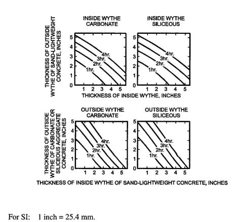
FIGURE 721.2.1.2 FIRE-RESISTANCE RATINGS OF TWO-WYTHE CONCRETE WALLS
721.2.1.1.3 Tapered cross sections. The thickness of panels with tapered cross sections shall be that determined at a distance 2t or 6 inches (152 mm), whichever is less, from the point of minimum thickness, where t is the minimum thickness.
721.2.1.1.4 Ribbed or undulating surfaces. The equivalent thickness of panels with ribbed or undulating surfaces shall be determined by one of the following expressions:
For s≥4t, the thickness to be used shall be t
For s≤2t, the thickness to be used shall be te
For 4t>s>2t, the thickness to be used shall be
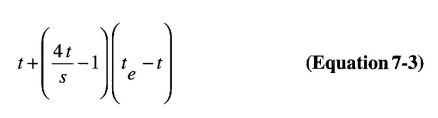
where:
s = Spacing of ribs or undulations.
t = Minimum thickness.
te = Equivalent thickness of the panel calculated as the not cross-sectional area of the panel divided by the width, in which the maximum thickness used in the calculation shall not exceed 2t.
721.2.1.2 Multiwythe walls. For walls that consist of two wythes of different types of concrete, the fire-resistance ratings shall be permitted to be determined from Figure 721.2.1.2.
225| TYPE OF MATERIAL | THICKNESS OF MATERIAL(inches) | |||||||||||
|---|---|---|---|---|---|---|---|---|---|---|---|---|
| 1½ | 2 | 2½ | 3 | 3½ | 4 | 4½ | 5 | 5½ | 6 | 6½ | 7 | |
| Siliceous aggregate concrete | 5.3 | 6.5 | 8.1 | 9.5 | 11.3 | 13.0 | 14.9 | 16.9 | 18.8 | 20.7 | 22.8 | 25.1 |
| Carbonate aggregate concrete | 5.5 | 7.1 | 8.9 | 10.4 | 12.0 | 14.0 | 16.2 | 18.1 | 20.3 | 21.9 | 24.7 | 27.2c |
| Sand-lightweight concrete | 6.5 | 8.2 | 10.5 | 12.8 | 15.5 | 18.1 | 20.7 | 23.3 | 26.0 c | Note c | Note c | Note c |
| Lightweight concrete | 6.6 | 8.8 | 11.2 | 13.7 | 16.5 | 19.1 | 21.9 | 24.7 | 27.8c | Note c | Note c | Note c |
| Insulating concretea | 9.3 | 13.3 | 16.6 | 18.3 | 23.1 | 26.5c | Note c | Note c | Note c | Note c | Note c | Note c |
| Airspaceb | — | — | — | — | — | — | — | — | — | — | — | — |
| For SI: 1 inch = 25.4 mm. 1 pound per cubic foot = 16.02 kg/m3 | ||||||||||||
| a. Dry unit weight of 35 pcf or less and consisting of cellular, perlite or vermiculite concrete. | ||||||||||||
| b. The Rn 0.59 value for two ½ " to 3½ " airspace is 3.3. The Rn 0.59 value for two ½" to 3½" airspaces is 6.7. | ||||||||||||
| c. The fire-resistance rating for this thickness exceeds 4 hours. | ||||||||||||
721.2.1.2.1 Two or more wythes. The fire-resistance rating for wall panels consisting of two or more wythes shall be permitted to be determined by the formula:
R=(R10.59+R20.59+…+Rn0.59)1.7
Equation 7- 4)
where:
R = The fire endurance of the assembly, minutes.
R1, R 2, and Rn = The fire endurances of the individual wythes, minutes. Values of Rn0.59 for use in Equation 7-4 are given in Table 721.2.1.2(1). Calculated fire-resistance ratings are shown in Table 721.2.1.2(2).
| Ra, MINUTES | R0.59 |
|---|---|
| 60 | 11.20 |
| 120 | 16.85 |
| 180 | 21.41 |
| 240 | 25.37 |
| a. Based on Equation 7-4. | |
721.2.1.2.2 Foam plastic insulation. The fire-resis -tance ratings of precast concrete wall panels consisting of a layer of foam plastic insulation sandwiched between two wythes of concrete shall be permitted to be determined by use of Equation 7-4. Foam plastic insulation with a total thickness of less than 1 inch (25 mm) shall be disregarded. The Rn value for thickness of foam plastic insulation of 1 inch (25 mm) or greater, for use in the calculation, is 5 minutes' therefore Rn0.59=2.5.
721.2.1.3 Joints between precast wall panels. Joints between precast concrete wall panels which are not insulated as required by this section shall be considered as openings in walls. Uninsulated joints shall be included in determining the percentage of openings permitted by Table 705.8. Where openings are not permitted or are required by this code to be protected, the provisions of this section shall be used to determine the amount of joint insulation required. Insulated joints shall not be considered openings for purposes of determining compliance with the allowable percentage of openings in Table 705.8.
721.2.1.3.1 Ceramic fiber joint protection. Figure 721.2.1.3.1 shows thicknesses of ceramic fiber blankets to be used to insulate joints between precast concrete wall panels for various panel thicknesses and for joint widths of 3/8 inch (9.5 mm) and 1 inch (25 mm) for fire-resistance ratings of 1 hour to 4 hours. For joint widths between 3/8 inch (9.5 mm) and 1 inch (25 mm), the thickness of ceramic fiber blanket is allowed to be determined by direct interpolation. Other tested and labeled materials are acceptable in place of ceramic fiber blankets.
721.2.1.4 Walls with gypsum wallboard or plaster finishes. The fire-resistance rating of cast-in-place or precast concrete walls with finishes of gypsum wallboard or plaster applied to one or both sides shall be permitted to be calculated in accordance with the provisions of this section.
721.2.1.4.1 Nonfire-exposed side. Where the finish of gypsum wallboard or plaster is applied to the side of the wall not exposed to fire, the contribution of the finish to the total fire-resistance rating shall be determined as follows: The thickness of the finish shall first be corrected by multiplying the actual thickness of the finish by the applicable factor determined from Table 721.2.1.4(1) based on the type of aggregate in the concrete. The corrected thickness of finish shall then be added to the actual or equivalent thickness of concrete and fire-resistance rating of the concrete and finish determined from Table 721.2.1.1, Figure 721.2.1.2 or Table 721.2.1.2(1).
226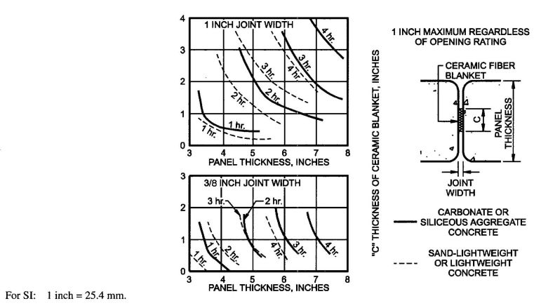
FIGURE 721.2.1.3.1 CERAMIC FIBER JOINT PROTECTION
721.2.1.4.2 Fire-exposed side. Where gypsum wall -board or plaster is applied to the fire-exposed side of the wall, the contribution of the finish to the total fire-resistance rating shall be determined as follows: The time assigned to the finish as established by Table 721.2.1.4(2) shall be added to the fire-resistance rating determined from Table 721.2.1.1 or Figure 721.2.1.2, or Table 721.2.1.2 (1) for the concrete alone, or to the rating determined in Section 721.2.1.4.1 for the concrete and finish on the nonfire-exposed side.
721.2.1.4.3 Nonsymmetrical assemblies. For a wall having no finish on one side or different types or thicknesses of finish on each side, the calculation procedures of Sections 721.2.1.4.1 and 721.2.1.4.2 shall be performed twice, assuming either side of the wall to be the fire-exposed side. The fire-resistance rating of the wall shall not exceed the lower of the two values.
Exception: For an exterior wall with a fire separation distance greater than 5 feet (1524 mm) the fire shall be assumed to occur on the interior side only.
721.2.1.4.4 Minimum concrete fire-resistance rating. Where finishes applied to one or both sides of a concrete wall contribute to the fire-resistance rating, the concrete alone shall provide not less than one-half of the total required fire-resistance rating. Additionally, the contribution to the fire - resistance rating. of the finish on the nonfire-exposed side of a load-bearing wall shall not exceed one-half the contribution of the concrete alone.
721.2.1.4.5 Concrete finishes. Finishes on concrete walls that are assumed to contribute to the total fire-resistance rating of the wall shall comply with the installation requirements of Section 721.3.2.5.
721.2.2 Concrete floor and roof slabs. Reinforced and prestressed floors and roofs shall comply with Section 721.2.2.1. Multicourse floors and roofs shall comply with Sections 721.2.2.2 and 721.2.2.3, respectively.
721.2.2.1 Reinforced and prestressed floors and roofs. The minimum thicknesses of reinforced and prestressed concrete floor or roof slabs for fire-resistance ratings of 1 hour to 4 hours are shown in Table 721.2.2.1.
| CONCRETE TYPE | FIRE -RESISTANCE RATING (hour) | ||||
|---|---|---|---|---|---|
| 1 | 1½ | 2 | 3 | 4 | |
| Siliceous | 3.5 | 4.3 | 5.0 | 6.2 | 7.0 |
| Carbonate | 3.2 | 4.0 | 4.6 | 5.7 | 6.6 |
| Sand-lightweight | 2.7 | 3.3 | 3.8 | 4.6 | 5.4 |
| Lightweight | 2.5 | 3.1 | 3.6 | 4.4 | 5.1 |
| For SI: 1 inch =25.4 mm. | |||||
721.2.2.1.1 Hollow-core prestressed slabs. For hollow-core prestressed concrete slabs in which the cores are of constant cross section throughout the length, the equivalent thickness shall be permitted to be obtained by dividing the net cross-sectional area of the slab including grout in the joints, by its width.
721.2.2.1.2 Slabs with sloping soffits. The thickness of slabs with sloping soffits (see Figure 721.2.2.1.2) shall be determined at a distance 2t or 6 inches (152 mm), whichever is less, from the point of minimum thickness, where t is the minimum thickness.
227| TYPE OF FINISH APPLIED TO CONCRETE OR CONCRETE MASONRY WALL | TYPE OF AGGREGATE USED IN CONCRETE OR CONCRETE MASONRY | |||
|---|---|---|---|---|
| Concrete: siliceous or carbonate Concrete Masonry: siliceous or carbonate; solid clay brick | Concrete: sand-lightweight Concrete Masonry: clay tile; hollow clay brick; concrete masonry units of expanded shale and <20% sand | Concrete: lightweight Concrete Masonry: concrete masonry units of expanded shale, expanded clay, expanded slag, or pumice < 20% sand | Concrete Masonry: concrete masonry units of expanded slag, expanded clay, or pumice | |
| Portland cement-sand plaster | 1.00 | 0.75a | 0.75a | 0.50a |
| Gypsum-sand plaster | 1.25 | 1.00 | 1.00 | 1.00 |
| Gypsum-vermiculite or perlite plaster | 1.75 | 1.50 | 1.25 | 1.25 |
| Gypsum wallboard | 3.00 | 2.25 | 2.25 | 2.25 |
| For SI: 1 inch = 25.4 mm. | ||||
| a. For portland cement-sand plaster 5/8 inch or less in thickness and applied directly to the concrete or concrete masonry on the nonfire-exposed side of the wall, the multiplying factor shall be 1.00. | ||||
| FINISH DESCRIPTION | TIME (minute) |
|---|---|
| Gypsum wallboard | |
| 3/8 inch | 10 |
| 1/2 inch | 15 |
| 5/8 inch | 20 |
| 2 layers of 3/8 inch | 25 |
| 1 layer 3/8 inch, 1 layer 1/2 inch | 35 |
| 2 layer 1/2 inch | 40 |
| Type X gypsum wallboard | |
| 1/2 inch | 25 |
| 5/8 inch | 40 |
| Portland cement-sand plaster applied directly to concrete masonry | See Note a |
| Portland cement-sand plaster on metal lath | |
| 3/4 inch | 20 |
| 7/8 inch | 25 |
| 1 inch | 30 |
| Gypsum sand plaster on 3/8-inch gypsum lath | |
| 1/2 inch | 35 |
| 5/8 inch | 40 |
| 3/4 inch | 50 |
| Gypsum sand plaster on metal lath | |
| 3/4 inch | 50 |
| 7/8 inch | 60 |
| 1 inch | 80 |
| For SI: 1 inch=25.4 mm. | |
| a. The actual thickness of portland cement-sand plaster, provided it is 5/8 inch or less in thickness, shall be permitted to be included in determining the equivalent thickness of the masonry for use in Table 721.3.2. | |
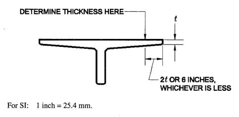
FIGURE 721.2.2.1.2 DETERMINATION OF SLAB THICKNESS FOR SLOPING SOFFITS
721.2.2.1.3 Slabs with ribbed soffits. The thickness of slabs with ribbed or undulating soffits (see Figure 721.2.2.1.3) shall be determined by one of the following expressions, whichever is applicable:
For s > 4t, the thickness to be used shall be t
For s ≤ 2t, the thickness to be used shall be te
For 4t > s > 2t, the thickness to be used shall be
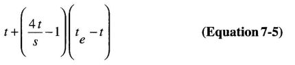
where:
s = Spacing of ribs or undulations.
t = Minimum thickness.
te = Equivalent thickness of the slab calculated as the net area of the slab divided by the width, in which the maximum thickness used in the calculation shall not exceed 2t.
For SI: 1 inch=25.4 mm.
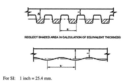
FIGURE 721.2.2.1.3 SLABS WITH RIBBED OR UNDULATING SOFFITS
721.2.2.2 Multicourse floors. The fire-resistance ratings of floors that consist of a base slab of concrete with a topping (overlay) of a different type of concrete shall comply with Figure 721.2.2.2.
721.2.2.3 Multicourse roofs. The fire-resistance ratings of roofs which consist of a base slab of concrete with a topping (overlay) of an insulating concrete or with an insulating board and build-up roofing shall comply with Figures 721.2.2.3(1) and 721.2.2.3(2).
721.2.2.3.1 Heat transfer. For the transfer of heat, three-ply built-up roofing contributes 10 minutes to the fire-resistance rating. The fire-resistance rating for concrete assemblies such as those shown in Figure 721.2.2.3(1) shall be increased by 10 minutes. This increase is not applicable to those shown in Figure 721.2.2.3(2).
721.2.2.4 Joints in precast slabs. Joints between adjacent precast concrete slabs need not be considered in calculating the slab thickness provided that a concrete topping at least 1 inch (25 mm) thick is used. Where no concrete topping is used, joints must be grouted to a depth of at least one-third the slab thickness at the joint, but not less than 1 inch (25 mm), or the joints must be made fire resistant by other approved methods.
721.2.3 Concrete cover over reinforcement. The minimum thickness of concrete cover over reinforcement in concrete slabs, reinforced beams and prestressed beams shall comply with this section.
721.2.3.1 Slab cover. The minimum thickness of concrete cover to the positive moment reinforcement shall comply with Table 721.2.3(1) for reinforced concrete and Table 721.2.3.(2) for prestressed concrete. These tables are applicable for solid or hollow-core one-way or two-way slabs with flat undersurfaces. These tables are applicable to slabs that are either cast in place or precast. For precast prestressed concrete not covered elsewhere, the procedures contained in PCI MNL 124 shall be acceptable.
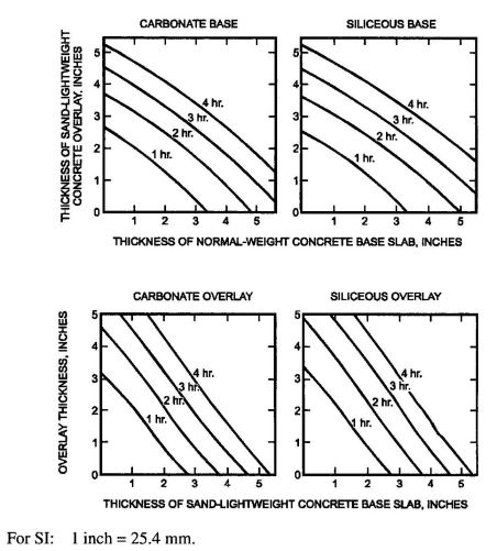
FIGURE 721.2.2.2 FIRE-RESISTANCE RATINGS FOR TWO-COURSE CONCRETE FLOORS
229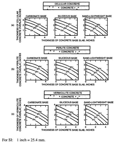
FIGURE 721.2.2.3(1)FIRE-RESISTANCE RATINGS FOR CONCRETE ROOF ASSEMBLIES
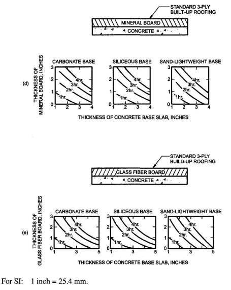
FIGURE 721.2.2.3(2)FIRE-RESISTANCE RATINGS FOR CONCRETE ROOF ASSEMBLIES
721.2.3.2 Reinforced beam cover. The minimum thickness of concrete cover to the positive moment reinforcement (bottom steel) for reinforced concrete beams is shown in Table 721.2.3(3) for fire-resistance ratings of 1 hour to 4 hours.
721.2.3.3 Prestressed beam cover. The minimum thickness of concrete cover to the positive moment prestressing tendons (bottom steel) for restrained and unrestrained prestressed concrete beams and stemmed units shall comply with the values shown in Tables 721.2.3(4) and 721.2.3(5) for fire-resistance ratings of 1 hour to 4 hours. Values in Table 721.2.3(4) apply to beams 8 inches (203 mm) or greater in width. Values in Table 721.2.3(5) apply to beams or stems of any width. provided the cross-section area is not less than 40 square inches (25 806 mm2). In case of differences between the values determined from Table 721.2.3(4) or 721.2.3(5), it is permitted to use the smaller value. The concrete cover shall be calculated in accordance with Section 721.2.3.3.1. The minimum concrete cover for nonprestressed reinforcement in prestressed concrete beams shall comply with Section 721.2.3.2.
721.2.3.3.1 Calculating concrete cover. The concrete cover for an individual tendon is the minimum thickness of concrete between the surface of the tendon and the fire-exposed surface of the beam, except that for ungrouted ducts, the assumed cover thickness is the minimum thickness of concrete between the surface of the duct and the fire-exposed surface of the beam. For beams in which two or more tendons are used, the cover is assumed to be the average of the minimum cover of the individual tendons. For corner tendons (tendons equal distance from the bottom and side), the minimum cover used in the calculation shall be one-half the actual value. For stemmed members with two or more prestressing tendons located along the vertical centerline of the stem, the average cover shall be the distance from the bottom of the member to the centroid of the tendons. The actual cover for any individual tendon shall not be less than one-half the smaller value shown in Tables 721.2.3(4) and 721.2.3(5), or 1 inch (25 mm), whichever is greater.
721.2.4 Concrete columns. Concrete columns shall comply with this section.
| TYPES OF CONCRETE | FIRE-RESISTANCE RATING(hours) | ||||
|---|---|---|---|---|---|
| 1 | 1½ | 2a | 3a | 4b | |
| Siliceous | 8 | 9 | 10 | 12 | 14 |
| Carbonate | 8 | 9 | 10 | 11 | 12 |
| Sand-lightweight | 8 | 8½ | 9 | 10½ | 12 |
| For SI: 1 inch=25 mm. | |||||
| a. The minimum dimension is permitted to be reduced to 8 inches for rectangular columns with two parallel sides at least 36 inches in length. | |||||
| b. The minimum dimension is permitted to be reduced to 10 inches for rectangular columns with two parallel sides at least 36 inches in length. | |||||
| CONCRETE AGGREGATE TYPE | FIRE-RESISTANCE RATING (hours) | |||||||||
|---|---|---|---|---|---|---|---|---|---|---|
| Restrained | Unrestrained | |||||||||
| 1 | 1½ | 2 | 3 | 4 | 1 | 1½ | 2 | 3 | 4 | |
| Siliceous | ¾ | ¾ | ¾ | ¾ | ¾ | ¾ | ¾ | 1 | 1¼ | 1 5/8 |
| Carbonate | ¾ | ¾ | ¾ | ¾ | ¾ | ¾ | ¾ | ¾ | 1¼ | 1¼ |
| Sand-lightweight or lightweight | ¾ | ¾ | ¾ | ¾ | ¾ | ¾ | ¾ | ¾ | 1¼ | 1¼ |
| For SI: 1 inch = 25.4 mm. | ||||||||||
| CONCRETE AGGREGATE TYPE | FIRE-RESISTANCE RATING (hours) | |||||||||
|---|---|---|---|---|---|---|---|---|---|---|
| Restrained | Unrestrained | |||||||||
| 1 | 1½ | 2 | 3 | 4 | 1 | 1½ | 2 | 3 | 4 | |
| Siliceous | ¾ | ¾ | ¾ | ¾ | ¾ | 11/8 | 1½ | 1¾ | 23/8 | 2¾ |
| Carbonate | ¾ | ¾ | ¾ | ¾ | ¾ | 1 | 13/8 | 15/8 | 21/8 | 2¼ |
| Sand-lightweight or light weight | ¾ | ¾ | ¾ | ¾ | ¾ | 1 | 13/8 | 1½ | 2 | 2¼ |
| For SI: 1 inch = 25.4 mm. | ||||||||||
| RESTRAINED OR UNRESTRAINEDb | BEAM WIDTHb(inches) | FIRE-RESISTANCE RATING (hours) | ||||
|---|---|---|---|---|---|---|
| 1 | 1½ | 2 | 3 | 4 | ||
| Restrained | 5 | ¾ | ¾ | ¾ | 1a | 1¼a |
| 7 | ¾ | ¾ | ¾ | ¾ | ¾ | |
| ≥10 | ¾ | ¾ | ¾ | ¾ | ¾ | |
| Unrestrained | 5 | ¾ | 1 | 1¼ | — | — |
| 7 | ¾ | ¾ | ¾ | 1¾ | 3 | |
| ≥10 | ¾ | ¾ | ¾ | 1 | 1¾ | |
| For SI: 1 inch = 25.4 mm, 1 foot = 304.8 mm. | ||||||
| a. Tabulated values for restrained assemblies apply to beams spaced more than 4 feet on center. For restrained beams spaced 4 feet or less on center, minimum cover of ¾ inch is adequate for ratings of 4 hours or less. | ||||||
| b. For beam widths between the tabulated values, the minimum cover thickness can be determined by direct interpolation. | ||||||
| c. The cover for an individual reinforcing bar is the minimum thickness of concrete between the surface of the bar and the fire-exposed surface of the beam. For beams in which several bars are used, the cover for corner bars used in the calculation shall be reduced to one-half of the actual value. The cover for an individual bar must be not less than one-half of the value given in Table 721.2.3(3) nor less than ¾ inch. | ||||||
| RESTRAINED OR UNRESTRAINEDa | CONCRETE AGGREGATE TYPE | BEAM WIDTHb(inches) | FIRE-RESISTANCE RATING (hours) | ||||
|---|---|---|---|---|---|---|---|
| 1 | 1½ | 2 | 3 | 4 | |||
| Restrained | Carbonate or siliceous | 8 | 1½ | 1½ | 1½ | 1¾a | 2½a |
| Carbonate or siliceous | ≥12 | 1½ | 1½ | 1½ | 1½ | 17/8a | |
| Sand lightweight | 8 | 1½ | 1½ | 1½ | 1½ | 2a | |
| Sand lightweight | ≥12 | 1½ | 1½ | 1½ | 1½ | 15/8a | |
| Unrestrained | Carbonate or siliceous | 8 | 1½ | 1¾ | 2½ | 5c | — |
| Carbonate or siliceous | ≥12 | 1½ | 1½ | 17/8a | 2½ | 3 | |
| Sand lightweight | 8 | 1½ | 1½ | 2 | 3¼ | — | |
| Sand lightweight | ≥12 | 1½ | 1½ | 15/8 | 2 | 2½ | |
| For SI: 1 inch = 25.4 mm, 1 foot = 304.8 mm. | |||||||
| a. Tabulated values for restrained assemblies apply to beams spaced more than 4 feet on center. For restrained beams spaced 4 feet or less on center, minimum cover of ¾ inch is adequate for 4-hours ratings or less. | |||||||
| b. For beam widths between 8 inches and 12 inches, minimum cover thickness can be determined by direct interpolation. | |||||||
| c. Not practical for 8-inch-wide beam but shown for purposes of interpolation. | |||||||
| RESTRAINED OR UNRESTRAINEDa | CONCRETE AGGREGATE TYPE | BEAM AREAb A (square inches) | FIRE-RESISTANCE RATING (hours) | ||||
|---|---|---|---|---|---|---|---|
| 1 | 1½ | 2 | 3 | 4 | |||
| Restrained | All | 40<A≤150 | 1½ | 1½ | 2 | 2½ | — |
| Carbonate or siliceous | 150<A≤300 | 1½ | 1½ | 1½ | 1¾ | 2½ | |
| 300<A | 1½ | 1½ | 1½ | 1½ | 2 | ||
| Sand lightweight | 150<A | 1½ | 1½ | 1½ | 1½ | 2 | |
| Unrestrained | All | 40≤A≤150 | 2 | 2½ | — | — | — |
| Carbonate or siliceous | 150<A≤300 | 1½ | 1¾ | 2½ | — | — | |
| 300<A | 1½ | 1½ | 2 | 3c | 4c | ||
| Sand lightweight | 150<A | 1½ | 1½ | 2 | 3c | 4c | |
| For SI: 1 inch = 25.4 mm, 1 foot = 304.8 mm. | |||||||
| a. Tabulated values for restrained assemblies apply to beams spaced more than 4 feet on center. For restrained beams spaced 4 feet or less on center, minimum cover of ¾ inch is adequate for 4-hour ratings or less. | |||||||
| b. The cross-sectional area of a stem is permitted to include a portion of the area in the flange, provided the width of the flange used in the calculation does not exceed three times the average width of the stem. | |||||||
| c. U-shaped or hooped stirrups spaced not to exceed the depth of the member and having a minimum cover of 1 inch shall be provided. | |||||||
| TYPE OF AGGREGATE | FIRE-RESISTANCE RATING (hours) | ||||||||||||||
|---|---|---|---|---|---|---|---|---|---|---|---|---|---|---|---|
| ½ | ¾ | 1 | 1¼ | 1½ | 1¾ | 2 | 2¼ | 2½ | 2¾ | 3 | 3¼ | 3½ | 3¾ | 4 | |
| Pumice or expanded slag | 1.5 | 1.9 | 2.1 | 2.5 | 2.7 | 3.0 | 3.2 | 3.4 | 3.6 | 3.8 | 4.0 | 4.2 | 4.4 | 4.5 | 4.7 |
| Expanded shale, clay or slate | 1.8 | 2.2 | 2.6 | 2.9 | 3.3 | 3.4 | 3.6 | 3.8 | 4.0 | 4.2 | 4.4 | 4.6 | 4.8 | 4.9 | 5.1 |
| Limestone, cinders or unexpanded slag | 1.9 | 2.3 | 2.7 | 3.1 | 3.4 | 3.7 | 4.0 | 4.3 | 4.5 | 4.8 | 5.0 | 5.2 | 5.5 | 5.7 | 5.9 |
| Calcareous or siliceous graved | 2.0 | 2.4 | 2.8 | 3.2 | 3.6 | 3.9 | 4.2 | 4.5 | 4.8 | 5.0 | 5.3 | 5.5 | 5.8 | 6.0 | 6.2 |
| For SI: 1 inch = 25.4 mm. | |||||||||||||||
| a. Values between those shown in the table can be determined by direct interpolation. | |||||||||||||||
| b. Where combustible members are framed into the wall, the thickness of solid material between the end of each member and the opposite face of the wall, or between members set in from opposite sides, shall not be less than 93 percent of the thickness shown in the table. | |||||||||||||||
| c. Requirements of ASTM C 55, ASTM C 73, ASTM C 90 or ASTM C 744 shall apply. | |||||||||||||||
| d. Minimum required equivalent thickness corresponding to the hourly fire-resistance rating for units with a combination of aggregate shall be determined by linear interpolation based on the percent by volume of each aggregate used in manufacture. | |||||||||||||||
721.2.4.1 Minimum size. The minimum overall dimensions of reinforced concrete columns for fire-resistance ratings of 1 hour to 4 hours for exposure to fire on all sides shall comply with this section.
721.2.4.1.1 Concrete strength less than or equal to 12,000 psi. For columns made with concrete having a specified compressive strength, f′c, of less than or equal to 12,000 psi (82.7 MPa), the minimum dimension shall comply with Table 721.2.4.
721.2.4.1.2 Concrete strength greater than 12,000 psi. For columns made with concrete having a specified compressive strength, f′c, greater than 12,000 psi (82.7 MPa), for fire-resistance ratings of 1 hour to 4 hours the minimum dimension shall be 24 inches (610 mm).
721.2.4.2 Minimum cover for R/C columns. The minimum thickness of concrete cover to the main longitudinal reinforcement in columns, regardless of the type of aggregate used in the concrete and the specified compressive strength of concrete, f′c, shall not be less than 1 inch (25 mm) times the number of hours of required fire resistance or 2 inches (51 mm), whichever is less.
721.2.4.3 Tie and spiral reinforcement. For concrete columns made with concrete having a specified compressive strength, f′c, greater than 12,000 psi (82.7 MPa), tie and spiral reinforcement shall comply with the following:
The hook extension at the free end of ties and spirals shall be the larger of six bar diameters and the extension required by Section 7.1.3 of ACI 318. Hooks shall project into the core of the column.
| MATERIAL TYPE | MINIMUM REQUIRED EQUIVALENT THICKNESS FOR FIRE RESISTANCEa, b, c(inches) | |||
|---|---|---|---|---|
| 1 hour | 2 hour | 3 hour | 4 hour | |
| Solid brick of clay or shaled | 2.7 | 3.8 | 4.9 | 6.0 |
| Hollow brick or tile of clay or shale, unfilled | 2.3 | 3.4 | 4.3 | 5.0 |
| Hollow brick or tile of clay or shale, grouted or filled with materials specified in Section 721.4.1.1.3 | 3.0 | 4.4 | 5.5 | 6.6 |
| For SI: 1 inch = 25.4 mm. | ||||
| a. Equivalent thickness as determined from Section 721.4.1.1. | ||||
| b. Calculated fire resistance between the hourly increments listed shall be determined by linear interpolation. | ||||
| c. Where combustible members are framed in the wall, the thickness of solid material between the end of each members and the opposite face of the wall, or between members set in from opposite sides, shall not be less than 93 percent of the thickness shown. | ||||
| d. For units in which the net cross-sectional area of cored brick in any plane parallel to the surface containing the cores is at least 75 percent of the gross cross-sectional area measured in the same plane. | ||||
| WALL OR PARTITION ASSEMBLY | PLASTER SIDE EXPOSED (hours) | BRICK FACED SIDE EXPOSED (hours) |
|---|---|---|
| Outside facing of steel studs: ½″ wood fiberboard sheathing next to studs, ¾″ airspace formed with ¾″ × 15/8″ wood strips placed over the fiberboard and secured to the studs; metal or wire lath nailed to such strips, 3¾″ brick veneer held in place by filling ¾″ airspace between the brick and lath with mortar. Inside facing of studs:¾″ unsanded gypsum plaster on metal or wire lath attached to 5/16″ wood strips secured to edges of the studs. | 1.5 | 4 |
| Outside facing of steel studs: 1″ insulation board sheathing attached to studs, 1″ airspace, and 3¾″ brick veneer attached to steel frame with metal ties every 5th course. Inside facing of studs: 7/8″ sanded gypsum plaster (1:2 mix) applied on metal or wire lath attached directly to the studs. | 1.5 | 4 |
| Same as above except use 7/8″ vermiculite—gypsum plaster or 1″ sanded gypsum plaster (1:2 mix) applied to metal or wire. | 2 | 4 |
| Outside facing of steel studs: ½″—gypsum sheathing board, attached to studs, and 3¾″ brick veneer attached to steel frame with metal ties every 5th course. Inside facing of studs: ½″ sanded gypsum plaster (1:2 mix) applied to ½″ perforated gypsum lath securely attached to studs and having strips of metal lath 3 inches wide applied to all horizontal joints of gypsum lath. | 2 | 4 |
| For SI: 1 inch = 25.4 mm. | ||
721.2.4.4 Columns built into walls. The minimum dimensions of Table 721.2.4 do not apply to a reinforced concrete column that is built into a concrete or masonry wall provided all of the following are met:
Where openings in the wall are not protected as required by Section 715.4, the minimum dimension of columns required to have a fire-resistance rating of 3 hours or less shall be 8 inches (203 mm), and 10 inches (254 mm) for columns required to have a fire-resistance rating of 4 hours, regardless of the type of aggregate used in the concrete.
721.2.4.5 Precast cover units for steel columns. See Section 721.5.1.4.
721.3 Concrete masonry. The provisions of this section contain procedures by which the fire-resistance ratings of concrete masonry are established by calculations.
721.3.1 Equivalent thickness. The equivalent thickness of concrete masonry construction shall be determined in accordance with the provisions of this section.
721.3.1.1 Concrete masonry unit plus finishes. The equivalent thickness of concrete masonry assemblies, Tea, shall be computed as the sum of the equivalent thickness of the concrete masonry unit, Te, as determined by
233Section 721.3.1.2, 721.3.1.3 or 721.3.1.4, plus the equivalent thickness of finishes,Tef, determined in accordance with Section 721.3.2:

721.3.1.2 Ungrouted or partially grouted construction. Te shall be the value obtained for the concrete masonry unit determined in accordance with ASTM C 140.
721.3.1.3 Solid grouted construction. The equivalent thickness, Te, of solid grouted concrete masonry units is the actual thickness of the unit.
721.3.1.4 Airspaces and cells filled with loose-fill material. The equivalent thickness of completely filled hollow concrete masonry is the actual thickness of the unit when loose-fill materials are: sand, pea gravel, crushed stone, or slag that meet ASTM C 33 requirements; pumice, scoria, expanded shale, expanded clay, expanded slate, expanded slag, expanded fly ash, or cinders that comply with ASTM C 331; or perlite or vermiculite meeting the requirements of ASTM C 549 and ASTM C 516, respectively.
721.3.2 Concrete masonry walls. The fire-resistance rating of walls and partitions constructed of concrete masonry units shall be determined from Table 721.3.2. The rating shall be based on the equivalent thickness of the masonry and type of aggregate used.
721.3.2.1 Finish on nonfire-exposed side. Where plaster or gypsum wallboard is applied to the side of the wall not exposed to fire, the contribution of the finish to the total fire-resistance rating shall be determined as follows: The thickness of gypsum wallboard or plaster shall be corrected by multiplying the actual thickness of the finish by applicable factor determined from Table 721.2.1.4(1). This corrected thickness of finish shall be added to the equivalent thickness of masonry and the fire-resistance rating of the masonry and finish determined from Table 721.3.2.
721.3.2.2 Finish on fire-exposed side. Where plaster or gypsum wallboard is applied to the fire-exposed side of the wall, the contribution of the finish to the total fire-resistance rating shall be determined as follows: The time assigned to the finish as established by Table 721.2.1.4(2) shall be added to the fire-resistance rating determined in Section 721.3.2 for the masonry alone, or in Section 721.3.2.1 for the masonry and finish on the nonfire-exposed side.
721.3.2.3 Nonsymmetrical assemblies. For a wall having no finish on one side or having different types or thicknesses of finish on each side, the calculation procedures of this section shall be performed twice, assuming either side of the wall to be the fire-exposed side. The fire-resistance rating of the wall shall not exceed the lower of the two values calculated.
Exception: For exterior walls with a fire separation distance greater than 5 feet (1524 mm) the fire shall be assumed to occur on the interior side only.
721.3.2.4 Minimum concrete masonry fire-resistance rating. Where the finish applied to a concrete masonry wall contributes to its fire-resistance rating, the masonry alone shall provide not less than one-half the total required fire-resistance rating.
721.3.2.5 Attachment of finishes. Installation of finishes shall be as follows:
721.3.3 Multiwythe masonry walls. The fire-resistance rating of wall assemblies constructed of multiple wythes of masonry materials shall be permitted to be based on the fire-resistance rating period of each wythe and the continuous airspace between each wythe in accordance with the following formula:
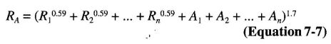
where:
RA = Fire-resistance rating of the assembly (hours).
R1R2…, Rn = Fire-resistance rating of wythes for 1, 2, n (hours), respectively.
A1, A2, …., An = 0.30, factor for each continuous airspace for 1, 2, …n, respectively, having a depth of ½ inch (12.7 mm) or more between wythes.
721.3.4 Concrete masonry lintels. Fire-resistance ratings for concrete masonry lintels shall be determined based upon the nominal thickness of the lintel and the minimum thickness of concrete masonry or concrete, or any combination thereof, covering the main reinforcing bars, as determined according to Table 721.3.4, or by approved alternate methods.
| NOMINAL WIDTH OF LINTEL (inches) | FIRE-RESISTANCE RATING (hours) | |||
|---|---|---|---|---|
| 1 | 2 | 3 | 4 | |
| 6 | 1½ | 2 | — | — |
| 8 | 1½ | 1½ | 1¾ | 3 |
| 10 or greater | 1½ | 1½ | 1½ | 1¾ |
| For SI: 1 inch = 25.4 mm. | ||||
721.3.5 Concrete masonry columns. The fire-resistance rating of concrete masonry columns shall be determined based upon the least plan dimension of the column in accordance with Table 721.3.5 or by approved alternate methods.
234| FIRE-RESISTANCE RATING (hours) | |||
|---|---|---|---|
| 1 | 2 | 3 | 4 |
| 8 inches | 10 inches | 12 inches | 14 inches |
| For SI: 1 inch = 25.4 mm. | |||
721.4 Clay brick and tile masonry. The provisions of this section contain procedures by which the fire-resistance ratings of clay brick and tile masonry are established by calculations.
721.4.1 Masonry walls. The fire-resistance rating of masonry walls shall be based upon the equivalent thickness as calculated in accordance with this section. The calculation shall take into account finishes applied to the wall and airspaces between wythes in multiwythe construction.
721.4.1.1 Equivalent thickness. The fire-resistance ratings of walls or partitions constructed of solid or hollow clay masonry units shall be determined from Table 721.4.1(1) or 721.4.1(2). The equivalent thickness of the clay masonry unit shall be determined by Equation 7-8 when using Table 721.4.1(1). The fire-resistance rating determined from Table 721.4.1(1) shall be permitted to be used in the calculated fire-resistance rating procedure in Section 721.4.2.
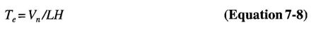
where:
Te = The equivalent thickness of the clay masonry unit (inches).
Vn = The net volume of the clay masonry unit (inch3).
L = The specified lenght of the clay masonry unit (inches).
H = The specified height of the clay masonry unit (inches).
721.4.1.1.1 Hollow clay units. The equivalent thickness, Te, shall be the value obtained for hollow clay units as determined in accordance with Equation 7-8. The net volume, Vn, of the units shall be determined using the gross volume and percentage of void area determined in accordance with ASTM C 67.
721.4.1.1.2 Solid grouted clay units. The equivalent thickness of solid grouted clay masonry units shall be taken as the actual thickness of the units.
721.4.1.1.3 Units with filled cores. The equivalent thickness of the hollow clay masonry units is the actual thickness of the unit when completely filled with loose-fill materials of: sand, pea gravel, crushed stone, or slag that meet ASTM C 33 requirements; pumice, scoria, expanded shale, expanded clay, expanded slate, expanded slag, expanded fly ash, or cinders in compliance with ASTM C 331; or perlite or vermiculite meeting the requirements of ASTM C 549 and ASTM C 516, respectively.
721.4.1.2 Plaster finishes. Where plaster is applied to the wall, the total fire-resistance rating shall be determined by the formula:
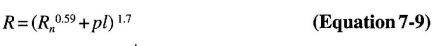
where:
R = The fire-resistance rating of the assembly (hours).
Rn = The fire-resistance rating of the individual wall (hours).
pl = Coefficient for thickness of plaster.
Values for R0.59n for use in Equation 7-9 are given in Table 721.4.1(3). Coefficients for thickness of plaster shall be selected from Table 721.4.1(4) based on the actual thickness of plaster applied to the wall or partition and whether one or two sides of the wall are plastered.
721.4.1.3 Multiwythe walls with airspace. Where a continuous airspace separates multiple wythes of the wall or partition, the total fire-resistance rating shall be determined by the formula:

where:
R = The fire-resistance rating of the assembly (hours).
R1, R2 and Rn = The fire-resistance rating of the individual wythes (hours).
as = Coefficient for continuous airspace.
Values for Rn0.59 for use in Equation 7-10 are given in Table 721.4.1(3). The coefficient for each continuous airspace of ½ inch to 3 ½ inches (12.7 to 89 mm) separating two individual wythes shall be 0.3.
| R0.59n | R (hours) | |
|---|---|---|
| 1 | 1.0 | |
| 2 | 1.50 | |
| 3 | 1.91 | |
| 4 | 2.27 | |
| For SI: 1 inch = 25.4 mm. | ||
| a. Values listed in table are for 1:3 sanded gypsum plaster. | ||
| THICKNESS OF PLASTER (inches) | ONE SIDE | TWO SIDE |
|---|---|---|
| ½ | 0.3 | 0.6 |
| 5/8 | 0.37 | 0.75 |
| ¾ | 0.45 | 0.90 |
| NOMINAL LINTEL WIDTH (inches) | MINIMUM LONGITUDINAL REINFORCEMENT COVER FOR FIRE RESISTANCE (inch) | |||
|---|---|---|---|---|
| 1 hour | 2 hour | 3 hour | 4 hour | |
| 6 | 1½ | 2 | NP | NP |
| 8 | 1½ | 1½ | 1¾ | 3 |
| 10 or more | 1½ | 1½ | 1½ | 1¾ |
| For SI: 1 inch = 25.4 mm. | ||||
| NP = Not permitted. | ||||
| COLUMN SIZE | FIRE-RESISTANCE RATING (hour) | |||
|---|---|---|---|---|
| 1 | 2 | 3 | 4 | |
| Minimum column dimension (inches) | 8 | 10 | 12 | 14 |
| For SI: 1 inch = 25.4 mm. | ||||
721.4.1.4 Nonsymmetrical assemblies. For a wall having no finish on one side or having different types or thicknesses of finish on each side, the calculation procedures of this section shall be performed twice, assuming either side to be the fire-exposed side of the wall. The fire resistance of the wall shall not exceed the lower of the two values determined.
Exception: For exterior walls with a fire separation distance greater than 5 feet (1524 mm), the fire shall be assumed to occur on the interior side only.
721.4.2 Multiwythe walls. The fire-resistance rating for walls or partitions consisting of two or more dissimilar wythes shall be permitted to be determined by the formula:

where:
R=The fire-resistance rating of the assembly (hours).
R1, R2 and Rn = The fire-resistance rating of the individual wythes (hours).
Values for Rn0.59 for use in Equation 7-11 are given in Table 721.4.1(3).
721.4.2.1 Multiwythe walls of different material. For walls that consist of two or more wythes of different materials (concrete or concrete masonry units) in combination with clay masonry units, the fire-resistance rating of the different materials shall be permitted to be determined from Table 721.2.1.1 for concrete; Table 721.3.2 for concrete masonry units or Table 721.4.1(1) or 721.4.1(2) for clay and tile masonry units.
721.4.3 Reinforced clay masonry lintels. Fire-resistance ratings for clay masonry lintels shall be determined based on the nominal width of the lintel and the minimum covering for the longitudinal reinforcement in accordance with Table 721.4.1(5).
721.4.4 Reinforced clay masonry columns. The fire-resistance ratings shall be determined based on the last plan dimension of the column in accordance with Table 721.4.1(6). The minimum cover for longitudinal reinforcement shall be 2 inches (51 mm).
721.5 Steel assemblies. The provisions of this section contain procedures by which the fire-resistance ratings of steel assemblies are established by calculations.
721.5.1 Structural steel columns. The fire-resistance ratings of steel columns shall be based on the size of the element and the type of protection provided in accordance with this section.
721.5.1.1 General. These procedures establish a basis for determining the fire resistance of column assemblies as a function of the thickness of fire-resistant material and, the weight, W, and heated perimeter, D, of steel columns. As used in these sections, W is the average weight of a structural steel column in pounds per linear foot. The heated perimeter, D, is the inside perimeter of the fire-resistant material in inches as illustrated in Figure 721.5.1(1).
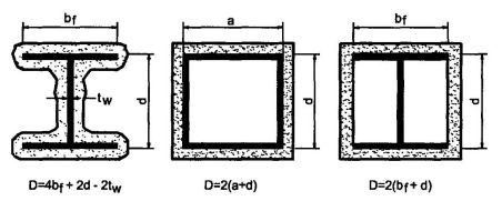
FIGURE 721.5.1 (1)
DETERMINATION OF THE HEATED PERIMETEROF STRUCTURAL STEEL COLUMNS
721.5.1.1.1 Nonload-bearing protection. The application of these procedures shall be limited to column assemblies in which the fire-resistant material is not designed to carry any of the load acting on the column.
721.5.1.1.2 Embedments. In the absence of substantiating fire-endurance test results, ducts, conduit, piping, and similar mechanical, electrical, and plumbing installations shall not be embedded in any required fire-resistant materials.
721.5.1.1.3 Weight-to-perimeter ratio. Table 721.5.1(1) contains weight-to-heated-perimeter ratios (W/D) for both contour and box fire-resistant profiles, for the wide flange shapes most often used as columns. For different fire-resistant protection profiles or column cross sections, the weight-to-heated-perimeter ratios (W/D) shall be determined in accordance with the definitions given in this section.
721.5.1.2 Gypsum wallboard protection. The fire resistance of structural steel columns with weight-to-heated-perimeter ratios(W/D) less than or equal to 3.65 and which are protected with Type X gypsum wallboard shall be permitted to be determined from the following expression:
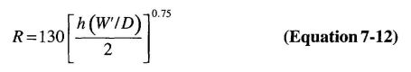
where:
R = Fire resistance (minutes).
h = Total thickness of gypsum wallboard (inches).
D = Heated perimeter of the structural steel column (inches).
W′ = Total weight of the structural steel column and gypsum wallboard protection (pounds per linear foot).
W′ = W + 50hD/144.
721.5.1.2.1 Attachment. The gypsum wallboard shall be supported as illustrated in either Figure 721.5.1(2) for fire-resistance ratings of 4 hours or less, or Figure 721.5.1(3) for fire-resistance ratings of 3 hours or less.
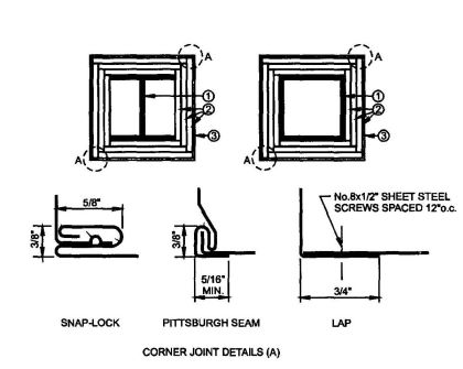
FIGURE 721.5.1(2)
GYPSUM WALLBOARD PROTECTED STRUCTURAL STEEL COLUMNS WITH SHEET STEEL COLUMN COVERS
For SI: 1 inch = 25.4 mm, 1 foot = 305 mm.
For fire-resistance ratings of 2 hours or less, column covers fabricated from 0.0269-inch minimum thickness galvanized or stainless steel shall be permitted to be erected with lap joints. The lap joints shall be permitted to be located anywhere around the perimeter of the column cover. The lap joints shall be secured with ½-inch-long No. 8 sheet metal screws spaced 12 inches on center.
The column covers shall be provided with a minimum expansion clearance of 1/8inch per linear foot between the ends of the cover and any restraining construction.
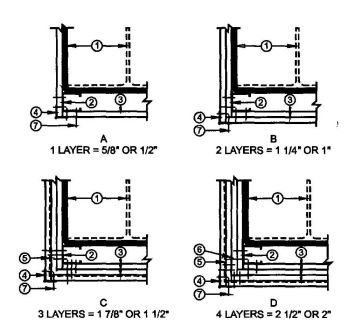
FIGURE 721.5.1 (3)
GYPSUM WALLBOARD PROTECTED STRUCTURAL STEEL COLUMNS WITH STEEL STUD/SCREW ATTACHMENT SYSTEM
For SI: 1 inch = 25.4 mm, 1 foot = -305 mm.
721.5.1.2.2 Gypsum wallboard equivalent to concrete. The determination of the fire resistance of structural steel columns from Figure 721.5.1(4) is permitted for various thicknesses of gypsum wallboard as a function of the weight-to-heated-perimeter ratio (W/D) of the column. For structural steel columns with weight-to-heated-perimeter ratios (W/D) greater than 3.65, the thickness of gypsum wallboard required for specified fire-resistance ratings shall be the same as the thickness determined for a W14×233 wide flange shape.
721.5.1.3 Sprayed fire-resistant materials. The fire resistance of wide-flange structural steel columns protected with sprayed fire-resistant materials, as illustrated in Figure 721.5.1(5), shall be permitted to be determined from the following expression:
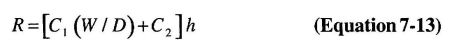
where:
R = Fire resistance (minutes).
237h = Thickness of sprayed fire-resistant material (inches).
D = Heated perimeter of the structural steel column (inches).
C1 and C2 = Material-dependent constants.
W = Weight of structural steel columns (pounds per linear foot).
The fire resistance of structural steel columns protected with intumescent or mastic fire-resistant coatings shall be determined on the basis of fire-resistance tests in accordance with Section 703.2.
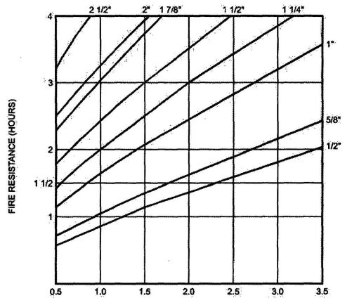
FIGURE 721.5.1(4)
FIRE RESISTANCE OF STRUCTURAL STEEL COLUMNS PROTECTED WITH VARIOUS THICKNESSES OF TYPE X GYPSUM WALLBOARD
For SI: 1 inch = 25.4 mm, 1 pound per linear foot/inch = 0.059 kg/m.mm.
The W/D ratios for typical wide flange columns are listed in Table 721.5.1(1). For other column shapes, the W/D ratios shall be determined in accordance with Section 720.5.1.1.
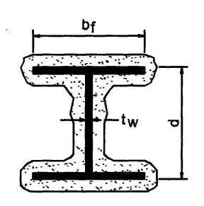
FIGURE 721.5.1(5)
WIDE FLANGE STRUCTURAL STEEL COLUMNS WITH SPRAYED FIRE-RESISTANT MATERIALS
721.5.1.3.1 Material-dependent constants. The material-dependent constants, C1 and C2, shall be determined for specific fire-resistant materials on the basis of standard fire endurance tests in accordance with Section 703.2. Unless evidence is submitted to the building official substantiating a broader application, this expression shall be limited to determining the fire resistance of structural steel columns with weight-to-heated-perimeter ratios (W/D) between the largest and smallest columns for which standard fire-resistance test results are available.
721.5.1.3.2 Identification. Sprayed fire-resistant materials shall be identified by density and thickness required for a given fire-resistance rating.
721.5.1.4 Concrete-protected columns. The fire resistance of structural steel columns protected with concrete, as illustrated in Figure 721.5.1(6) (a) and (b), shall be permitted to be determined from the following expression:

where:
R0 = 10 (W/D)0.7 + 17 (h1.6lkc0.2) × [1+26 {H/pccch(L+h)}0.8]
As used in these expressions:
R = Fire endurance at equilibrium moisture conditions (minutes).
R0 = Fire endurance at zero moisture content (minutes).
m = Equilibrium moisture content of the concrete by volume (percent).
W = Average weight of the steel column (pounds per linear foot).
D = Heated perimeter of the steel column (inches).
h = Thickness of the concrete cover (inches).
kc = Ambient temperature thermal conductivity of the concrete (Btu/hr ft °F).
H = Ambient temperature thermal capacity of the steel column = 0.11W (Btu/ ft °F).
pc = Concrete density (pounds per cubic foot).
cc = Ambient temperature specific heat of concrete (Btu/lb °F).
L = Interior dimension of one side of a square concrete box protection(inches).
721.5.1.4.1 Reentrant space filled. For wide-flange steel columns completely encased in concrete with all reentrant spaces filled [Figure 721.5.1(6)(c)], the thermal capacity of the concrete within the reentrant spaces shall be permitted to be added to the thermal capacity of the steel column, as follows:

where:
bf = Flange width of the steel column (inches).
238d = Depth of the steel column (inches).
As = Cross-sectional area of the steel column (square inches).
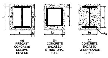
FIGURE 721.5.1(6)
CONCRETE PROTECTED STRUCTURAL STEEL COLUMNSa,b
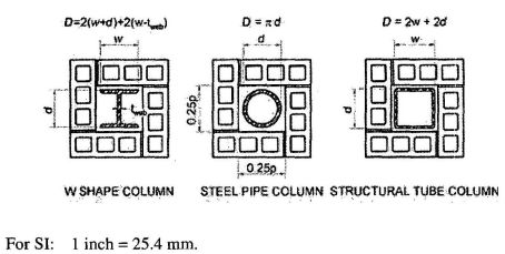
FIGURE 721.51(7)
CONCRETE OR CLAY MASONRY PROTECTED STRUCTURAL STEEL COLUMNS
For SI: 1 inch = 25.4 mm.
d = Depth of a wide flange column, outside diameter of pipe column, or outside dimension of structural tubing column (inches).
tweb = Thickness of web of wide flange column (inches).
w = Width of flange of wide flange column (inches).
721.5.1.4.2 Concrete properties unknown. If specific data on the properties of concrete are not available, the values given in Table 721.5.1(2) are permitted.
721.5.1.4.3 Minimum concrete cover. For structural steel column encased in concrete with all reentrant spaces filled, Figure 721.5.1(6)(c) and Tables 721.5.1(7) and 721.5.1(8) indicate the thickness of concrete cover required for various fire-resistance ratings for typical wide-flange sections. The thicknesses of concrete indicated in these tables also apply to structural steel columns larger than those listed.
721.5.1.4.4 Minimum precast concrete cover. For structural steel columns protected with precast concrete column covers as shown in Figure 721.5.1(6)(a), Tables 721.5.1(9) and 721.5.1(10) indicate the thickness of the column covers required for various fire-resistance ratings for typical wide-flange shapes. The thicknesses of concrete given in these tables also apply to structural steel columns larger than those listed.
721.5.1.4.5 Masonry protection. The fire resistance of structural steel columns protected with concrete masonry units or clay masonry units as illustrated in Figure 721.5.1(7), shall be permitted to be determined from the following expression:
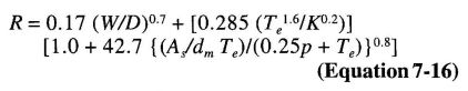
where:
R = Fire-resistance rating of column assembly (hours).
W = Average weight of steel column (pounds per foot).
D = Heated perimeter of steel column (inches) [see Figure 721.5.1(7)].
Te = Equivalent thickness of concrete or clay masonry unit (inches) (see Table 721.3.2 Note a or Section 721.4.1).
K = Thermal conductivity of concrete or clay masonry unit (Btu/hr. ft.°F) [see Table 721.5.1(3)].
As = Cross-sectional area of steel column (square inches).
dm = Density of the concrete or clay masonry unit (pounds per cubic foot).
p = Inner perimeter of concrete or clay masonry protection (inches) [see Figure 721.5.1(7)].
721.5.1.4.6 Equivalent concrete masonry thickness. For structural steel columns protected with concrete masonry, Table 721.5.1(5) gives the equivalent thickness of concrete masonry required for various fire-resistance ratings for typical column shapes. For structural steel columns protected with clay masonry, Table 721.5.1(6) gives the equivalent thickness of concrete masonry required for various fire-resistance ratings for typical column shapes.
721.5.2 Structural steel beams and girders. The fire-resistance ratings of steel beams and girders shall be based upon the size of the element and the type of protection provided in accordance with this section.
721.5.2.1 Determination of fire resistance. These procedures establish a basis for determining resistance of structural steel beams and girders which differ in size from that specified in approved fire-resistance-rated assemblies as a function of the thickness of fire-resistant material and the weight (W) and heated perimeter (D) of the beam or girder. As used in these sections, W is the average weight of a structural steel member in pounds per linear foot (plf). The heated perimeter, D, is the inside perimeter of the fire-resistant material in inches as illustrated in Figure 721.5.2.
| STRUCTURAL SHAPE | CONTOUR PROFILE | BOX PROFILE | STRUCTURAL SHAPE | CONTOUR PROFILE | BOX PROFILE |
|---|---|---|---|---|---|
| W14×233 | 2.49 | 3.65 | W10×112 | 1.78 | 2.57 |
| ×211 | 2.28 | 3.35 | ×100 | 1.61 | 2.33 |
| ×193 | 2.10 | 3.09 | ×88 | 1.43 | 2.08 |
| ×176 | 1.93 | 2.85 | ×77 | 1.26 | 1.85 |
| ×159 | 1.75 | 2.60 | ×68 | 1.13 | 1.66 |
| ×145 | 1.61 | 2.39 | ×60 | 1.00 | 1.48 |
| ×132 | 1.52 | 2.25 | ×54 | 0.91 | 1.34 |
| ×120 | 1.39 | 2.06 | ×49 | 0.83 | 1.23 |
| ×109 | 1.27 | 1.88 | ×45 | 0.87 | 1.24 |
| ×99 | 1.16 | 1.72 | ×39 | 0.76 | 1.09 |
| ×90 | 1.06 | 1.58 | ×33 | 0.65 | 0.93 |
| ×82 | 1.20 | 1.68 | |||
| ×74 | 1.09 | 1.53 | W8×67 | 1.34 | 1.94 |
| ×68 | 1.01 | 1.41 | ×58 | 1.18 | 1.71 |
| ×61 | 0.91 | 1.28 | ×48 | 0.99S | 1.44 |
| ×53 | 0.89 | 1.21 | ×40 | 0.83 | 1.23 |
| ×48 | 0.81 | 1.10 | ×35 | 0.73 | 1.08 |
| ×43 | 0.73 | 0.99 | ×31 | 0.65 | 0.97 |
| ×28 | 0.67 | 0.96 | |||
| W12×190 | 2.46 | 3.51 | ×24 | 0.58 | 0.83 |
| ×170 | 2.22 | 3.20 | ×21 | 0.57 | 0.77 |
| ×152 | 2.01 | 2.90 | ×18 | 0.49 | 0.67 |
| ×136 | 1.82 | 2.63 | |||
| ×120 | 1.62 | 2.36 | W6×25 | 0.69 | 1.00 |
| ×106 | 1.44 | 2.11 | ×20 | 0.56 | 0.82 |
| ×96 | 1.32 | 1.93 | ×16 | 0.57 | 0.78 |
| ×87 | 1.20 | 1.76 | ×15 | 0.42 | 0.63 |
| ×79 | 1.10 | 1.61 | ×12 | 0.43 | 0.60 |
| ×72 | 1.00 | 1.48 | ×9 | 0.33 | 0.46 |
| ×65 | 0.91 | 1.35 | |||
| ×58 | 0.91 | 1.31 | W5×19 | 0.64 | 0.93 |
| ×53 | 0.84 | 1.20 | ×16 | 0.54 | 0.80 |
| ×50 | 0.89 | 1.23 | |||
| ×45 | 0.81 | 1.12 | W4×13 | 0.54 | 0.79 |
| ×40 | 0.72 | 1.00 | |||
| For SI: 1 pound per linear foot per inch=0.059 kg/m/mm. | |||||
| PROPERTY | NORMAL-WEIGHT CONCRETE | STRUCTURAL LIGHTWEIGHT CONCRETE |
|---|---|---|
| Thermal conductivity (kc | 0.95 Btu/hr · ft · °F | 0.35 Btu/hr · ft · °F |
| Specific heat (Cc) | 0.20 Btu/1b °F | 0.20 Btu/1b °F |
| Density (Pc) | 145 lb/ft3 | 110 1b/ft3 |
| Equilibrium (free) moisture content (m) by volume | 4% | 5% |
| For SI: 1 inch = 25.4 mm, 1 foot = 304.8 mm, 1 1b/ft3 = 16.0185 kg/m3, Btu/hr · ft · °F = 1.731 W/(m · K). | ||
| DENSITY (dm) OF UNITS (Ib/ft3) | THERMAL CONDUCTIVITY (L) OF UNITS (Btu/hr · ft · °F) |
|---|---|
| Concrete Masonry Units | |
| 80 | 0.207 |
| 85 | 0.228 |
| 90 | 0.252 |
| 95 | 0.278 |
| 100 | 0.308 |
| 105 | 0.340 |
| 110 | 0.376 |
| 115 | 0.416 |
| 120 | 0.459 |
| 125 | 0.508 |
| 130 | 0.561 |
| 135 | 0.620 |
| 140 | 0.685 |
| 145 | 0.758 |
| 150 | 0.837 |
| Clay Masonry Units | |
| 120 | 1.25 |
| 130 | 2.25 |
| For SI: 1 pound per cubic foot = 16.0185 kg/m3, Btu/hr · ft · °F = 1.731 W/(m · K). | |
| STRUCTURAL SHAPE | CONTOUR PROFILE | BOX PROFILE | STRUCTURAL SHAPE | CONTOUR PROFILE | BOX PROFILE |
|---|---|---|---|---|---|
| W36 × 300 | 2.47 | 3.33 | W24 × 68 | 0.92 | 1.21 |
| ×280 | 2.31 | 3.12 | ×62 | 0.92 | 1.14 |
| ×260 | 2.16 | 2.92 | ×55 | 0.82 | 1.02 |
| ×245 | 2.04 | 2.76 | |||
| ×230 | 1.92 | 2.61 | W21 ×147 | 1.83 | 2.60 |
| ×210 | 1.94 | 2.45 | ×132 | 1.66 | 2.35 |
| ×194 | 1.80 | 2.28 | ×122 | 1.54 | 2.19 |
| ×182 | 1.69 | 2.15 | ×111 | 1.41 | 2.01 |
| ×170 | 1.59 | 2.01 | ×101 | 1.29 | 1.84 |
| ×160 | 1.50 | 1.90 | ×93 | 1.38 | 1.80 |
| ×150 | 1.41 | 1.79 | ×83 | 1.24 | 1.62 |
| ×135 | 1.28 | 1.63 | ×73 | 1.10 | 1.44 |
| ×68 | 1.03 | 1.35 | |||
| W33 ×241 | 2.11 | 2.86 | ×62 | 0.94 | 1.23 |
| ×221 | 1.94 | 2.64 | ×57 | 0.93 | 1.17 |
| ×201 | 1.78 | 2.42 | ×50 | 0.83 | 1.04 |
| ×152 | 1.51 | 1.94 | ×44 | 0.73 | 0.92 |
| ×141 | 1.41 | 1.80 | |||
| ×130 | 1.31 | 1.67 | W18×119 | 1.69 | 2.42 |
| ×118 | 1.19 | 1.53 | ×106 | 1.52 | 2.18 |
| ×97 | 1.39 | 2.01 | |||
| W30×211 | 2.00 | 2.74 | ×86 | 1.24 | 1.80 |
| ×191 | 1.82 | 2.50 | ×76 | 1.11 | 1.60 |
| ×173 | 1.66 | 2.28 | ×71 | 1.21 | 1.59 |
| ×132 | 1.45 | 1.85 | ×65 | 1.11 | 1.47 |
| ×124 | 1.37 | 1.75 | ×60 | 1.03 | 1.36 |
| ×116 | 1.28 | 1.65 | ×55 | 0.95 | 1.26 |
| ×108 | 1.20 | 1.54 | ×50 | 0.87 | 1.15 |
| ×99 | 1.10 | 1.42 | ×46 | 0.86 | 1.09 |
| ×40 | 0.75 | 0.96 | |||
| W27 ×178 | 1.85 | 2.55 | ×35 | 0.66 | 0.85 |
| ×161 | 1.68 | 2.33 | |||
| ×146 | 1.53 | 2.12 | W16 ×100 | 1.56 | 2.25 |
| ×114 | 1.36 | 1.76 | ×89 | 1.40 | 2.03 |
| ×102 | 1.23 | 1.59 | ×77 | 1.22 | 1.78 |
| ×94 | 1.13 | 1.47 | ×67 | 1.07 | 1.56 |
| ×84 | 1.02 | 1.33 | ×57 | 1.07 | 1.43 |
| ×50 | 0.94 | 1.26 | |||
| ×45 | 0.85 | 1.15 | |||
| W24 ×162 | 1.85 | 2.57 | ×40 | 0.76 | 1.03 |
| ×146 | 1.68 | 2.34 | ×36 | 0.69 | 0.93 |
| ×131 | 1.52 | 2.12 | ×31 | 0.65 | 0.83 |
| ×117 | 1.36 | 1.91 | ×26 | 0.55 | 0.70 |
| ×104 | 1.22 | 1.71 | |||
| ×94 | 1.26 | 1.63 | W14 ×132 | 1.83 | 3.00 |
| ×84 | 1.13 | 1.47 | ×120 | 1.67 | 2.75 |
| ×76 | 1.03 | 1.34 | ×109 | 1.53 | 2.52 |
| W14×99 | 1.39 | 2.31 | W10×30 | 0.79 | 1.12 |
| ×90 | 1.27 | 2.11 | ×26 | 0.69 | 0.98 |
| ×82 | 1.41 | 2.12 | ×22 | 0.59 | 0.84 |
| ×74 | 1.28 | 1.93 | ×19 | 0.59 | 0.78 |
| ×68 | 1.19 | 1.78 | ×17 | 0.54 | 0.70 |
| ×61 | 1.07 | 1.61 | ×15 | 0.48 | 0.63 |
| ×53 | 1.03 | 1.48 | ×12 | 0.38 | 0.51 |
| ×48 | 0.94 | 1.35 | |||
| ×43 | 0.85 | 1.22 | W8×67 | 1.61 | 2.55 |
| ×38 | 0.79 | 1.09 | ×58 | 1.41 | 2.26 |
| ×34 | 0.71 | 0.98 | ×48 | 1.18 | 1.91 |
| ×30 | 0.63 | 0.87 | ×40 | 1.00 | 1.63 |
| ×26 | 0.61 | 0.79 | ×35 | 0.88 | 1.44 |
| ×22 | 0.52 | 0.68 | ×31 | 0.79 | 1.29 |
| ×28 | 0.80 | 1.24 | |||
| W12×87 | 1.44 | 2.34 | ×24 | 0.69 | 1.07 |
| ×79 | 1.32 | 2.14 | ×21 | 0.66 | 0.96 |
| ×72 | 1.20 | 1.97 | ×18 | 0.57 | 0.84 |
| ×65 | 1.09 | 1.79 | ×15 | 0.54 | 0.74 |
| ×58 | 1.08 | 1.69 | ×13 | 0.47 | 0.65 |
| ×53 | 0.99 | 1.55 | ×10 | 0.37 | 0.51 |
| ×50 | 1.04 | 1.54 | |||
| ×45 | 0.95 | 1.40 | W6×25 | 0.82 | 1.33 |
| ×40 | 0.85 | 1.25 | ×20 | 0.67 | 1.09 |
| ×35 | 0.79 | 1.11 | ×16 | 0.66 | 0.96 |
| ×30 | 0.69 | 0.96 | ×15 | 0.51 | 0.83 |
| ×26 | 0.60 | 0.84 | ×12 | 0.51 | 0.75 |
| ×22 | 0.61 | 0.77 | ×9 | 0.39 | 0.57 |
| ×19 | 0.53 | 0.67 | |||
| ×16 | 0.45 | 0.57 | W5×19 | 0.76 | 1.24 |
| ×14 | 0.40 | 0.50 | ×16 | 0.65 | 1.07 |
| W10×112 | 2.14 | 3.38 | W4×13 | 0.65 | 1.05 |
| ×100 | 1.93 | 3.07 | |||
| ×88 | 1.70 | 2.75 | |||
| ×77 | 1.52 | 2.45 | |||
| ×68 | 1.35 | 2.20 | |||
| ×60 | 1.20 | 1.97 | |||
| ×54 | 1.09 | 1.79 | |||
| ×49 | 0.99 | 1.64 | |||
| ×45 | 1.03 | 1.59 | |||
| ×39 | 0.94 | 1.40 | |||
| ×33 | 0.77 | 1.20 | |||
| For SI:Pounds per linear foot per inch = 0.059 kg/m/mm. | |||||
| COLUMN SIZE | CONCRETE MASONRY DENSITY POUNDS PER CUBIC FOOT | MINIMUM REQUIRED EQUIVALENT THICKNESS FOR FIRE-RESISTANCE RATING OF CONCRETE MASONRY PROTECTION ASSEMBLY, Te (inches) | COLUMN SIZE | CONCRETE MASONRY DENSITY POUNDS PER CUBIC FOOT | MINIMUM REQUIRED EQUIVALENT THICKNESS FOR FIRE-RESISTANCE RATING OF CONCRETE MASONRY PROTECTION ASSEMBLY, Te (inches) | ||||||
|---|---|---|---|---|---|---|---|---|---|---|---|
| 1-hour | 2-hour | 3-hour | 4-hour | 1-hour | 2-hour | 3-hour | 4-hour | ||||
| W14 × 82 | 80 | 0.74 | 1.61 | 2.36 | 3.04 | W10 × 68 | 80 | 0.72 | 1.58 | 2.33 | 3.01 |
| 100 | 0.89 | 1.85 | 2.67 | 3.40 | 100 | 0.87 | 1.83 | 2.65 | 3.38 | ||
| 110 | 0.96 | 1.97 | 2.81 | 3.57 | 110 | 0.94 | 1.95 | 2.79 | 3.55 | ||
| 120 | 1.03 | 2.08 | 2.95 | 3.73 | 120 | 1.01 | 2.06 | 2.94 | 3.72 | ||
| W14 × 68 | 80 | 0.83 | 1.70 | 2.45 | 3.13 | W10 × 54 | 80 | 0.88 | 1.76 | 2.53 | 3.21 |
| 100 | 0.99 | 1.95 | 2.76 | 3.49 | 100 | 1.04 | 2.01 | 2.83 | 3.57 | ||
| 110 | 1.06 | 2.06 | 2.91 | 3.66 | 110 | 1.11 | 2.12 | 2.98 | 3.73 | ||
| 120 | 1.14 | 2.18 | 3.05 | 3.82 | 120 | 1.19 | 2.24 | 3.12 | 3.90 | ||
| W14×53 | 80 | 0.91 | 1.81 | 2.58 | 3.27 | W10 × 45 | 80 | 0.92 | 1.83 | 2.60 | 3.30 |
| 100 | 1.07 | 2.05 | 2.88 | 3.62 | 100 | 1.08 | 2.07 | 2.90 | 3.64 | ||
| 110 | 1.15 | 2.17 | 3.02 | 3.78 | 110 | 1.16 | 2.18 | 3.04 | 3.80 | ||
| 120 | 1.22 | 2.28 | 3.16 | 3.94 | 120 | 1.23 | 2.29 | 3.18 | 3.96 | ||
| W14×43 | 80 | 1.01 | 1.93 | 2.71 | 3.41 | W10 ×33 | 80 | 1.06 | 2.00 | 2.79 | 3.49 |
| 100 | 1.17 | 2.17 | 3.00 | 3.74 | 100 | 1.22 | 2.23 | 3.07 | 3.81 | ||
| 110 | 1.25 | 2.28 | 3.14 | 3.90 | 110 | 1.30 | 2.34 | 3.20 | 3.96 | ||
| 120 | 1.32 | 2.38 | 3.27 | 4.05 | 120 | 1.37 | 2.44 | 3.33 | 4.12 | ||
| W12 × 72 | 80 | 0.81 | 1.66 | 2.41 | 3.09 | W8 × 40 | 80 | 0.94 | 1.85 | 2.63 | 3.33 |
| 100 | 0.91 | 1.88 | 2.70 | 3.43 | 100 | 1.10 | 2.10 | 2.93 | 3.67 | ||
| 110 | 0.99 | 1.99 | 2.84 | 3.60 | 110 | 1.18 | 2.21 | 3.07 | 3.83 | ||
| 120 | 1.06 | 2.10 | 2.98 | 3.76 | 120 | 1.25 | 2.32 | 3.20 | 3.99 | ||
| W12 ×58 | 80 | 0.88 | 1.76 | 2.52 | 3.21 | W8 × 31 | 80 | 1.06 | 2.00 | 2.78 | 3.49 |
| 100 | 1.04 | 2.01 | 2.83 | 3.56 | 100 | 1.22 | 2.23 | 3.07 | 3.81 | ||
| 110 | 1.11 | 2.12 | 2.97 | 3.73 | 110 | 1.29 | 2.33 | 3.20 | 3.97 | ||
| 120 | 1.19 | 2.23 | 3.11 | 3.89 | 120 | 1.36 | 2.44 | 3.33 | 4.12 | ||
| W12 ×50 | 80 | 0.91 | 1.81 | 2.58 | 3.27 | W8 × 24 | 80 | 1.14 | 2.09 | 2.89 | 3.59 |
| 100 | 1.07 | 2.05 | 2.88 | 3.62 | 100 | 1.29 | 2.31 | 3.16 | 3.90 | ||
| 110 | 1.15 | 2.17 | 3.02 | 3.78 | 110 | 1.36 | 2.42 | 3.28 | 4.05 | ||
| 120 | 1.22 | 2.28 | 3.16 | 3.94 | 120 | 1.43 | 2.52 | 3.41 | 4.20 | ||
| W12 × 40 | 80 | 1.01 | 1.94 | 2.72 | 3.41 | W8 × 18 | 80 | 1.22 | 2.20 | 3.01 | 3.72 |
| 100 | 1.17 | 2.17 | 3.01 | 3.75 | 100 | 1.36 | 2.40 | 3.25 | 4.01 | ||
| 110 | 1.25 | 2.28 | 3.14 | 3.90 | 110 | 1.42 | 2.50 | 3.37 | 4.14 | ||
| 120 | 1.32 | 2.39 | 3.27 | 4.06 | 120 | 1.48 | 2.59 | 3.49 | 4.28 | ||
| 4X4X½ wall thickness | 80 | 0.93 | 1.90 | 2.71 | 3.43 | 4 double extra strong 0.674 wall thickness | 80 | 0.80 | 1.75 | 2.56 | 3.28 |
| 100 | 1.08 | 2.13 | 2.99 | 3.76 | 100 | 0.95 | 1.99 | 2.85 | 3.62 | ||
| 110 | 1.16 | 2.24 | 3.13 | 3.91 | 110 | 1.02 | 2.10 | 2.99 | 3.78 | ||
| 120 | 1.22 | 2.34 | 3.26 | 4.06 | 120 | 1.09 | 2.20 | 3.12 | 3.93 | ||
| 4x4x3/8 wall thickness | 80 | 1.05 | 2.03 | 2.84 | 4.06 | 4 extra strong 0.337 wall thickness | 80 | 1.12 | 2.11 | 2.93 | 3.65 |
| 100 | 1.20 | 2.25 | 3.11 | 3.88 | 100 | 1.26 | 2.32 | 3.19 | 3.95 | ||
| 110 | 1.27 | 2.35 | 3.24 | 4.02 | 110 | 1.33 | 2.42 | 3.31 | 4.09 | ||
| 120 | 1.34 | 2.45 | 3.37 | 4.17 | 120 | 1.40 | 2.52 | 3.43 | 4.23 | ||
| 4x4x¼ wall thickness | 80 | 1.21 | 2.20 | 3.01 | 3.73 | 4 standard 0.237 wall thickness | 80 | 1.26 | 2.25 | 3.07 | 3.79 |
| 100 | 1.35 | 2.40 | 3.26 | 4.02 | 100 | 1.40 | 2.45 | 3.31 | 4.07 | ||
| 110 | 1.41 | 2.50 | 3.38 | 4.16 | 110 | 1.46 | 2.55 | 3.43 | 4.21 | ||
| 120 | 1.48 | 2.59 | 3.50 | 4.30 | 120 | 1.53 | 2.64 | 3.54 | 4.34 | ||
| 6x6X½wall thickness | 80 | 0.82 | 1.75 | 2.54 | 3.25 | 5 double extra strong 0.750 wall thickness | 80 | 0.70 | 1.61 | 2.40 | 3.12 |
| 100 | 0.98 | 1.99 | 2.84 | 3.59 | 100 | 0.85 | 1.86 | 2.71 | 3.47 | ||
| 110 | 1.05 | 2.10 | 2.98 | 3.75 | 110 | 0.91 | 1.97 | 2.85 | 3.63 | ||
| 120 | 1.12 | 2.21 | 3.11 | 3.91 | 120 | 0.98 | 2.02 | 2.99 | 3.79 | ||
| 6x6x3/8 wall thickness | 80 | 0.96 | 1.91 | 2.71 | 3.42 | 5 extra strong 0.375 wall thickness | 80 | 1.04 | 2.01 | 2.83 | 3.54 |
| 100 | 1.12 | 2.14 | 3.00 | 3.75 | 100 | 1.19 | 2.23 | 3.09 | 3.85 | ||
| 110 | 1.19 | 2.25 | 3.13 | 3.90 | 110 | 1.26 | 2.34 | 3.22 | 4.00 | ||
| 120 | 1.26 | 2.35 | 3.26 | 4.05 | 120 | 1.32 | 2.44 | 3.34 | 4.14 | ||
| 6x6x¼ | 80 | 1.14 | 2.11 | 2.92 | 3.63 | 5 standard 0.258 wall thickness | 80 | 1.20 | 2.19 | 3.00 | 3.72 |
| 100 | 1.29 | 2.32 | 3.18 | 3.93 | 100 | 1.34 | 2.39 | 3.25 | 4.00 | ||
| 110 | 1.36 | 2.43 | 3.30 | 4.08 | 110 | 1.41 | 2.49 | 3.37 | 4.14 | ||
| 120 | 1.42 | 2.52 | 3.43 | 4.22 | 120 | 1.47 | 2.58 | 3.49 | 4.28 | ||
| 8x8x½ wall thickness | 80 | 0.77 | 1.66 | 2.44 | 3.13 | 6 double extra strong 0.864 wall thickness | 80 | 0.59 | 1.46 | 2.23 | 2.92 |
| 100 | 0.92 | 1.91 | 2.75 | 3.49 | 100 | 0.73 | 1.71 | 2.54 | 3.29 | ||
| 110 | 1.00 | 2.02 | 2.89 | 3.66 | 110 | 0.80 | 1.82 | 2.69 | 3.47 | ||
| 120 | 1.07 | 2.14 | 3.03 | 3.82 | 120 | 0.86 | 1.93 | 2.83 | 3.63 | ||
| 8x8x3/8 wall thickness | 80 | 0.91 | 1.84 | 2.63 | 3.33 | 6 extra strong 0.432 wall thickness | 80 | 0.94 | 1.90 | 2.70 | 3.42 |
| 100 | 1.07 | 2.08 | 2.92 | 3.67 | 100 | 1.10 | 2.13 | 2.98 | 3.74 | ||
| 110 | 1.14 | 2.19 | 3.06 | 3.83 | 110 | 1.17 | 2.23 | 3.11 | 3.89 | ||
| 120 | 1.21 | 2.29 | 3.03 | 3.82 | 120 | 1.24 | 2.34 | 3.24 | 4.04 | ||
| 8x8x3/8 wall thickness | 80 | 0.91 | 1.84 | 2.63 | 3.33 | 6 extra strong thickness | 80 | 0.94 | 1.90 | 2.70 | 3.42 |
| 100 | 1.07 | 2.08 | 2.92 | 3.67 | 100 | 1.10 | 2.13 | 2.98 | 3.74 | ||
| 110 | 1.14 | 2.19 | 3.06 | 3.83 | 110 | 1.17 | 2.23 | 3.11 | 3.89 | ||
| 120 | 1.21 | 2.29 | 3.19 | 3.98 | 120 | 1.24 | 2.34 | 3.24 | 4.04 | ||
| 8x8x¼ wall thickness | 80 | 1.10 | 2.06 | 2.86 | 3.57 | 6 standard 0.280 wall thickness | 80 | 1.14 | 2.12 | 2.93 | 3.64 |
| 100 | 1.25 | 2.28 | 3.13 | 3.87 | 100 | 1.29 | 2.33 | 3.19 | 3.94 | ||
| 110 | 1.32 | 2.38 | 3.25 | 4.02 | 110 | 1.36 | 2.43 | 3.31 | 4.08 | ||
| 120 | 1.39 | 2.48 | 3.38 | 4.17 | 120 | 1.42 | 2.53 | 3.43 | 4.22 | ||
| For SI: 1 inch = 25.4 mm, 1 pound per cubic feet = 16.02 kg/m3. | |||||||||||
| Note: Tabulated values assume 1-inch air gap between masonry and steel section. | |||||||||||
| COLUMN SIZE | CLAY MASONRY DENSITY, POUNDS PER CUBIC FOOT | MINIMUM REQUIRED EQUIVALENT THICKNESS FOR FIRE-RESISTANCE RATING OF CLAY MASONRY PROTECTION ASSEMBLY, Te(inches) | COLUMN SIZE | CLAY MASONRY DENSITY, POUNDS PER CUBIC FOOT | MINIMUM REQUIRED EQUIVALENT THICKNESS FOR FIRE-RESISTANCE RATING OF CLAY MASONRY PROTECTION ASSEMBLY, Te(inches) | ||||||
|---|---|---|---|---|---|---|---|---|---|---|---|
| 1-hour | 2-hour | 3-hour | 4-hour | 1-hour | 2-hour | 3-hour | 4-hour | ||||
| W14 × 82 | 120 | 1.23 | 2.42 | 3.41 | 4.29 | W10 × 68 | 120 | 1.27 | 2.46 | 3.26 | 4.35 |
| 130 | 1.40 | 2.70 | 3.78 | 4.74 | 1.44 | 2.75 | 3.83 | 4.80 | |||
| W14 × 68 | 120 | 1.34 | 2.54 | 3.54 | 4.43 | W10 × 54 | 120 | 1.40 | 2.61 | 3.62 | 4.51 |
| 130 | 1.51 | 2.82 | 3.91 | 4.87 | 130 | 1.58 | 2.89 | 3.98 | 4.95 | ||
| W14 × 53 | 120 | 1.43 | 2.65 | 3.65 | 4.54 | W10 × 45 | 120 | 1.44 | 2.66 | 3.67 | 4.57 |
| 130 | 1.61 | 2.93 | 4.02 | 4.98 | 130 | 1.62 | 2.95 | 4.04 | 5.01 | ||
| W14 × 43 | 120 | 1.54 | 2.76 | 3.77 | 4.66 | W10 × 33 | 120 | 1.59 | 2.82 | 3.84 | 4.73 |
| 130 | 1.72 | 3.04 | 4.13 | 5.09 | 130 | 1.77 | 3.10 | 4.20 | 5.13 | ||
| W12 × 72 | 120 | 1.32 | 2.52 | 3.51 | 4.40 | W8 × 40 | 120 | 1.47 | 2.70 | 3.71 | 4.61 |
| 130 | 1.50 | 2.80 | 3.88 | 4.84 | 130 | 1.65 | 2.98 | 4.08 | 5.04 | ||
| W12 × 58 | 120 | 1.40 | 2.61 | 3.61 | 4.50 | W8 × 31 | 120 | 1.59 | 2.82 | 3.84 | 4.73 |
| 130 | 1.57 | 2.89 | 3.98 | 4.94 | 130 | 1.77 | 3.10 | 4.20 | 5.17 | ||
| W12 × 50 | 120 | 1.43 | 2.65 | 3.66 | 4.55 | W8 × 24 | 120 | 1.66 | 2.90 | 3.92 | 4.82 |
| 130 | 1.61 | 2.93 | 4.02 | 4.99 | 130 | 1.84 | 3.18 | 4.28 | 5.25 | ||
| W12 × 40 | 120 | 1.54 | 2.77 | 3.78 | 4.67 | W8 × 18 | 120 | 1.75 | 3.00 | 4.01 | 4.91 |
| 130 | 1.72 | 3.05 | 4.14 | 5.10 | 130 | 1.93 | 3.27 | 4.37 | 5.34 | ||
| STEEL TUBING | STEEL PIPE | ||||||||||
| NOMINAL TUBE SIZE (inches) | CLAY MASONRY DENSITY, POUNDS PER CUBIC FOOT | MINIMUM REQUIRED EQUIVALENT THICKNESS FOR FIRE-RESISTANCE RATING OF CLAY MASONRY PROTECTION ASSEMBLY, Te(inches) | NOMINAL PIPE SIZE (inches) | CLAY MASONRY DENSITY, POUNDS PER CUBIT FOOT | MINIMUM REQUIRED EQUIVALENT THICKNESS FOR FIRE-RESISTANCE RATING OF CLAY MASONRY PROTECTION ASSEMBLY, Te(inches) | ||||||
| 1-hour | 2-hour | 3-hour | 4-hour | 1-hour | 2-hour | 3-hour | 4-hour | ||||
| 4 × 4 × ½ wall thickness | 120 | 1.44 | 2.72 | 3.76 | 4.68 | 4 double extra strong 0.674 wall thickness | 120 | 1.26 | 2.55 | 3.60 | 4.52 |
| 130 | 1.62 | 3.00 | 4.12 | 5.11 | 130 | 1.42 | 2.82 | 3.96 | 4.95 | ||
| 4 × 4 × 3/8 wall thickness | 120 | 1.56 | 2.84 | 3.88 | 4.78 | 4 extra strong 0.337 wall thickness | 120 | 1.60 | 2.89 | 3.92 | 4.83 |
| 130 | 1.74 | 3.12 | 4.23 | 5.21 | 130 | 1.77 | 3.16 | 4.28 | 5.25 | ||
| 4 × 4 × ¼ wall thickness | 120 | 1.72 | 2.99 | 4.02 | 4.92 | 4 standard 0.237 wall thickness | 120 | 1.74 | 3.02 | 4.05 | 4.95 |
| 130 | 1.89 | 3.26 | 4.37 | 5.34 | 130 | 1.92 | 3.29 | 4.40 | 5.37 | ||
| 6 × 6 × ½ wall thickness | 120 | 1.33 | 2.58 | 3.62 | 4.52 | 5 double extra strong 0.750 wall thickness | 120 | 1.17 | 2.44 | 3.48 | 4.40 |
| 130 | 1.50 | 2.86 | 3.98 | 4.96 | 130 | 1.33 | 2.72 | 3.84 | 4.83 | ||
| 6 × 6 × 3/8 wall thickness | 120 | 1.48 | 2.74 | 3.76 | 4.67 | 5 extra strong 0.375 wall thickness | 120 | 1.55 | 2.82 | 3.85 | 4.76 |
| 130 | 1.65 | 3.01 | 4.13 | 5.10 | 130 | 1.72 | 3.09 | 4.21 | 5.18 | ||
| 6 × 6 × ¼ wall thickness | 120 | 1.66 | 2.91 | 3.94 | 4.84 | 5 standard 0.258 wall thickness | 120 | 1.71 | 2.97 | 4.00 | 4.90 |
| 130 | 1.83 | 3.19 | 4.30 | 5.27 | 130 | 1.88 | 3.24 | 4.35 | 5.32 | ||
| 8 × 8 × ½ wall thickness | 120 | 1.27 | 2.50 | 3.52 | 4.42 | 6 double extra strong 0.864 wall thickness | 120 | 1.04 | 2.28 | 3.32 | 4.23 |
| 130 | 1.44 | 2.78 | 3.89 | 4.86 | 130 | 1.19 | 2.60 | 3.68 | 4.67 | ||
| 8 × 8 × 3/8 wall thickness | 120 | 1.43 | 2.67 | 3.69 | 4.59 | 6 extra strong 0.432 wall thickness | 120 | 1.45 | 2.71 | 3.75 | 4.65 |
| 130 | 1.60 | 2.95 | 4.05 | 5.02 | 130 | 1.62 | 2.91 | 3.94 | 4.84 | ||
| 8 × 8 × ¼ wall thickness | 120 | 1.62 | 2.87 | 3.89 | 4.78 | 6 standard 0.280 wall thickness | 120 | 1.65 | 2.91 | 3.94 | 4.84 |
| 130 | 1.79 | 3.14 | 4.24 | 5.21 | 130 | 1.82 | 3.19 | 4.30 | 5.27 | ||
| STRUCTURAL SHAPE | FIRE-RESISTANCE RATING (hours) | ||||
|---|---|---|---|---|---|
| 1 | 1½ | 2 | 3 | 4 | |
| W14 × 233 | 1 | 1 | 1 | 1½ | 2 |
| × 176 | 2½ | ||||
| × 132 | 2 | ||||
| × 90 | 2½ | ||||
| × 61 | 3 | ||||
| × 48 | 1½ | 2½ | |||
| × 43 | |||||
| W12 × 152 | 1 | 1 | 1 | 2 | 2½ |
| × 96 | |||||
| × 65 | 1½ | 1½ | 3 | ||
| × 50 | 2½ | ||||
| × 40 | |||||
| W10 × 88 | 1 | 1½ | 1½ | 2 | 3 |
| × 49 | 1 | 2½ | |||
| × 45 | |||||
| × 39 | 3½ | ||||
| × 33 | 2 | ||||
| W8 × 67 | 1 | 1 | 1½ | 2½ | 3 |
| × 58 | |||||
| × 48 | 1½ | 3½ | |||
| × 31 | 2 | 3 | |||
| × 21 | |||||
| × 18 | 4 | ||||
| W6 × 25 | 1 | 1½ | 2 | 3 3½ | 3½ |
| × 20 | 2 | 2½ | 4 | ||
| × 16 | |||||
| × 15 | 1½ | ||||
| × 9 | |||||
| For SI: 1 inch = 25.4 mm. | |||||
| a. The tabulated thicknesses are based upon the assumed propertics of normal-weight concrete given in Table 721.5.1(2). | |||||
| STRUCTURAL SHAPE | FIRE-RESISTANCE RATING (HOURS) | ||||
|---|---|---|---|---|---|
| 1 | 1½ | 2 | 3 | 4 | |
| W14 × 233 | 1 | 1 | 1 | 1 | 1½ |
| × 193 | 1½ | ||||
| × 74 | 2 | ||||
| × 61 | 2½ | ||||
| × 43 | 1½ | 2 | |||
| W12 × 65 | 1 | 1 | 1 | 1½ | 2 |
| × 53 | 2 | 2½ | |||
| × 40 | 1½ | ||||
| W10 × 112 | 1 | 1 | 1 | 1½ | 2 |
| × 88 | |||||
| × 60 | 2 | 2½ | |||
| × 33 | 1½ | ||||
| W8 × 35 | 1 | 1 | 1½ | 2 | 2½ |
| × 28 | 3 | ||||
| × 24 | 2½ | ||||
| × 18 | 1½ | ||||
| For SI: 1 inch = 25.4 mm. | |||||
| a. The tabulated thicknesses are based upon the assumed properties of structural lightweight concrete given in Table 721.5.1(2). | |||||
| STRUCTURAL SHAPE | FIRE-RESISTANCE RATING (hours) | ||||
|---|---|---|---|---|---|
| 1 | 1½ | 2 | 3 | 4 | |
| W14 × 233 | 1½ | 1½ | 1½ | 2½ | 3 |
| × 211 | 3½ | ||||
| × 176 | 2 | ||||
| × 145 | 3 | ||||
| × 109 | 2 | 2½ | |||
| × 99 | 4 | ||||
| × 61 | 3½ | ||||
| × 43 | 4½ | ||||
| W12 × 190 | 1½ | 1½ | 1½ | 2½ | 3½ |
| × 152 | 2 | ||||
| × 120 | 3 | 4 | |||
| × 96 | |||||
| × 87 | 2 | 2½ | 3½ | ||
| × 58 | 4½ | ||||
| × 40 | |||||
| W10 × 112 | 1½ | 1½ | 2 | 3 | 3½ |
| × 88 | 4 | ||||
| × 77 | 2 | 2½ | |||
| × 54 | 3½ | ||||
| × 33 | 4½ | ||||
| W8 × 67 | 1½ | 1½ | 2 | 3 | 4 |
| × 58 | 2 | 2½ | 3½ | ||
| × 48 | |||||
| × 28 | 4½ | ||||
| × 21 | 2½ | 3 | |||
| × 18 | 4 | ||||
| W6 × 25 | 1½ | 2 | 2½ | 3½ | 4½ |
| × 20 | 2½ | 3 | |||
| × 16 | 4 | ||||
| × 12 | 2 | ||||
| × 9 | 5 | ||||
| For SI: 1 inch = 25.4 mm. | |||||
| a. The tabulated thicknesses are based upon the assumed properties of normal-weight concrete given in Table 721.5.1(2). | |||||
| STRUCTURAL SHAPE | FIRE-RESISTANCE RATING (hours) | ||||
|---|---|---|---|---|---|
| 1 | 1½ | 2 | 3 | 4 | |
| W14 × 233 | 1½ | 1½ | 1½ | 2 | 2½ |
| × 176 | 3 | ||||
| × 145 | 2½ | ||||
| × 132 | |||||
| × 109 | |||||
| × 99 | 2 | ||||
| × 68 | 3½ | ||||
| × 43 | 3 | ||||
| W12 × 190 | 1½ | 1½ | 1½ | 2 | 2½ |
| × 152 | |||||
| × 136 | 3 | ||||
| × 106 | 2½ | ||||
| × 96 | 3½ | ||||
| × 87 | |||||
| × 65 | 2 | ||||
| × 40 | 3 | ||||
| W10 × 112 | 1½ | 1½ | 1½ | 2 | 3 |
| × 100 | 2½ | ||||
| × 88 | |||||
| × 77 | 2 | 3½ | |||
| × 60 | |||||
| × 39 | 3 | ||||
| × 33 | 2 | ||||
| W8 × 67 | 1½ | 1½ | 1½ | 2½ | 3 |
| × 48 | 2 | 3 | 3½ | ||
| × 35 | |||||
| × 28 | 2 | ||||
| × 18 | 2½ | 4 | |||
| W6 × 25 | 1½ | 2 | 2 | 3 | 3½ |
| × 15 | 2½ | 4 | |||
| × 9 | 3½ | ||||
| For SI: 1 inch = 25.4 mm. | |||||
| a. The tabulated thicknesses are based upon the assumed properties of structural lightweight concrete given in Table 721.5.1(2). | |||||
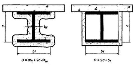
FIGURE 721.5.2 DETERMINATION OF THE HEATED PERIMETER OF STRUCTURAL STEEL BEAMS AND GIRDERS
721.5.2.1.1 Weight-to-heated perimeter. The weight-to-heated-perimeter ratios (W/D), for both contour and box fire-resistant protection profiles, for the wide flange shapes most often used as beams or girders are given in Table 721.5.1(4). For different shapes, the weight-to-heated-perimeter ratios (W/D) shall be determined in accordance with the definitions given in this section.
721.5.2.1.2 Beam and girder substitutions. Except as provided for in Section 721.5.2.2, structural steel beams in approved fire-resistance-rated assmblies shall be considered the minimum permissible size. Other beam or girder shaps shall be permitted to be substituted provided that the weight-to-heated-perimeter ratio (W/D) of the substitute beam is equal to or greater than that of the beam specified in the approved assembly.
721.5.2.2 Sprayed fire-resistant materials. The provisions in this section apply to structural steel beams and girders protected with sprayed fire-resistant materials. Larger or smaller beam and girder shapes shall be permitted to be substituted for beams specified in approved unrestrained or restrained fire-resistance-rated assemblies, provided that the thickness of the fire-resistant material is adjusted in accordance with the following expression:
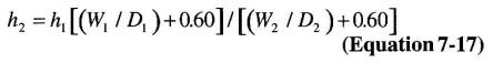
(Equation 7-17)
where:
h = Thickness of sprayed fire-resistant material in inches.
W = Weight of the structural steel beam or girder in pounds per linear foot.
D = Heated perimeter of the structural steel beam in inches.
Subscript 1 refers to the beam and fire-resistant material thickness in the approved assembly.
Subscript 2 refers to the substitute beam or girder and the required thickness of fire-resistant material.
The fire resistance of structural steel beams and girders protected with intumescent or mastic fire-resistant coatings shall be determined on the basis of fire-resistance tests in accordance with Section 703.2.
721.5.2.2.1 Minimum thickness. The use of Equation 7-17 is subject to the following conditions:
721.5.2.3 Structural steel trusses. The fire resistance of structural steel trusses protected with fire-resistant materials sprayed to each of the individual truss elements shall be permitted to be determined in accordance with this section. The thickness of the fire-resistant material shall be determined in accordance with Section 721.5.1.3. The weight-to-heated-perimeter ratio (W/D) of truss elements that can be simultaneously exposed to fire on all sides shall be determined on the same basis as columns, as specified in Section 721.5.1.1. The weight-to-heated-perimeter ratio (W/D) of truss elements that directly support floor or roof assembly shall be determined on the same basis as beams and girders, as specified in Section 721.5.2.1.
The fire resistance of structural steel trusses protected with intumescent or mastic fire-resistant coatings shall be determined on the basis of fire-resistance tests in accordance with Section 703.2.
721.6 Wood assemblies. The provisions of this section contain procedures by which the fire-resistance ratings of wood assemblies are established by calculations.
721.6.1 General. This section contains procedures for calculating the fire-resistance ratings of walls, floor/ceiling and roof/ceiling assemblies based in part on the standard method of testing referenced in Section 703.2.
721.6.1.1 Maximum fire-resistance rating. Fire resistance ratings calculated for assemblies using the methods in Section 721.6 shall be limited to a maximum of 1 hour.
721.6.1.2 Dissimilar membranes. Where dissimilar membranes are used on a wall assembly, the calculation shall be made from the least fire-resistant (weaker) side.
721.6.2 Walls, floors and roofs. These procedures apply to both load-bearing and nonload-bearing assemblies.
721.6.2.1 Fire-resistance rating of wood frame assemblies. The fire-resistance rating of a wood frame assembly is equal to the sum of the time assigned to the membrane on the fire-exposed side, the time assigned to
249the framing members and the time assigned for additional contribution by other protective measures such as insulation. The membrane on the unexposed side shall not be included in determining the fire resistance of the assembly.
721.6.2.2 Time assigned to membranes. Table 721.6.2(1) indicates the time assigned to membranes on the fire-exposed side.
721.6.2.3 Exterior walls. For an exterior wall with a fire separation distance greater than 5 feet (1524 mm), the wall is assigned a rating dependent on the interior membrane and the framing as described in Tables 721.6.2(1) and 721.6.2(2). The membrane on the outside of the nonfire-exposed side of exterior walls with a fire separation distance greater than 5 feet (1524 mm) may consist of sheathing, sheathing paper and siding as described in Table 721.6.2(3).
721.6.2.4 Floors and roofs. In the case of a floor or roof, the standard test provides only for testing for fire exposure from below. Except as noted in Section 703.3, Item 5, floor or roof assemblies of wood framing shall have an upper membrane consisting of a subfloor and finished floor conforming to Table 721.6.2(4) or any other membrane that has a contribution to fire resistance of at least 15 minutes in Table 721.6.2(1).
721.6.2.5 Additional protection. Table 721.6.2(5) indicates the time increments to be added to the fire resistance where glass fiber, rockwool, slag mineral wool or cellulose insulation is incorporated in the assembly.
721.6.2.6 Fastening. Fastening of wood frame assemblies and the fastening of membranes to the wood framing members shall be done in accordance with Chapter 23.
721.6.3 Design of fire-resistant exposed wood members. The fire-resistance rating, in minutes, of timber beams and columns with a maximum nominal dimension of 6 inches (152 mm) is equal to:
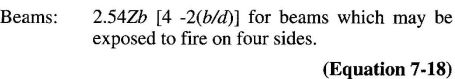
(Equation 7-18)
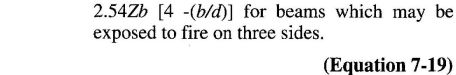
(Equation 7-19)
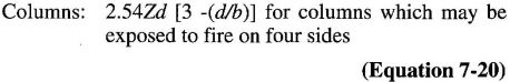
(Equation 7-20)
(Equation 7-21)
where:
b = The breadth (width) of a beam or larger side of a column before exposure to fire (inches).
d = The depth of a beam or smaller side of a column before exposure to fire (inches).
Z = Load factor, based on Figure 721.6.3(1).
| DESCRIPTION OF FINISH | TIMEe (minutes) |
|---|---|
| 3/8-inch wood structural panel bonded with exterior glue | 5 |
| 15/32-inch wood structural panel bonded with exterior glue | 10 |
| 19/32-inch wood structural panel bonded with exterior glue | 15 |
| 3/8-inch gypsum wallboard | 10 |
| ½-inch gypsum wallboard | 15 |
| 5/8-inch gypsum wallboard | 30 |
| ½-inch Type X gypsum wallboard | 25 |
| 5/8-inch Type X gypsum wallboard | 40 |
| Double 3/8-inch gypsum wallboard | 25 |
| ½-inch + 3/8-inch gypsum wallboard | 35 |
| Double ½-inch gypsum wallboard | 40 |
| For SI: 1 inch = 25.4 mm. | |
| a. These values apply only when membranes are installed on framing members which are spaced 16 inches o.c. | |
| b. Gypsum wallboard installed over framing or furring shall be installed so that all edges are supported, except 5/8-inch Type X gypsum wallboard shall be permitted to be installed horizontally with the horizontal joints staggered 24 inches each side and unsupported but finished. | |
| c. On wood frame floor/ceiling or roof/ceiling assemblies, gypsum board shall be installed with the long dimension perpendicular to framing members and shall have all joints finished. | |
| d. The membrane on the unexposed side shall not be included in determining the fire resistance of the assembly. When dissimilar membranes are used on a wall assembly, the calculation shall be made from the least fire-resistant (weaker) side. | |
| e. The time assigned is not a finished rating. | |
721.6.3.1 Equation 7-21. Equation 7-21 applies only where the unexposed face represents the smaller side of the column. If a column is recessed into a wall, its full dimension shall be used for the purpose of these calculations.
721.6.3.2 Allowable loads. Allowable loads on beams and columns are determined using design values given in AF&PA NDS.
721.6.3.3 Fastener protection. Where minimum 1-hour fire resistance is required, connectors and fasteners shall be protected from fire exposure by 1½ inches (38 mm) of wood, or other approved covering or coating for a 1-hour rating. Typical details for commonly used fasteners and connectors are shown in AITC Technical Note 7.
721.6.3.4 Minimum size. Wood members are limited to dimensions of 6 inches (152 mm) nominal or greater. Glued-laminated timber beams utilize standard laminating combinations except that a core lamination is removed. The tension zone is moved inward and the equivalent of an extra nominal 2-inch-thick (51 mm) outer tension lamination is added.
| DESCRIPTION | TIME ASSIGNED TO FRAME (minutes) |
|---|---|
| Wood studs 16 inches o.c. | 20 |
| Wood floor and roof joists 16 inches o.c. | 10 |
| For SI: 1 inch = 25.4 mm. | |
| This table does not apply to studs or joists spaced more than 16 inches o.c. | |
| All studs shall be nominal 2 × 4 and all joists shall have a nominal thickness of at least 2 inches. | |
| Allowable spans for joists shall be determined in accordance with Sections 2308.8, 2308.10.2 and 2308.10.3. | |
| SHEATHING | PAPER | EXTERIOR FINISH |
|---|---|---|
| 5/8-inch T & G lumber | Lumber siding | |
| 5/16-inch exterior glue wood structural panel | Sheathing paper | Wood shingles and shakes |
| ½-inch gypsum wallboard | ¼-inch wood structural panels—exterior type | |
| 5/8-inch gypsum wallboard | ¼-inch hardboard | |
| ½-inch fiberboard | Metal siding | |
| Stucco on metal lath | ||
| Masonry vencer | ||
| Vinyl siding | ||
| None | – | 3/8-inch exterior-grade wood structural panels |
| For SI: 1 pound/cubic foot = 16.0185 kg/m2. | ||
| a. Any combination of sheathing, paper and exterior finish is permitted. | ||
| ASSEMBLY | STRUCTURAL MEMBERS | SUBFLOOR OR ROOF DECK | FINISHED FLOORING OR ROOFING |
|---|---|---|---|
| Floor | Wood | 15/32-inch wood structural panels or 11/16 inch T & G softwood | Hardwood or softwood flooring on building paper resilient flooring, parquet floor felted-synthetic fiber floor coverings, carpeting, or ceramic tile on 3/8-inch-thick panel-type underlay Ceramic tile on 1¼-inch mortar bed |
| Roof | Wood | 15/32-inch wood structural panels or 11/16 inch T & G softwood | Finished roofing material with or without insulation |
| For SI: 1 inch = 25.4 mm. | |||
| a. This table applies only to wood joist construction. It is not applicable to wood truss construction. | |||
| DESCRIPTION OF ADDITIONAL PROTECTION | FIRE RESISTANCE (minutes) |
|---|---|
| Add to the fire-resistance rating of wood stud walls if the spaces between the studs are completely filled with glass fiber mineral wool batts weighing not less than 2 pounds per cubic foot (0.6 pound per square foot of wall surface) or rockwool or slag material wool batts weighing not less than 3.3 pounds per cubic foot (1 pound per square foot of wall surface), or cellulose insulation having a nominal density not less than 2.6 pounds per cubic foot. | 15 |
| For SI: 1 pound/cubic foot = 16.0185 kg/m3. | |
| Adopting agency | BSC | SFM | HCD | DSA | OSHPD | CSA | DPH | AGR | DWR | CEC | CA | SL | SLC | |||||||
|---|---|---|---|---|---|---|---|---|---|---|---|---|---|---|---|---|---|---|---|---|
| 1 | 2 | 1-AC | AC | SS | SS/CC | 1 | 2 | 3 | 4 | |||||||||||
| Adopt entire chapter | X | X | X | |||||||||||||||||
| Adopt entire chapter as amended (amended sections listed below) | ||||||||||||||||||||
| Adopt only those sections that are listed below | ||||||||||||||||||||
| Chapter/Section | ||||||||||||||||||||
| The Office of the State Fire Marshal's adoption of this chapter or individual sections is applicable to structures regulated by other state agencies pursuant to Section 1.11. | ||||||||||||||||||||
701A.1 Scope This chapter applies to building materials, systems and/or assemblies used in the exterior design and construction of new buildings located with in a Wildland-Urban Interface Fire Area as defined in Section 702A.
701A.2 Purpose. The purpose of this chapter is to establish minimum standards for the protection of life and property by increasing the ability of a building located in any Fire Hazard Severity Zone within State Responsibility Areas or any Wildland-Urban Interface Fire Area to resist the intrusion of flames or burning embers projected by a vegetation fire and contributes to a systematic reduction in conflagration losses.
701A.3 Application. New buildings located in any Fire Hazard Severity Zone or any Wildland-Urban Interface Fire Area designated by the enforcing agency constructed after the application date shall comply with the provisions of this chapter.
Exceptions:
- Buildings of an accessory character classified as a Group U occupancy and not exceeding 120 square feet in floor area, when located at least 30 feet from an applicable building.
- Buildings of an accessory character classified as Group U occupancy of any size located least 50 feet from an applicable building.
- Buildings classified as a Group U Agricultural Building, as defined in Section 202 of this code (see also Appendix C - Group U Agricultural Buildings), when located at least 50 feet from an applicable building.
- Additions to and remodels of buildings originally constructed prior to the applicable application date.
701A.3.1 Application date and where required. New buildings for which an application for a building permit is submitted on or after July 1, 2008 located in any Fire Hazard Severity Zone or Wildland Interface Fire Area shall comply with all sections of this chapter, including all of the following areas:
Exceptions:
- New buildings located in any Fire Hazard Severity Zone within State Responsibility Areas, for which an application for a building permit is submitted on or after January 1, 2008, shall comply with all sections of this chapter.
- New buildings located in any Fire Hazard Severity Zone within State Responsibility Areas or any Wildland Interface Fire Area designated by cities and other local agencies for which an application for a building permit is submitted on or after December 1, 2005 but prior to July 1, 2008, shall only comply with the following sections of this chapter:
- Section 705A–Roofing
- Section 706A–Attic Ventilation
701A.4 Inspection and certification. Building permit applications and final completion approvals for buildings within the scope and application of this chapter shall comply with the following:
701A.5 Vegetation management compliance. Prior to building permit final approval, the property shall be in compliance with the vegetation management requirements prescribed in California Fire Code Section 4906, including California Public Resources Code 4291 or California Government Code Section
25551182. Acceptable methods of compliance inspection and documentation shall be determined by the enforcing agency and may include any of the following:
For the purposes of this chapter, certain terms are defined below:
CDF DIRECTOR means the Director of the California Department of Forestry and Fire Protection.
EXTERIOR COVERING. The exposed siding or cladding material applied to the exterior side of an exterior wall, roof eave soffit, floor projection or exposed underfloor framing.
FIRE PROTECTION PLAN is a document prepared for a specific project or development proposed for a Wildland Urban Interface Fire Area. It describes ways to minimize and mitigate potential for loss from wildfire exposure.
The Fire Protection Plan shall be in accordance with this chapter and the California Fire Code, Chapter 49. When required by the enforcing agency for the purposes of granting modifications, a fire protection plan shall be submitted. Only locally adopted ordinances that have been filed with the California Building Standards Commission or the Department of Housing and Community Development in accordance with Section 1.1.8 shall apply.
FIRE HAZARD SEVERITY ZONES are geographical areas designated pursuant to California Public Resources Codes Sections 4201 through 4204 and classified as Very High, High, or Moderate in State Responsibility Areas or as Local Agency Very High Fire Hazard Severity Zones designated pursuant to California Government Code, Sections 51175 through 51189. See California Fire Code Article 86.
The California Code of Regulations, Title 14, Section 1280, entitles the maps of these geographical areas as “Maps of the Fire Hazard Severity Zones in the State Responsibility Area of California.”
HEAVY TIMBER. A type of construction classification specified in Section 602. For use in this chapter, heavy timber shall be sawn lumber or glue laminated wood with the smallest minimum nominal dimension of 4 inches (102 mm). Heavy timber walls or floors shall be sawn or glue-laminated planks splined, tongue-and-grove, or set close together and well spiked.
IGNITION-RESISTANT MATERIAL. A type of building material that resists ignition or sustained flaming combustion sufficiently so as to reduce losses from wildland-urban interface conflagrations under worst-case weather and fuel conditions with wildfire exposure of burning embers and small
flames, as prescribed in Section 703A and SFM Standard 12-7A-5, Ignition-Resistant Material.
LOCAL AGENCY VERY HIGH FIRE HAZARD SEVERITY ZONE means an area designated by a local agency upon the recommendation of the CDF Director pursuant to Government Code Sections 51177(c), 51178 and 5118 that is not a state responsibility area and where a local agency, city, county, city and county, or district is responsible for fire protection.
LOG WALL CONSTRUCTION. A type of construction in which exterior walls are constructed of solid wood members and where the smallest horizontal dimension of each solid wood member is at least 6 inches (152 mm).
RAFTER TAIL The portion of roof rafter framing in a sloping roof assembly that projects beyond and overhangs an exterior wall.
ROOF EAVE. The lower portion of a sloping roof assembly that projects beyond and overhangs an exterior wall at the lower end of the rafter tails. Roof eaves may be either “open” or “enclosed.” Open roof eaves have exposed rafter tails and an unenclosed space on the underside of the roof deck. Enclosed roof eaves have a boxed-in roof eave soffit with a horizontal underside or sloping rafter tails with an exterior covering applied to the underside of the rafter tails.
ROOF EAVE SOFFIT. An enclosed boxed-in soffit under a roof eave with exterior covering material applied to the soffit framing creating a horizontal surface on the exposed underside.
STATE RESPONSIBILITY AREA means lands that are classified by the Board of Forestry pursuant to Public Resources Code Section 4125 where the financial responsibility of preventing and suppressing forest fires is primarily the responsibility of the state.
WILDFIRE is any uncontrolled fire spreading through vegetative fuels that threatens to destroy life, property, or resources as defined in Public Resources Code Sections 4103 and 4104.
WILDFIRE EXPOSURE is one or a combination of radiant heat, convective heat, direct flame contact and burning embers being projected by vegetation fire to a structure and its immediate environment.
WILDLAND-URBAN INTERFACE FIRE AREA is a geographical area identified by the state as a “Fire Hazard Severity Zone” in accordance with the public Resources Code Sections 4201 through 4204 and Government Code Sections 51175 through 51189, or other areas designated by the enforcing agency to be at a significant risk from wildfires. See Section 706A for the applicable referenced sections of the Government Code and the Public Resources Code.
703A.1 General. Building material, systems, assemblies and methods of construction used in this chapter shall be in accordance with Section 703A.
703A.2 Qualification by testing. Material and material assemblies tested in accordance with the requirements of Section
256703A shall be accepted for use when the results and conditions of those tests are met. Product evaluation testing of material and material assemblies shall be approved or listed by the State Fire Marshal, or identified in a current report issued by an approved agency.
703A.3 Approved agency. Product evaluation testing shall be performed by an approved agency as defined in Section 1702. The scope of accreditation for the approved agency shall include building product compliance with this code.
703A.4 Labeling. Material and material assemblies tested in accordance with the requirements of Section 703A shall bear an identification label showing the fire test results. That identification label shall be issued by a testing and/or inspecting agency approved by the State Fire Marshal.
703A.5 Weathering and surface treatment protection.
703A.5.1 General. Material and material assemblies tested in accordance with the requirements of Section 703A shall maintain their fire test performance under conditions of use, when installed in accordance with the manufacturers instructions.
703A.5.2 Weathering. Fire-retardant-treated wood and fire-retardant-treated wood shingles and shakes shall meet the fire test performance requirements of this chapter after being subjected to the weathering conditions contained in the following standards, as applicable to the materials and the conditions of use.
703A.5.2.1 Fire-retardant-treated wood. Fire-retardant-treated wood shall be tested in accordance with ASTM D 2898, "Standard Practice for Accelerated Weathering of Fire-Retardant Treated Wood for Fire Testing (Method A)"and the requirements of Section 2303.2.
703A.5.2.2 Fire-retardant-treated wood shingles and shakes. Fire-retardant-treated wood shingles and shakes shall be approved and listed by the State Fire Marshal in accordance with Section 208(c), Title 19 California Code of Regulations.
703A.5.3 Surface treatment protection. The use of paints, coatings, stains or other surface treatments are not an approved method of protection as required in this chapter.
703A.6 Alternates for materials, design, tests and methods of construction. The enforcing agency is permitted to modify the provisions of this chapter for site-specific conditions in accordance with Section 1.11.2.4. When required by the enforcing agency for the purposes of granting modifications, a fire protection plan shall be submitted in accordance with the California Fire Code, Chapter 49.
703A.7 Standards of quality. The State Fire Marshal standards for exterior wildfire exposure protection listed below and as referenced in this chapter are located in the California Referenced Standards Code, Part 12 and Chapter 35 of this code.
SFM Standard 12-7A-1, Exterior Wall Siding and Sheathing. A fire resistance test standard consisting of a 150 kW intensity direct flame exposure for a 10-minute duration.
SFM Standard 12-7A-2, Exterior Windows. A fire resistance test standard consisting of a 150 kW intensity direct flame exposure for a 8-minute duration.
SFM Standard 12-7A-3, Horizontal Projection Underside A fire resistance test standard consisting of a 300 kW intensity direct flame exposure for a 10-minute duration.
SFM Standard 12-7A-4, Decking. A two-part test consisting of a heat release rate (Part A) deck assembly combustion test with an under deck exposure of 80 kW intensity direct flame for a 3-minute duration, and a (Part B) sustained deck assembly combustion test consisting of a deck upper surface burning ember exposure with a 12 mph wind for 40 minutes using a 2.2lb (1kg) burning “Class A” size12 ”x12”x2.25” (300 mm x 300 mm x 57 mm) roof test brand.
SFM Standard 12-7A-4A, Decking Alternate Method A.A heat release rate deck assembly combustion test with an under deck exposure of 80 kW intensity direct flame for a 3-minute duration,
SFM Standard 12-7A-5, Ignition-resistant Material. A generic building material surface burning flame spread test standard consisting of an extended 30 minute ASTM E84 or UL 723 test method as is used for fire-retardant-treated wood.
704A.1 General. The materials prescribed herein for ignition resistance shall conform to the requirements of this chapter.
704A.2 Ignition-resistant material. Ignition-resistant material shall be determined in accordance with the test procedures set forth in SFM Standard 12-7A-5 “Ignition-Resistant Material ” or in accordance with this section.
704A.3 Alternative methods for determining ignition-resistant material. Any one of the following shall be accepted as meeting the definition of ignition-resistant material:
705A.1 General. Roofs shall comply with the requirements of Chapter 7A and Chapter 15. Roofs shall have a roofing assembly installed in accordance with its listing and the manufacturer’s installation instructions.
705A.2 Roof coverings. Where the roof profile allows a space between the roof covering and roof decking, the spaces shall be constructed to prevent the intrusion of flames and embers, be firestopped with approved materials or have one layer of minimum 72 pound (32.4 kg) mineral-surfaced nonperforated cap sheet complying with ASTM D 3909 installed over the combustible decking.
705A.3 Roof valleys. Where valley flashing is installed, the flashing shall be not less than 0.019-inch (0.48 mm) No. 26 gage galvanized sheet corrosion-resistant metal installed over not less than one layer of minimum 72 pound (32.4 kg) mineral-surfaced nonperforated cap sheet complying with ASTM D 3909, at least 36-inch-wide (914 mm) running the full length of the valley.
705A.4 Roof gutters. Roof gutters shall be provided with the means to prevent the accumulation of leaves and debris in the gutter.
706A.1 General. Where provided, ventilation openings for enclosed attics, enclosed eave soffit spaces, enclosed rafter spaces formed where ceilings are applied directly to the underside of roof rafters, and underfloor ventilation shall be in accordance with Section 1203 and Sections 706A.1 through 706A.3 to resist building ignition from the intrusion of burning embers and flame through the ventilation openings.
706A.2 Requirements. Ventilation openings for enclosed attics, enclosed eave soffit spaces, enclosed rafter spaces formed where ceilings are applied directly to the underside of roof rafters, and underfloor ventilation openings shall be fully covered with metal wire mesh, vents, other materials or other devices that meet the following requirements:
Exception: Vents located under the roof covering, along the ridge of roofs, with the exposed surface of the vent covered by noncombustible wire mesh, may be of combustible materials.
706A.3 Ventilation openings on the underside of eaves and cornices: Vents shall not be installed on the underside of eaves and cornices.
Exceptions:
- The enforcing agency may accept or approve special eave and cornice vents that resist the intrusion of flame and burning embers.
- Vents complying with the requirements of Section 706A.2 may be installed on the underside of eaves and cornices in accordance with either one of the following conditions:
- The attic space being ventilated is fully protected by an automatic sprinkler system installed in accordance with Section 903.3.1.1 or,
- The exterior wall covering and exposed underside of the eave are of noncombustible material, or ignition-resistant-materials as determined in accordance with SFM Standard 12-7A-5 Ignition-Resistant Material and the vent is located more than 12 feet from the ground or walking surface of a deck, porch, patio or similar surface.
707A.1 Scope. The provisions of this section shall govern the materials and construction methods used to resist building ignition and/or safeguard against the intrusion of flames resulting from small ember and short-term direct flame contact exposure.
707A.2 General. The following exterior covering materials and/or assemblies shall comply with this section:
Exceptions:
- Exterior wall architectural trim, embellishments, fascias, and gutters
- Roof or wall top cornice projections and similar assemblies
- Roof assembly projections over gable end walls
- Solid wood rafter tails and solid wood blocking installed between rafters having minimum dimension 2 inch (50.8 mm) nominal
- Deck walking surfaces shall comply with Section 709A.4 only
707A.3 Exterior walls. The exterior wall covering or wall assembly shall comply with one of the following requirements:
Exception: Any of the following shall be deemed to meet the assembly performance criteria and intent of this section:
- One layer of 5/8-inch Type X gypsum sheathing applied behind the exterior covering or cladding on the exterior side of the framing
- The exterior portion of a 1-hour fire resistive exterior wall assembly designed for exterior fire exposure including assemblies using the gypsum panel and sheathing products listed in the Gypsum Association Fire Resistance Design Manual
707A.3.1 Extent of exterior wall covering. Exterior wall coverings shall extend from the top of the foundation to the roof, and terminate at 2 inch (50.8 mm) nominal solid wood blocking between rafters at all roof overhangs, or in the case of enclosed eaves, terminate at the enclosure.
707A.4 Open roof eaves. The exposed roof deck on the underside of unenclosed roof eaves shall consist of one of the following:
Exceptions: The following materials do not require protection:
- Solid wood rafter tails on the exposed underside of open roof eaves having a minimum nominal dimension of 2 inch (50.8 mm)
- Solid wood blocking installed between rafter tails on the exposed underside of open roof eaves having a minimum nominal dimension of 2 inch (50.8 mm)
- Gable end overhangs and roof assembly projections beyond an exterior wall other at the lower end of the rafter tails
- Fascia and other architectural trim boards
707A.5 Enclosed roof eaves and roof eave soffits. The exposed underside of enclosed roof eaves having either a boxed-in roof eave soffit with a horizontal underside, or sloping rafter tails with an exterior covering applied to the underside of the rafter tails, shall be protected by one of the following:
Exceptions: The following materials do not require protection:
- Gable end overhangs and roof assembly projections beyond an exterior wall other than at the lower end of the rafter tails
- Fascia and other architectural trim boards
707A.6 Exterior porch ceilings. The exposed underside of exterior porch ceilings shall be protected by one of the following:
Exception: Architectural trim boards.
707A.7 Floor projections. The exposed underside of a cantilevered floor projection where a floor assembly extends over an exterior wall shall be protected by one of the following:
259Exception: Architectural trim boards.
707A.8 Underfloor protection. The underfloor area of elevated or overhanging buildings shall be enclosed to grade in accordance with the requirements of this chapter or the underside of the exposed underfloor shall consist of one of the following:
Exception: Heavy timber structural columns and beams do not require protection.
707A.8 Underside of appendages. When required by the enforcing agency the underside of overhanging appendages shall be enclosed to grade in accordance with the requirements of this chapter or the underside of the exposed underfloor shall consist of one of the following:
Exception: Heavy timber structural columns and beams do not require protection.
708A.1 General.
708A.2 Exterior glazing. The following exterior glazing materials and/or assemblies shall comply with this section:
708A.2.1 Exterior windows and exterior glazed door assembly requirements. Exterior windows and exterior glazed door assemblies shall comply with one of the following requirements:
708A.2.2 Structural glass veneer. The wall assembly behind structural glass veneer shall comply with Section 707A.3.
708A.3 Exterior doors. Exterior doors shall comply with one of the following:
708A.3.1 Exterior door glazing. Glazing in exterior doors shall comply with Section 708A.2.1.
709A.1 General. The walking surface material of decks, porches, balconies and stairs shall comply with the requirements of this section.
709A.2 Where required. The walking surface material of decks, porches, balconies and stairs shall comply with the requirements of this section when any portion of such surface is within 10 feet (3048 mm) of the building.
709A.3 Decking Surfaces. The walking surface material of decks, porches, balconies and stairs shall be constructed with one of the following materials:
Exception: Wall material may be of any material that otherwise complies with this chapter when the decking surface material complies with the performance requirements ASTM E 84 with a Class B flame spread rating.
710A.1 General. Accessory and miscellaneous structures, other than buildings covered by Section 701A.3, which pose a significant exterior exposure hazard to applicable buildings during wildfires shall be constructed to conform to the ignition resistance requirements of this section.
710.A.2 Applicability. The provisions of this section shall apply to trellises, arbors, patio covers, carports, gazebos and similar structures of an accessory or miscellaneous character.
Exceptions:
- Decks shall comply with the requirements of Section 709A.
- Awnings and canopies shall comply with the requirements of Section 3105.
710A.3 Where required. Accessory structures shall comply with the requirements of this section.
710A.3.1 Attached accessory structures shall comply with the requirements of this section.
710A.3.2 When required by the enforcing agency, detached accessory structures within 50 feet of an applicable building shall comply with the requirements of this section.
710A.4. Requirements. When required by the enforcing agency accessory structures shall be constructed of noncombustible or ignition-resistant materials.
261| Adopting agency | BSC | SFM | HCD | DSA | OSHPD | CSA | DPH | AGR | DWR | CEC | CA | SL | SLC | |||||||
|---|---|---|---|---|---|---|---|---|---|---|---|---|---|---|---|---|---|---|---|---|
| 1 | 2 | 1-AC | AC | SS | SS/CC | 1 | 2 | 3 | 4 | |||||||||||
| Adopt entire chapter | X | X | X | X | X | X | X | X | X | |||||||||||
| Adopt entire chapter as amended (amended sections listed below) | X | |||||||||||||||||||
| Adopt only those sections that are listed below | ||||||||||||||||||||
| Chapter/Section | ||||||||||||||||||||
| Table 803.9 | X | |||||||||||||||||||
| 804.4 | X | |||||||||||||||||||
| 804.4.1 | X | |||||||||||||||||||
| 804.4.2 | X | |||||||||||||||||||
| 806.5 | X | |||||||||||||||||||
| The Office of the State Fire Marshal’s adoption of this chapter or individual sections is applicable to structures regulated by other state agencies pursuant to Section 1.11. | ||||||||||||||||||||
801.1 Scope. Provisions of this chapter shall govern the use of materials used as interior finishes, trim and decorative materials.
801.2 Interior wall and ceiling finish. The provisions of Section 803 shall limit the allowable fire performance and smoke development of interior wall and ceiling finish materials based on occupancy classification.
801.3 Interior floor finish. The provisions of Section 804 shall limit the allowable fire performance of interior floor finish materials based on occupancy classification.
[F] 801.4 Decorative materials and trim. Decorative materials and trim shall be restricted by combustibility and the flame propagation performance criteria of NFPA 701, in accordance with Section 806.
801.5 Applicability. For buildings in flood hazard areas as established in Section 1612.3, interior finishes, trim and decorative materials below the design flood elevation shall be flood-damage-resistant materials.
801.6 Application. Combustible materials shall be permitted to be used as finish for walls, ceilings, floors and other interior surfaces of buildings.
801.7 Windows. Show windows in the exterior walls of the first story above grade shall be permitted to be of wood or of unprotected metal framing.
801.8 Foam plastics. Foam plastics shall not be used as interior finish except as provided in Section 803.4. Foam plastics shall not be used as interior trim except as provided in Section 806.3 or 2604.2. This section shall apply both to exposed foam plastics and to foam plastics used in conjunction with a textile or vinyl facing or cover.
802.1 General. The following words and terms shall, for the purposes of this chapter and as used elsewhere in this code, have the meanings shown herein.
EXPANDED VINYL WALL COVERING. Wall covering consisting of a woven textile backing, an expanded vinyl base coat layer and a nonexpanded vinyl skin coat. The expanded base coat layer is a homogeneous vinyl layer that contains a blowing agent. During processing, the blowing agent decomposes, causing this layer to expand by forming closed cells. The total thickness of the wall covering is approximately 0.055 inch to 0.070 inch (1.4 mm to 1.78 mm).
FLAME SPREAD. The propagation of flame over a surface.
FLAME SPREAD INDEX. A comparative measure, expressed as a dimensionless number, derived from visual measurements of the spread of flame versus time for a material tested in accordance with ASTM E 84 or UL 723.
INTERIOR FINISH. Interior finish includes interior wall and ceiling finish and interior floor finish.
INTERIOR FLOOR FINISH. The exposed floor surfaces of buildings including coverings applied over a finished floor or stair, including risers.
[F] INTERIOR FLOOR-WALL BASE. Interior floor finish trim used to provide a functional and/or decorative border at the intersection of walls and floors.
INTERIOR WALL AND CEILING FINISH. The exposed interior surfaces of buildings, including but not limited to: fixed or movable walls and partitions; toilet room privacy partitions; columns; ceilings; and interior wainscoting, paneling or other finish applied structurally or for decoration, acoustical correction, surface insulation, structural fire resistance or similar purposes, but not including trim.
SITE-FABRICATED STRETCH SYSTEM. A system, fabricated on site and intended for acoustical, tackable or aesthetic purposes, that is comprised of three elements: (a) a frame (constructed of plastic, wood, metal or other material) used to hold fabric in place, (b) a core material (infill, with the correct properties for the application), and (c) an outside layer, comprised of a textile, fabric or vinyl, that is stretched taunt and held in place by tension or mechanical fasteners via the frame.
SMOKE-DEVELOPED INDEX. A comparative measure, expressed as a dimensionless number, derived from measurements of smoke obscuration versus time for a material tested in accordance with ASTM E 84.
TRIM. Picture molds, chair rails, baseboards, handrails, door and window frames and similar decorative or protective materials used in fixed applications.
803.1 General. Interior wall and ceiling finish materials shall be classified for fire performance and smoke development in accordance with Section 803.1.1 or 803.1.2, except as shown in Sections 803.2 through 803.13. Materials tested in accordance with Section 803.1.2 shall not be required to be tested in accordance with Section 803.1.1.
803.1.1 Interior wall and ceiling finish materials. Interior wall and ceiling finish materials shall be classified in accordance with ASTM E 84 or UL 723. Such interior finish materials shall be grouped in the following classes in accordance with their flame spread and smoke-developed indexes.
Class A: Flame spread index 0-25; smoke-developed index 0-450.
265Class B: Flame spread index 26-75; smoke-developed index 0-450.
Class C: Flame spread index 76-200; smoke-developed index 0-450.
Exception: Materials tested in accordance with Section 803.1.2.
803.1.2 Room corner test for interior wall or ceiling finish materials. Interior wall or ceiling finish materials shall be permitted to be tested in accordance with NFPA 286. Interior wall or ceiling finish materials tested in accordance with NFPA 286 shall comply with Section 803.1.2.1.
803.1.2.1 Acceptance criteria for NFPA 286. During the 40 kW exposure, the interior finish shall comply with Item 1. During the entire the 160kW exposure, the interior finish shall comply with Item 2. During the entire test, the interior finish shall comply with Items 3 and 4.
803.1.3 Room corner test for textile wall coverings and expanded vinyl wall coverings. Textile wall coverings and expanded vinyl wall coverings shall meet the criteria of Section 803.1.3.1 when tested in the manner intended for use in accordance with the Method B protocol of NFPA 265 using the product-mounting system, including adhesive.
803.1.3.1 Acceptance criteria for NFPA 265. During the 40kW exposure the interior finish shall comply with Item 1. During the 150 kW exposure, the interior finish shall comply with Item 2. During the entire test, the interior finish shall comply with Item 3.
803.1.4 Acceptance criteria for textile and expanded vinyl wall or ceiling coverings tested to ASTM E 84 or UL 723. Textile wall and ceiling coverings and expanded vinyl wall and ceiling coverings shall have a Class A flame spread index in accordance with ASTM E 84 or UL 723 and be protected by an automatic sprinkler system installed in accordance with Section 903.3.1.1 or 903.3.1.2. Test specimen preparation and mounting shall be in accordance with ASTM E 2404.
803.2 Thickness exemption. Materials having a thickness less than 0.036 inch (0.9 mm) applied directly to the surface of walls or ceilings shall not be required to be tested.
803.3 Heavy timber exemption. Exposed portions of structural members complying with the requirements for buildings of Type IV construction in Section 602.4 shall not be subject to interior finish requirements.
803.4 Foam plastics Foam plastics shall not be used as interior finish except as provided in Section 2603.9. This section shall apply both to exposed foam plastics and to foam plastics used in conjunction with a textile or vinyl facing or cover.
803.5 Textile wall coverings. Where used as interior wall finish materials, textile wall coverings, including materials having woven or nonwoven, napped, tufted, looped or similar surface and carpet and similar textile materials, shall be tested in the manner intended for use, using the product mounting system, including adhesive, and shall comply with the requirements of Section 803.1.2, 803.1.3 or 803.1.4.
803.6 Textile ceiling coverings. Where used as interior ceiling finish materials, textile ceiling coverings, including materials having woven or nonwoven, napped, tufted, looped or similar surface and carpet and similar textile materials, shall be tested in the manner intended for use, using the product mounting system, including adhesive, and shall comply with the requirements of Section 803.1.2 or 803.1.4.
803.7 Expanded vinyl wall coverings. Where used as interior wall finish materials, expanded vinyl wall coverings shall be tested in the manner intended for use, using the product mounting system, including adhesive, and shall comply with the requirements of Section 803.1.2, 803.1.3 or 803.1.4.
803.8 Expanded vinyl ceiling coverings. Where used as interior ceiling finish materials, expanded vinyl ceiling coverings shall be tested in the manner intended for use, using the product mounting system, including adhesive, and shall comply with the requirements of Section 803.1.2 or 803.1.4.
803.9 Interior finish requirements based on group. Interior wall and ceiling finish shall have a flame spread index not greater than that specified in Table 803.9 for the group and location designated. Interior wall and ceiling finish materials tested in accordance with NFPA 286 and meeting the acceptance criteria of Section 803.1.2.1, shall be permitted to be used where a Class A classification in accordance with ASTM E 84 or UL 723 is required.
803.10 Stability. Interior finish materials regulated by this chapter shall be applied or otherwise fastened in such a manner that such materials will not readily become detached where subjected to room temperatures of 200°F (93°C) for not less than 30 minutes.
266| GROUP | SPRINKLEREDi | NONSPRINKLERED | ||||
|---|---|---|---|---|---|---|
| Exit enclosures and exit passagewaysa, b | Corridors | Rooms and enclosed spacesc | Exit enclosures and exit passagewaysa,b | Corridors | Rooms and enclosed spacesc | |
| A-1 & A-2 | B | B | C | A | Ad | Be |
| A-3f, A-4, A-5 | B | B | C | A | Ad | C |
| B, E, M, R-1 | B | C | C | A | B | C |
| R-4 | B | C | C | A | B | B |
| F | C | C | C | B | C | C |
| H, L | B | B | Cg | A | A | B |
| 1-2, 1-2.1 | B | B | Bh, i | A | A | B |
| 1-3 | A | Aj | B | NP | NP | NP |
| 1-4 | B | B | Bh, i | A | A | B |
| R-2 | C | C | C | B | B | C |
| R-2, 1 | B | C | C | A | B | B |
| R-3 | C | C | C | C | C | C |
| S | C | C | C | B | B | C |
| U | No restrictions | No restrictions | ||||
| For SI: 1inch=25.4 mm, 1 Square foot=0.0929m2 | ||||||
| NP=Not permitted[SFM] | ||||||
| a. Class C interior finish materials shall be permitted for wainscotting or paneling of not more than 1,000 square feet of applied surface area in the grade lobby where applied directly to a noncombustible base or over furring strips applied to a noncombustible base and fireblocked as required by Section 803.11.1. | ||||||
| b. In exit enclosures of buildings less than three stories above grade plane of other than Group I-3, Class B interior finish for nonsprinklered buildings and Class C interior finish for sprinklered buildings shall be permitted. | ||||||
| c. Requirements for rooms and enclosed spaces shall be based upon spaces enclosed by partitions. Where a fire-resistance rating is required for structural elements, the enclosing partitions shall extend from the floor to the ceiling. Partitions that do not comply with this shall be considered enclosing spaces and the rooms or spaces on both sides shall be considered one. In determining the applicable requirements for rooms and enclosed spaces, the specific occupancy thereof shall be the governing factor regardless of the group classification of the building or structure. | ||||||
| d. Lobby areas in Group A-1, A-2 and A-3 occupancies shall not be less than Class B materials. | ||||||
| e. Class C interior finish materials shall be permitted in places of assembly with an occupant load of 300 persons or less. | ||||||
| f. For places of religious worship, wood used for ornamental purposes, trusses, paneling or chancel furnishing shall be permitted. | ||||||
| g. Class B material is required where the building exceeds two stories. | ||||||
| h. Class C interior finish materials shall be permitted in administrative spaces. | ||||||
| i. Class C interior finish materials shall be permitted in rooms with a capacity of four persons or less. | ||||||
| j. Class B materials shall be permitted as wainscotting extending not more than 48 inches above the finished floor in corridors. | ||||||
| k. Finish materials as provided for in other sections of this code. | ||||||
| l. Applies when the exit enclosures, exit passageways, corridors or rooms and enclosed spaces are protected by an automatic sprinkler system installed in accordance with Section 903.3.1.1 or 903.3.1.2. | ||||||
803.11 Application of interior finish materials to fire-resistance-rated structural elements. Where interior finish materials are applied on walls, ceilings or structural elements required to have a fire-resistance-rated or to be of noncombustible construction, they shall comply with the provisions of this section.
803.11.1 Direct attachment and furred construction. Where walls and ceilings are required by any provision in this code to be of fire-resistance-rated or noncombustible construction, the interior finish material shall be applied directly against such construction or to furring strips not exceeding 1¾ inches (44 mm) applied directly against such surfaces. The intervening spaces between such furring strips shall comply with one of the following:
803.11.2 Set-out construction. Where walls and ceilings are required to be of fire-resistance-rated or noncombustible construction and walls are set out or ceilings are dropped distance greater than specified in Section 803.11.1, Class A finish materials, in accordance with Section 803.1.1 or 803.1.2, shall be used except where interior finish materials are protected on both sides by an automatic sprinkler system in accordance with Section 903.3.1.1 or 903.3.1.2, or attached to noncombustible backing or furring strips installed as specified in Section 803.11.1. The hangers and assembly members of such dropped ceilings that are below the main ceiling line shall be of noncombustible materials,
267except that in Types III and V construction, fire-retardant-treated wood shall be permitted. The construction of each set-out wall shall be of fire-resistance-rated construction as required elsewhere in this code.
803.11.3 Heavy timber construction. Wall and ceiling finishes of all classes as permitted in this chapter that are installed directly against the wood decking or planking of Type IV construction or to wood furring strips applied directly to the wood decking or planking shall be fireblocked as specified in Section 803.11.1.
803.11.4 Materials. An interior wall or ceiling finish that is not more than ¼ inch (6.4 mm) thick shall be applied directly against a noncombustible backing.
Exceptions:
- Noncombustible materials.
- Materials where the qualifying tests were made with the material suspended or furred out from the noncombustible backing.
803.12 High-density polyethylene (HDPE). Where high-density polyethylene is used as an interior finish, it shall comply with the requirements of Section 803.1.2.
803.13 Site-fabricated stretch systems. Where used as interior wall or interior ceiling finish materials, site-fabricated stretch systems shall be tested in the manner intended for use, and shall comply with the requirements of Section 803.1.1 or 803.1.2. If the materials are tested in accordance with ASTM E 84 or UL 723, specimen preparation and mounting shall be in accordance with ASTM E 2573.
804.1 General. Interior floor finish and floor covering materials shall comply with Sections 804.2 through 804.4.1.
Exception: Floor finishes and coverings of a traditional type, such as wood, vinyl, linoleum or terrazzo, and resilient floor covering materials that are not comprised of fibers.
804.2 Classification. Interior floor finish and floor covering materials required by Section 804.4.1 to be of Class I or II materials shall be classified in accordance with NFPA 253. The classification referred to herein corresponds to the classifications determined by NFPA 253 as follows: Class I, 0.45 watts/cm2 or greater; Class II, 0.22 watts/cm2 or greater.
804.3 Testing and identification. Interior floor finish and floor covering materials shall be tested by an agency in accordance with NFPA 253 and identified by a hang tag or other suitable method so as to identify the manufacture or supplier and style, and shall indicate the interior floor finish or floor covering classification according to Section 804.2. Carpet-type floor coverings shall be tested as proposed for use, including underlayment. Test reports confirming the information provided in the manufacturer's product identification shall be furnished to the building official upon request.
804.4 Interior floor finish requirements. In all other occupancies except I-3, interior floor finish and floor covering materials in exit enclosures, exit passageways, corridors and rooms or spaces not separated from corridors by full-height partitions extending from the floor to the underside of the ceiling shall withstand a minimum critical radiant flux as specified in Section 804.4.1. For Group I-3 occupancies see Section 804.4.2.
804.4.1 Minimum critical radiant flux. Interior floor finish and floor covering materials in exit enclosures, exit passageways and corridors shall not be less than Class I in Groups I-2 and R-2.1 and not less than Class II in Groups A, B, E, H, I-4, L, M, R-1, R-2 and S. In all areas, floor covering materials shall comply with ASTM Standard E 648, and having a specific optical density smoke rating not to exceed 450 per ASTM E 662.
Exception: Where a building other than a Group I-3 is equipped throughout with an automatic sprinkler system in accordance with Section 903.3.1.1 or 903.3.1.2, Class II materials are permitted in any area where Class I materials are required, and materials complying with ASTM Standard E 648, and having a specific optical density smoke rating not to exceed 450 per ASTM E 662 are permitted in any area where Class II materials are required.
804.4.2 Group 1-3 Occupancy floor surfaces. Interior floor finish and floor coverings occupied by inmates or patients whose personal liberties are restrained shall be noncombustible.
Exception: Noncombustible floor finish and floor coverings in areas where restraint is not used may have carpet or other floor covering materials applied in areas protected by an automatic sprinkler system and meeting ASTM Standard E 648, and having a specific optical density smoke rating not to exceed 450 per ASTM E 662. The carpeting and carpet padding shall be tested as a unit in accordance with floor covering radiant panel test meeting class i and has a critical radiant flux limit of not less than 0.45 watt per centimeter square. The carpeting and padding shall be identified by a hang-tag or other suitable method as to manufacturer and style and shall indicate the classfication of the material based on the limits set forth above.
805.1 Application. Combustible materials installed on or embedded in floors of buildings of Type I or II construction shall comply with Section 805.1.1 through 805.1.3.
Exception: Stages and platforms constructed in accordance with Sections 410.3 and 410.4, respectively.
805.1.1 Subfloor construction. Floor sleepers, bucks and nailing blocks shall not be constructed of combustible materials, unless the space between the fire-resistance-rated floor assembly and the flooring is either solidly filled with noncombustible materials or fireblocked in accordance with Section 717, and provided that such open spaces shall not extend under or through permanent partitions or walls.
268805.1.2 Wood finish flooring. Wood finish flooring is permitted to be attached directly to the embedded or fireblocked wood sleepers and shall be permitted where cemented directly to the top surface of fire-resistance-rated floor assemblies or directly to a wood subfloor attached to sleepers as provided for in Section 805.1.1.
805.1.3 Insulating boards. Combustible insulating boards not more than ½ inch (12.7 mm) thick and covered with finish flooring are permitted where attached directly to a noncombustible floor assembly or to wood subflooring attached to sleepers as provided for in Section 805.1.1.
[F]806.1 General requirements. In occupancies in Group A, E, I and R-1 and dormitories in Group R-2, curtains, draperies, hangings and other decorative materials suspended from walls or ceilings shall meet the flame propagation performance criteria of NFPA 701 in accordance with Section 806.2 or be noncombustible.
In Groups I-1 and I-2, combustible decorative materials shall meet the flame propagation criteria of NFPA 701 unless the decorative materials, including, but not limited to, photographs and paintings, are of such limited quantities that a hazard of fire development or spread is not present. In Group I-3, combustible decorative materials are prohibited.
Fixed or movable walls and partitions, paneling, wall pads and crash pads applied structurally or for decoration, acoustical correction, surface insulation or other purposes shall be considered interior finish if they cover 10 percent or more of the wall or of the ceiling area, and shall not be considered decorative materials or furnishings.
In Group B and M occupancies, fabric partitions suspended from the ceiling and not supported by the floor shall meet the flame propagation performance criteria in accordance with Section 806.2 and NFPA 701 or shall be noncombustible.
[F] 806.1.1 Noncombustible materials. The permissible amount of noncombustible decorative material shall not be limited.
[F] 806.1.2 Combustible decorative materials. The permissible amount of decorative materials meeting the flame propagation performance criteria of NFPA 701 shall not exceed 10 percent of the specific wall or ceiling area to which it is attached.
Exceptions:
- In auditoriums in Group A, the permissible amount of decorative material meeting the flame propagation performance criteria of NFPA 701 shall not exceed 75 percent of the aggregate wall area where the building is equipped throughout with an automatic sprinkler system in accordance with Section 903.3.1.1 and where the material is installed in accordance with Section 803.11.
- The amount of fabric partitions suspended from the ceiling and not supported by the floor in Group B and M occupancies shall not be limited.
[F]806.2 Acceptance criteria and reports. Where required by Section 806.1, decorative materials shall be tested by an agency and meet the flame propagation performance criteria of NFPA 701 or such materials shall be noncombustible. Reports of test results shall be prepared in accordance with NFPA 701 and furnished to the building official upon request.
[F] 806.3 Foam plastic. Foam plastic used as trim in any occupancy shall comply with Section 2604.2.
[F]806.4 Pyroxylin plastic. Imitation leather or other material consisting of or coated with a pyroxylin or similarly hazardous base shall not be used in Group A occupancies.
[F] 806.5 Interior trim. Material, other than foam plastic used as interior trim, shall have a minimum Class B flame spread and 450 smoke-developed index in Group I-3 and for all other occupancies Class C flame spread and smoke-developed index when tested in accordance with ASTM E 84 or UL 723, as described in Section 803.1.1. Combustible trim, excluding handrails and guardrails, shall not exceed 10 percent of the specific wall or ceiling area in which it is attached.
[F] 806.6 Interior floor-wall base. Interior floor-wall base that is 6 inches (152 mm) or less in height shall be tested in accordance with Section 804.2 and shall not be less than Class II. Where a Class I floor finish is required, the floor-wall base shall be Class I.
Exception: Interior trim materials that comply with Section 806.5.
807.1 Insulation. Thermal and acoustical insulation shall comply with Section 719.
808.1 Acoustical ceiling systems. The quality, design, fabrication and erection of metal suspension systems for acoustical tile and lay-in panel ceilings in buildings or structures shall conform with generally accepted engineering practice, the provisions of this chapter and other applicable requirements of this code.
808.1.1 Materials and installation. Acoustical materials complying with the interior finish requirements of Section 803 shall be installed in accordance with the manufacture's recommendations and applicable provisions for applying interior finish.
808.1.1.1 Suspended acoustical ceilings. Suspended acoustical ceiling systems shall be installed in accordance with the provisions of ASTM C 635 and ASTM C 636.
808.1.1.2 Fire-resistance-rated construction. Acoustical ceiling systems that are part of fire-resistance-rated construction shall be installed in the same manner used in the assembly tested and shall comply with the provisions of Chapter 7.
901.1 Scope. The provisions of this chapter shall specify where fire protection systems are required and shall apply to the design, installation and operation of fire protection systems.
901.2 Fire protection systems. Fire protection systems shall be installed, repaired, operated and maintained in accordance with this code and the California Fire Code.
Any fire protection system for which an exception or reduction to the provisions of this code has been granted shall be considered to be a required system.
Exception: Any fire protection system or portion thereof not required by this code shall be permitted to be installed for partial or complete protection provided that such system meets the requirements of this code.
901.3 Modifications. No person shall remove or modify any fire protection system installed or maintained under the provisions of this code or the California Fire Code without approval by the building official.
901.4 Threads. Threads provided for fire department connections to sprinkler systems, standpipes, yard hydrants or any other fire hose connection shall be compatible with the connections used by the local fire department.
901.5 Acceptance tests. Fire protection systems shall be tested in accordance with the requirements of this code and the California Fire Code. When required, the tests shall be conducted in the presence of the building official. Tests required by this code, the California Fire Code and the standards listed in this code shall be conducted at the expense of the owner or the owner's representative. It shall be unlawful to occupy portions of a structure until the required fire protection systems within that portion of the structure have been tested and approved.
901.6 Supervisory service. Where required, fire protection systems shall be monitored by an supervising station in accordance with NFPA 72.
901.6.1 Automatic sprinkler systems. Automatic sprinkler systems shall be monitored by an approved supervising station.
Exceptions:
- A supervising station is not required for automatic sprinkler systems protecting one- and two-family dwellings.
- Limited area systems serving fewer than 20 sprinklers.
901.6.2 Fire alarm systems. Fire alarm systems required by the provisions of Section 907.2 of this code and Sections 907.2 and 907.3 of the California Fire code shall be monitored by an approved supervising station in accordance with Section 907.6.5.
Exceptions:
- Single- and multiple-station smoke alarms required by Section 907.2.11.
- Group I–3 occupancies shall be monitored in accordance with Section 907.2.6.3.4.
- Supervisory service is not required for automatic sprinkler systems in one- and two-family dwellings.
901.6.3 Group H. Manual fire alarm, automatic fire-extinguishing and emergency alarm systems in Group H occupancies shall be monitored by an approved supervising station.
Exception: When approved by the building official, on-site monitoring at a constantly attended location shall be permitted provided that notifications to the fire department will be equal to those provided by an approved supervising station.
901.7 Fire areas. Where buildings, or portions thereof, are divided into fire areas so as not to exceed the limits established for requiring a fire protection system in accordance with this chapter, such fire areas shall be separated by fire barriers constructed in accordance with Section 707 or horizontal assemblies constructed in accordance with Section 712, or both, having a fire-resistance rating of not less than that determined in accordance with Section 707.3.9.
902.1 Definitions. The following words and terms shall, for the purposes of this chapter, and as used elsewhere in this code, have the meanings shown herein.
[F] ALARM NOTIFICATION APPLIANCE. A fire alarm system component such as a bell, horn, speaker, light or text display that provides audible, tactile or visible outputs, or any combination thereof.
[F] ALARM SIGNAL. A signal indicating an emergency requiring immediate action, such as a signal indicative of fire.
[F] ALARM VERIFICATION FEATURE. A feature of automatic fire detection and alarm systems to reduce unwanted alarms wherein smoke detectors report alarm conditions for a minimum period of time, or confirm alarm conditions within a given time period, after being automatically reset, in order to be accepted as a valid alarm-initiation signal.
[F] ANNUNCIATOR. A unit containing one or more indicator lamps, alphanumeric displays or other equivalent means in which each indication provides status information about a circuit, condition or location.
277[F] AUDIBLE ALARM NOTIFICATION APPLIANCE. A notification appliance that alerts by the sense of hearing.
[F] AUTOMATIC. As applied to fire protection devices, a device or system providing an emergency function without the necessity for human intervention and activated as a result of a predetermined temperature rise, rate of temperature rise or combustion products.
[F] AUTOMATIC FIRE-EXTINGUISHING SYSTEM. An Approved system of devices and equipment which automatically detects a fire and discharges an approved fire-extinguishing agent onto or in the area of a fire.
[F] AUTOMATIC SMOKE DETECTION SYSTEM. A fire alarm system that has initation devices that utilize smoke detectors for protection of an area such as a room or space with detectors to provide early warning of fire.
[F] AUTOMATIC SPRINKLER SYSTEM. An automatic sprinkler system, for fire protection purposes, is an integrated system of underground and overhead piping designed in accordance with fire protection engineering standards. The system includes a suitable water supply. The portion of the system above the ground is a network of specially sized or hydraulically designed piping installed in a structure or area, generally overhead, and to which automatic sprinklers are connected in a systematic pattern. The system is usually activated by heat from a fire and discharges water over the fire area.
[F] AVERAGE AMBIENT SOUND LEVEL. The root mean square, A-weighted sound pressure level measured over a 24-hour period, or the time any person is present, whichever time period is less.
[F] CARBON DIOXIDE EXTINGUISHING SYSTEMS. A system supplying carbon dioxide (CO2) from a pressurized vessel through fixed pipes and nozzles. The system includes a manual- or automatic-actuating mechanism.
[F] CEILING LIMIT. The maximum concentration of an air-borne contaminant to which one may be exposed, as published in DOL 29 CFR Part 1910.1000.
[F] CLEAN AGENT. Electrically nonconducting, volatile or gaseous fire extinguishant that does not leave a residue upon evaporation.
[F] CONSTANTLY ATTENDED LOCATION. A designated location at a facility staffed by trained personnel on a continuous basis where alarm or supervisory signals are monitored and facilities are provided for notification of the fire department or other emergency services.
[F] DELUGE SYSTEM. A sprinkler system employing open sprinklers attached to a piping system connected to a water supply through a valve that is opened by the operation of a detection system installed in the same areas as the sprinklers. When this valve opens, water flows into the piping system and discharges from all sprinklers attached thereto.
[F] DETECTOR, HEAT. A fire detector that senses heat— either abnormally high temperature or rate of rise, or both.
[F] DRY-CHEMICAL EXTINGUISHING AGENT. A powder composed of small particles, usually of sodium bicarbonate, potassium bicarbonate, urea-potassium-based bicarbonate, potassium chloride or monoammonium phosphate, with added particulate material supplemented by special treatment to provide resistance to packing, resistance to moisture absorption (caking) and the proper flow capabilities.
[F] ELEVATOR GROUP. A grouping of elevators in a building located adjacent or directly across from one another that responds to a common hall call button(s).
[F] EMERGENCY ALARM SYSTEM. A system to provide indication and warning of emergency situations involving hazardous materials.
[F] EMERGENCY VOICE/ALARM COMMUNICATIONS. Dedicated manual or automatic facilities for originating and distributing voice instructions, as wel as alert and evacuation signals pertaining to a fire emergency, to the occupants of a building.
[F] FIRE ALARM BOX, MANUAL. See “Manual fire alarm box.”
[F] FIRE ALARM CONTROL UNIT. A system component that receives inputs from automatic and manual fire alarm devices and may be capable of supplying power to detection devices and transponder(s) or off-permises transmitter(s). The control unit may be capable of providing a transfer of power to the notification appliances and transfer of condition to relays or devices.
[F] FIRE ALARM SIGNAL. A signal initiated by a fire alarm-initiating device such as a manual fire alarm box, automatic fire detector, waterflow switch or other device whose activation is indicative of the presence of a fire of fire signature.
[F] FIRE ALARM SYSTEM. A system or portion of a combination system consisting of components and circuits arranged to monitor and annunciate the status of fire alarm or supervisory signal-initiating devices and to initiate the appropriate response to those signals.
FIRE APPLIANCE. The apparatus or equipment provided or installed for use in the event of an emergency.
[F] FIRE AREA. The aggregate floor area enclosed and bounded by fire walls, fire barriers, exterior walls or horizontal assemblies of a building. Areas of the building not provided with surrounding walls shall be included in the fire area if such areas are included within the horizontal projection of the roof or floor next above.
[F] FIRE COMMAND CENTER. The principal attended or unattended location where the status of detection, alarm communications and control systems is displayed, and from which the system(s) can be manually controlled.
[F] FIRE DETECTOR, AUTOMATIC. A device designed to detect the presence of a fire signature and to initiate action.
[F] FIRE PROTECTION SYSTEM. Approved devices, equipment and systems or combinations of systems used to detect a fire, activate an alarm, extinguish or control a fire, control or manage smoke and products of a fire or any combination thereof.
[F] FIRE SAFETY FUNCTIONS. Building and fire control functions that are intended to increase the level of life safety for occupants or to control the spread of harmful effects of fire.
278[F] FOAM-EXTINGUISHING SYSTEM. A special system discharging a foam made from concentrates, either mechanically or chemically, over the area to be protected.
[F] HALOGENATED EXTINGUISHING SYSTEM. A fire-extinguishing system using one or more atoms of an element from the halogen chemical series: fluorine, chlorine, bromine and iodine.
[F] INITIATING DEVICE. A system component that originates transmission of a change-of-state condition, such as in a smoke detector, manual fire alarm box or supervisory switch.
[F] MANUAL FIRE ALARM BOX. A manually operated device used to initiate an alarm signal.
[F] MULTIPLE-STATION ALARM DEVICE. Two or more single-station alarm devices that are capable of interconnection such that actuation of one cause all integral or separate audible alarms to operate. It also can consist of one single-station alarm device having connections to other detectors or to a manual fire alarm box.
[F] MULTIPLE-STATION SMOKE ALARM. Two or more single-station alarm devices that are capable of interconnection such that actuation of one causes that appropriate alarm signal to operate in all interconnected alarms.
[F] NOTIFICATION ZONE. See “Zone, notification.”
[F] NUISANCE ALARM. An alarm caused by mechanical failure, malfunction, improper installation or lack of proper maintenance, or an alarm activated by acause that cannot be determined.
[F] RECORD DRAWINGS. Drawings (“as builts”) that document the location of all devices, appliances, wiring sequences, wiring methods and connections of the components of a fire alarm system as installed.
[F] SINGLE-STATION SMOKE ALARM. An assembly incorporating the detector, the control equipment and the alarm-sounding device in one unit, operated from a power supply either in the unit or obtained at the point of installation.
[F] SMOKE ALARM. A single- or multiple-station alarm responsive to smoke.
[F] SMOKE DETECTOR. A listed device that senses visible or invisible particles of combustion.
SMOKEPROOF ENCLOSURE. An exit stairway designed and constructed so that the movement of the products of combustion produced by a fire occurring in any part of the building into the enclosure is limited.
SPRINKLER ALARM [SL] is a local alarm unit assembly or apparatus approved for the service and so constructed and installed that any flow of water from a sprinkler system equal to or greater than that from a single automatic sprinkler will result in an audible alarm signal on the premises.
SPRINKLER SYSTEM, [SL] for fire protection purposes, is an integrated system of underground and overhead piping designed in accordance with fire protection engineering standards. The installation includes a water supply, such as a gravity tank, fire pump, reservoir or pressure tank and/or connection by underground piping to a city main. The portion of the sprinkler system above ground is a network of specially sized or hydraulically designed piping installed in a building, structure or area, generally overhead, and to which sprinklers are connected in a systematic pattern. The system includes a controlling valve and a device for actuating alarm when the system is in operation. The system is usually activated by heat from a fire and discharges water over the fire area.
[F] STANDPIPE SYSTEM, CLASSES OF. Standpipe classes are as follows:
Class I system. A system providing 2½-inch (64 mm) hose connections to supply water for use by fire departments and those trained in handling heavy fire streams. [SL] Class I is a dry standpipe system without a directly connected water supply and equipped with 2½-inch (63.5 mm) outlets for use by the fire department or trained personnel.
Class II system. A system providing 1½-inch (38 mm) hose stations to supply water for use primarily by the building occupants or by the fire department during initial response. [SL] Class II is a wet standpipe system directly connected to a water supply and equipped with 1½-inch (38.1 mm) outlets and hose intended for use by the building occupants.
Class III system. A system providing 1½-inch (38 mm) hose stations to supply water for use by building occupants and 2½-inch (64 mm) hose connections to supply a larger volume of water for use by fire departments and those trained in handling heavy fire streams. [SL] Class III is a combination standpipe system directly connected to a water supply and equipped with both 1½-inch (38 mm) outlets for use by the building occupants and 2½-inch (64 mm) outlets for use by the fire department or trained personnel, or 2½-inch (64 mm) and 1½-inch (38 mm) outlets when a 1½-inch (38 mm) hose is required. Hose connections for Class III systems may be made through 2½-inch (63.5 mm) hose valves with easily removable 2½-inch by 1½-inch (64 mm by 38 mm) reducers.
[F] STANDPIPE, TYPES OF. Standpipe types are as follows:
Automatic dry. A dry standpipe system, normally filled with pressurized air, that is arranged through the use of a device, such as dry pipe valve, to admit water into the system piping automatically upon the opening of a hose valve. The water supply for an automatic dry standpipe system shall be capable of supplying the system demand.
Automatic wet. A wet standpipe system that has a water supply that is capable of supplying the system demand automatically.
Manual dry. A dry standpipe system that does not have a permanent water supply attached to the system. Manual dry standpipe systems require water from a fire department pumper to be pumped into the system through the fire department connection in order to meet the system demand.
Manual wet. A wet standpipe system connected to a water supply for the purpose of maintaining water within the system but does not have a water supply capable of delivering the system demand attached to the system. Manual-wet standpipe systems require water from a fire department pumper (or the like) to be pumped into the system in order to meet the system demand.
279Semiautomatic dry. A dry standpipe system that is arranged through the use of a device, such as a deluge valve, to admit water into the system piping upon activation of a remote control device located at a hose connection. A remote control activation device shall be provided at each hose connection. The water supply for a semiautomatic dry standpipe system shall be capable of supplying the system demand.
[F] SUPERVISING STATION. A facility that receives signals and at which personnel are in attendance at all times to respond to these signals.
[F] SUPERVISORY SERVICE. The service required to monitor performance of guard tours and the operative condition of fixed suppression systems or other systems for the protection of life and property.
[F] SUPERVISORY SIGNAL. A signal indicating the need of action in connection with the supervision of guard tours, the fire suppression systems or equipment or the maintenance features of related systems.
[F] SUPERVISORY SIGNAL-INITIATING DEVICE. An initiation device, such as a valve supervisory switch, water-level indicator or low-air pressure switch on a dry-pipe sprinkler system, whose change of state signals an off-normal condition and its restoration to normal of a fire protection or life safety system, or a need for action in connection with guard tours, fire suppression systems or equipment or maintenance features of related systems.
[F] TIRES, BULK STORAGE OF. Storage of tires where the area available for storage exceeds 20,000 cubic feet (566 m3).
[F] TROUBLE SIGNAL. A signal initiated by the fire alarm system or device indicative of a fault in a monitored circuit or component.
[F] VISIBLE ALARM NOTIFICATION APPLIANCE. A notification appliance that alerts by the sense of sight.
[F] WET-CHEMICAL EXTINGUISHING SYSTEM. A solution of water and potassium-carbonate-based chemical, potassium-acetate-based chemical or a combination thereof, forming an extinguishing agent.
[F] WIRELESS PROTECTION SYSTEM. A system or a part of a system that can transmit and receive signals without the aid of wire.
[F] ZONE. A defined area within the protected premises. A zone can define an area from which a signal can be received, an area to which a signal can be sent or an area in which a form of control can be executed.
[F] ZONE, NOTIFICATION. An area within a building or facility covered by notification appliances which are activated simultaneously.
[F] 903.1 General. Automatic sprinkler systems shall comply with this section.
[F] 903.1.1 Alternative protection. Alternative automatic fire-extinguishing systems complying with Section 904 shall be permitted in lieu of automatic sprinkler protection where recognized by the applicable standard and approved by the fire code official.
[F] 903.2 Where required. Approved automatic sprinkler systems in new buildings and structures shall be provided in the locations described in Sections 903.2.1 through 903.2.12.
[F] 903.2.1 Group A. An automatic sprinkler system shall be provided throughout buildings and portions thereof used as Group A occupancies as provided in this section. For Group A-1, A-2, A-3 and A-4 occupancies, the automatic sprinkler system shall be provided throughout the floor area where the Group A-1, A-2, A-3 or A-4 occupancy is located, and in all floors from the Group A occupancy to, and including, the nearest level of exit discharge serving the Group A occupancy. For Group A-5 occupancies, the automatic sprinkler system shall be provided in the spaces indicated in Section 903.2.1.5.
[F] 903.2.1.1 Group A-1. An automatic sprinkler system shall be provided for Group A-1 occupancies where one of the following conditions exists:
[F] 903.2.1.2 Group A-2. An automatic sprinkler system shall be provided for Group A-2 occupancies where one of the following conditions exists:
[F] 903.2.1.3 Group A-3. An automatic sprinkler system shall be provided for Group A-3 occupancies where one of the following conditions exists:
[F] 903.2.1.4 Group A-4. An automatic sprinkler system shall be provided for Group A-4 occupancies where one of the following conditions exists:
[F] 903.2.1.5 Group A-5. An automatic sprinkler system shall be provided for Group A-5 occupancies in the following areas: concession stands, retail areas, press boxes and other accessory use areas in excess of 1,000 square feet (93 m2).
[F] 903.2.2 Group B ambulatory health care facilities. An automatic sprinkler system shall be installed throughout all fire areas containing a Group B ambulatory health care facility occupancy when either of the following conditions exists at any time:
[F] 903.2.3 Group E. Except as provided for in Section 903.2.3.1 for a new public school campus, an automatic sprinkler system shall be provided for Group E occupancies as follows:
Exception: An automatic sprinkler system is not required in any area below the lowest level of exit discharge serving that area where every classroom throughout the building has at least one exterior exit door at ground level.
903.2.3.1 Public schools—automatic sprinkler system requirements.
903.2.3.1.1 New public school campus. An approved automatic sprinkler system shall be provided in all buildings of a new public school campus as defined in Section 202 regardless of occupancy classification.
Exceptions:
- Exempted portable buildings.
- Ticket booths and athletic field storage buildings that are less than 500 square feet in floor area and located a minimum of 100 feet from all other buildings.
- Shade or lunch shelters that are incapable of trapping heat, smoke or other by-products of combustion and located a minimum of 20 feet from all other buildings.
- Shade or lunch shelters that are constructed of noncombustible materials and located a minimum of 20 feet from all other buildings.
903.2.3.1.1.1 Sprinklers shall be installed in spaces where the ceiling creates a “ceiling-ple-num’ or space above the ceiling is utilized for environmental air.
903.2.3.1.2 Permanent portable buildings. A portable building that is used to serve or house students and is certified, as a permanent building on a new public school campus by the public school administration shall comply with the requirements of Section 903.2.3.1.1.
903.2.3.1.3 Fire-resistive substitution for new campus. A new public school campus as defined in Section 202 shall be entitled to include in the design and construction documents all of the applicable fire-resistive construction substitutions as permitted by this code.
[F] 903.2.4 Group F-1. An automatic sprinkler system shall be provided throughout all buildings containing a Group F-1 occupancy where one of the following conditions exists:
[F] 903.2.4.1 Woodworking operations. An automatic sprinkler system shall be provided throughout all Group F-1 occupancy fire areas that contain woodworking operations in excess of 2,500 square feet (232 m2) in area
281which generate finely divided combustible waste or use finely divided combustible materials. [SFM] A fire wall of less than four-hour fire-resistance rating, or any fire wall with openings, shall not be used to establish separate fire areas without openings.
[F] 903.2.5 Group H. Automatic sprinkler systems shall be provided in high-hazard occupancies as required in Sections 903.2.5.1 through 903.2.5.3.
[F] 903.2.5.1 General. An automatic sprinkler system shall be installed in Group H occupancies.
[F] 903.2.5.2 Group H-5. An automatic sprinkler system shall be installed throughout buildings containing Group H-5 occupancies. The design of the sprinkler system shall not be less than that required by this code for the occupancy hazard classifications in accordance with Table 903.2.5.2. Where the design area of the sprinkler system consists of a corridor protected by one row of sprinklers, the maximum number of sprinklers required to be calculated is 13.
| LOCATION | OCCUPANCY HAZARD CLASSIFICATION |
|---|---|
| Fabrication areas | Ordinary Hazard Group 2 |
| Service corridors | Ordinary Hazard Group 2 |
| Storage rooms without dispensing | Ordinary Hazard Group 2 |
| Storage rooms with dispensing | Extra Hazard Group 2 |
| Corridors | Ordinary Hazard Group 2 |
[F] 903.2.5.3 Pyroxylin plastics. An automatic sprinkler system shall be provided in buildings, or portions thereof, where cellulose nitrate film or pyroxylin plastics are manufactured, stored or handled in quantities exceeding 100 pounds (45 kg).
903.2.5.4 Group H occupancies located above the 10th story. The fire sprinkler system shall be designed and zoned to provide separate indication upon water-flow for each side of the 2-hour fire-smoke barrier above the 10th story.
[F] 903.2.6 Group I. An automatic sprinkler system shall be provided throughout buildings with a Group I fire area.
Exceptions:
- Those areas exempted by Section 407.5 of the California Building Code.
- Pursuant to Health and Safety Code Section 13113 (d), Group I-2 occupancies, or any alterations thereto, located in Type IA construction in existence on March 4, 1972.
903.2.6.1 Group I-2. In an existing, unsprinklered Group I-2, nurses' station open to fire-resistive exit access corridors shall be protected by an automatic sprinkler system located directly above the nurses' station. It shall be permitted to connect the automatic sprinkler system to the domestic water service.
903.2.6.2 Group I-3. Every building, or portion thereof, where inmates are restrained shall be protected by an automatic sprinkler system conforming to NFPA 13. The main sprinkler control valve or valves and all other control valves in the system shall be locked in the open position and electrically supervised so that at least an audible and visual alarm will sound at a constantly attended location when valves are closed. The sprinkler branch piping serving cells may be embedded in the concrete construction.
Exception: Sprinklers are not required in cells housing two or fewer inmates and the building shall be considered sprinklered throughout when all the following criteria are met:
- Automatic fire sprinklers shall be mounted outside the cell a minimum of 6 feet (1829 mm) on center and 12 inches (305 mm) from the wall with quick response sprinkler heads. Where spacing permits, the head shall be centered over the cell door opening.
- The maximum amount of combustibles, excluding linen and clothing, shall be maintained at three pounds per inmate.
- For local detention facilities, each individual housing cell shall be provided with a two-way inmate or sound-actuated audio monitoring system for communication directly to the control station serving the cell(s).
- The provisions of the exception in Section 804.4.2 shall not apply.
[F] 903.2.7 Group M. An automatic sprinkler system shall be provided throughout buildings containing a Group M occupancy where one of the following conditions exists:
[F] 903.2.7.1 High-piled storage. An automatic sprinkler system shall be provided in accordance with the California Fire Code in all buildings of Group M where storage of merchandise is in high-piled or rack storage arrays.
[F] 903.2.8 Group R. An automatic sprinkler system installed in accordance with Section 903.3 shall be provided throughout all buildings with a Group R fire area.
Exceptions:
- Existing Group R-3 occupancies converted to Group R-3.1 occupancies not housing bedridden clients, not housing nonambulatory clients above the first floor and not housing clients above the second floor.
- Existing Group R-3 occupancies converted to Group R-3.1 occupancies housing only one bedridden client and complying with Section 425.8.3.3.
- Pursuant to Health and Safety Code Section 13113 occupancies housing ambulatory children only, none of whom are mentally ill or mentally retarded, and the buildings or portions thereof in which such children are housed are not more than two stories in height, and buildings or portions thereof housing such children have an automatic fire alarm system activated by approved smoke detectors.
- Pursuant to Health and Safety Code Section 13143.6 occupancies licensed for protective social care which house ambulatory clients only, none of whom is a child (under the age of 18 years), or who is elderly (65 years of age or over).
When not used in accordance with Section 504.2 or 506.3 an automatic sprinkler system installed in accordance with Section 903.3.1.2 shall be allowed in Group R-2.1 occupancies.
An automatic sprinkler system designed in accordance with Section 903.3.1.3 shall not be utilized in Group R-2.1 or R-4 occupancies.
[F]903.2.9 Group S-1. An automatic sprinkler system shall be provided throughout all buildings containing a Group S-1 occupancy where one of the following conditions exists:
[F] 903.2.9.1 Repair garages. An automatic sprinkler system shall be provided throughout all buildings used as repair garages in accordance with Section 406, as shown:
[F] 903.2.9.2 Bulk storage of tires. Buildings and structures where the area for the storage of tires exceeds 20,000 cubic feet (566 m3) shall be equipped throughout with an automatic sprinkler system in accordance with Section 903.3.1.1.
[F] 903.2.10 Group S-2 enclosed parking garages. An automatic sprinkler system shall be provided throughout buildings classified as enclosed parking garages in accordance with Section 406.4 as follows:
[F]903.2.10.1 Commercial parking garages. An automatic sprinkler system shall be provided throughout buildings used for storage of commercial trucks or buses where the fire area exceeds 5,000 square feet (464 m2).
[F] 903.2.11 Specific building areas and hazards. In all occupancies an automatic sprinkler system shall be installed for building design or hazards in the locations set forth in Sections 903.2.11.1 through 903.2.11.6.
Exception: Groups R-3 and U.
[F] 903.2.11.1 Stories without openings. An automatic sprinkler system shall be installed throughout all stories, including basements, of all buildings where the floor area exceeds 1,500 square feet (139.4 m2) and where there is not provided at least one of the following types of exterior wall openings:
[F] 903.2.11.1.1 Opening dimensions and access. Openings shall have a minimum dimension of not less than 30 inches (762 mm). Such openings shall be
283accessible to the fire department from the exterior and shall not be obstructed in a manner that fire fighting or rescue cannot be accomplished from the exterior.
[F] 903.2.11.1.2 Openings on one side only. Where openings in a story are provided on only one side and the opposite wall of such story is more than 75 feet (22 860 mm) from such openings, the story shall be equipped throughout with an approved automatic sprinkler system, or openings as specified above shall be provided on at least two sides of the story.
[F] 903.2.11.1.3 Basements. Where any portion of a basement is located more than 75 feet (22 860 mm) from openings required by Section 903.2.11.1, the basement shall be equipped throughout with an approved automatic sprinkler system.
[F] 903.2.11.2 Rubbish and linen chutes. An automatic sprinkler system shall be installed at the top of rubbish and linen chutes and in their terminal rooms. Chutes extending through three or more floors shall have additional sprinkler heads installed within such chutes at alternate floors. Chute sprinklers shall be accessible for servicing.
[F] 903.2.11.3 Buildings 55 feet or more in height. An automatic sprinkler system shall be installed throughout buildings with a floor level having an occupant load of 30 or more that is located 55 feet (16 764 mm) or more above the lowest level of fire department vehicle access.
Exceptions:
- Airport control towers.
- Open parking structures.
- Occupancies in Group F-2.
[F] 903.2.11.4 Ducts conveying hazardous exhausts. Where required by the California Mechanical Code, automatic sprinklers shall be provided in ducts conveying hazardous exhaust, or flammable or combustible materials.
Exception: Ducts in which the largest cross-sectional diameter of the duct is less than 10 inches (254 mm).
[F] 903.2.11.5 Commercial cooking operations. An automatic sprinkler system shall be installed in commercial kitchen exhaust hood and duct system where an automatic sprinkler system is used to comply with Section 904.
[F] 903.2.11.6 Other required suppression systems. In addition to the requirements of Section 903.2, the provisions indicated in Table 903.2.11.6 also require the installation of a fire suppression system for certain buildings and areas.
[F] 903.2.12 During construction. Automatic sprinkler systems required during construction, alteration and demolition operations shall be provided in accordance with Chapter 14 of the California Fire Code.
903.2.13 Reserved.
| SECTION | SUBJECT |
|---|---|
| 402.9 | Covered malls |
| 403.2. 403.3 | High-rise buildings and Group I-2 occupancies having occupied floors located more than 75 feet above the lowest level of fire department vehicle access |
| 404.3 | Atriums |
| 405.3 | Underground structures |
| 407.5 | Group I-2 |
| 410.6 | Stages |
| 411.4 | Special amusement buildings |
| 412.4.6, 412.4.6.1, 412.6.5 | Aircraft hangars |
| 415.6.2.4 | Group H-2 |
| 416.4 | Flammable finishes |
| 417.4 | Drying rooms |
| 507 | Unlimited area buildings |
| 508.2.5 | Incidental accessory occupancies |
| 1028.6.2.3 | Smoke-protected assembly seating |
| 430 | Horse racing stables |
| 431 | Pet kennels |
| 439 | Public libraries |
| CFC | Sprinkler system requirements as set forth in Section 903.2.11.6 of the California Fire Code |
| For SI: 1 cubic foot =0.023 m3. | |
[F] 903.2.14 Motion picture and television production studio sound stages, approved production facilities and production locations.
[F] 903.2.14.1 Existing sound stages and approved production facilities. All existing sound stages and approved production facilities equipped with an automatic fire sprinkler system shall be maintained in accordance with the provisions of California Fire Code Chapter 9.
[F] 903.2.14.2 New sound stages. All new sound stages shall be equipped with an approved automatic fire sprinkler system. The system shall be installed in accordance with the provision of the California Fire Code Chapter 9 and shall meet the minimum design requirements of an Extra Hazard, Group 2 system.
[F] 903.2.15 Automatic sprinkler system—existing high-rise buildings. See Section 3414.27.
[F] 903.2.15.1 Existing Group R-1 and R-2 high-rise buildings fire-extinguishing systems. See Section 3413.13.3.3.
[F] 903.2.16 Group Loccupancies. An automatic sprinkler system shall be installed throughout buildings housing Group Loccupancies. Sprinkler system design for research
284laboratories and similar areas of a Group L occupancy shall not be less than that required for Ordinary Hazard Group 2 with a design area of not less than 3,000 square feet (279 m2).
In mixed occupancies, portions of floors or buildings not classified as Group L occupancies shall be provided with sprinkler protection designed of not less than that required for Ordinary Hazard Group 1 with a design area of not less than 3,000 square feet (279 m2).
903.2.16.1 Group L occupancies located above the 10th story. The automatic sprinkler system shall be designed and zoned to provide separate indication upon water-flow for each side of the 2-hour fire-smoke barrier above the 10th story.
903.2.17 Fixed guideway transit systems.
903.2.17.1 Automatic sprinkler system. An automatic sprinkler system shall be installed in all stations of fixed guideway transit systems.
Exceptions:
- Guideways when the closest sprinkler heads to the guideway are within 3 feet (914 mm) of the edge, over the platform, and spaced 6 feet (1829 mm) on center parallel to the guideway
- Station agent booths not exceeding 150 square feet (13.9 m2) in area, when provided with an approved smoke detector connected to the building fire alarm system.
- Power substations
- Machinery rooms, electrical rooms and train control rooms protected by an approved automatic fixed fire-extinguishing system
- Open stations
- Station platform areas open to three or more sides
903.2.17.2 Station guideway deluge system. Under-ground stations and stations in open cuts with walls 5 feet (1524 mm) above he top of the running rail and with a raised platform shall be provided with an under-vehicle guideway manually activated deluge sprinkler system. In open cut stations, such system shall be provided in guideways which are situated between a raised platform edge and a retaining wall.
903.2.17.2.1 Systems shall be provided along the entire length of track at each station platform.
903.2.17.2.2 Deluge nozzles with caps shall be located in the approximate center of track with spacing designed to completely wet the undersides of the vehicle at the applied density.
903.2.17.2.3 System density shall be a minimum of 0.19 gallon per minute (gpm) per square foot (0.72 L/m per m2) for the design area. When more than one zone is provided, two adjacent zones are required to be considered operating for calculating purposes.
903.2.17.2.4 Deluge systems shall be directly connected to a water supply capable of supplying the required flow rate for a minimum 30-minute duration.
903.2.17.2.5 Controls or manually operable valves shall be in a location acceptable to the Fire Code Official. All deluge systems shall be monitored by the station fire alarm system.
903.2.17.2.6 Each valve shall be monitored by a separate circuit. The alarm panel shall be located in an area normally occupied by station personnel or signals shall be transmitted to the operations control center (OCC).
903.2.18 Group U private garages and carports accessory to Group R-3 occupancies. Carports with habitable space above and attached garages, accessory to Group R-3 occupancies, shall be protected by residential fire sprinklers in accordance with this section. Residential fire sprinklers shall be connected to, and installed in accordance with, an automatic residential fire sprinkler system that complies with Section R313 of the California Residential Code or with NFPA 13D. Fire sprinklers shall be residential sprinklers or quick-response sprinklers, designed to provide a minimum density of 0.05 gpm/ft2 (2.04 mm/min) over the area of the garage and/or carport, but not to exceed two sprinklers for hydraulic calculation purposes. Garage doors shall not be considered obstructions with respect to sprinkler placement.
Exception: An automatic residential fire sprinkler system shall not be required when additions or alterations are made to existing carports and/or garages that do not have an automatic residential fire sprinkler system installed in accordance with this section.
[F]903.3 Installation requirements. Automatic sprinkler systems shall be designed and installed in accordance with Sections 903.3.1 through 903.3.6.
[F]903.3.1 Standards. Sprinkler systems shall be designed and installed in accordance with Section 903.3.1.1, 903.3.1.2 or 903.3.1.3.
[F] 903.3.1.1 NFPA 13 sprinkler systems. Where the provisions of this code required that a building or portion thereof be equipped throughout with an automatic sprinkler system in accordance with this section, sprinklers shall be installed throughout in accordance with NFPA 13 except as provided in Section 903.3.1.1.1.
[F] 903.3.1.1.1 Exempt locations. In other than Group 1-2, 1-2.1 and 1-3 occupancies, automatic sprinklers shall not be required in the following rooms or areas where such rooms or areas are protected with an approved automatic fire detection system in accordance with Section 907.2 that will respond to visible or invisible particles of combustion. Sprinklers shall not be omitted from any room merely because it is damp, of fire-resistance-rated construction or contains electrical equipment.
285[F] 903.3.1.2 NFPA 13R sprinkler systems. Where allowed in buildings of Group R, up to and including four stories in height, automatic sprinkler systems shall be installed throughout in accordance with NFPA 13R as amended in Chapter 35.
[F] 903.3.1.2.1 Balconies and decks. Sprinkler protection shall be provided for exterior balconies, decks and ground floor patios of dwelling units where the building is of Type V construction, provided there is a roof or deck above. Sidewall sprinklers that are used to protect such areas shall be permitted to be located such that their deflectors are within 1 inch (25 mm) to 6 inches (152 mm) below the structural members and a maximum distance of 14 inches (356 mm) below the deck of the exterior balconies and decks that are constructed of open wood joist construction.
[F] 903.3.1.3 NFPA 13D sprinkler systems. Where allowed, automatic sprinkler systems installed in one- and two-family dwellings and townhouses shall be installed throughout in accordance with NFPA 13D.
[F] 903.3.2 Quick-response and residential sprinklers. Where automatic sprinkler systems are required by this code, quick-response or residential automatic sprinklers shall be installed in the following areas in accordance with Section 903.3.1 and their listings:
[F] 903.3.3 Obstructed locations. Automatic sprinklers shall be installed with due regard to obstructions that will delay activation or obstruct the water distribution pattern. Automatic sprinklers shall be installed in or under covered kiosks, displays, booths, concession stands, or equipment that exceeds 4 feet (1219 mm) in width. Not less than a 3-foot (914 mm) clearance shall be maintained between automatic sprinklers and the top of piles of combustible fibers.
Exception: Kitchen equipment under exhaust hoods protected with a fire-extinguishing system in accordance with Section 904.
[F] 903.3.4 Actuation. Automatic sprinkler systems shall be automatically actuated unless specifically provided for in this code.
[F] 903.3.5 Water supplies. Water supplies for automatic sprinkler systems shall comply with this section and the standards referenced in Section 903.3.1. The potable water supply shall be protected against backflow in accordance with Health and Safety Code Section 13114.7.
[F] 903.3.5.1 Domestic services. Where the domestic service provides the water supply for the automatic sprinkler system, the supply shall be in accordance with this section.
[F] 903.3.5.1.1 Limited area sprinkler systems. Limited area sprinkler systems serving fewer than 20 sprinklers on any single connection are permitted to be connected to the domestic service where a wet automatic standpipe is not available. Limited area sprinkler systems connected to domestic water supplies shall comply with each of the following requirements:
Exception: An approved indicating control valve supervised in the open position in accordance with Section 903.4.
[F] 903.3.5.1.2 Residential combination services. A single combination water supply shall be allowed provided that the domestic demand is added to the sprinkler demand as required by NFPA 13R.
[F] 903.3.5.2 Secondary water supply. A secondary on-site water supply shall be provided for high-rise buildings and Group I-2 occupancies having occupied floors located more than 75 feet above the lowest level of fire department vehicle access in Seismic Design Category C, D, E or F as determined by this code. The secondary water supply shall have a usable capacity of not less than the hydraulically calculated sprinkler demand plus 100 GPM for the inside hose stream allowance, for a duration of not less than 30 minutes or as determined by the sprinkler system design occupancy hazard classification in accordance with NFPA 13, whichever is greater. The Class I standpipe system demand shall not be required to be included in the secondary on-site water supply calculations. In no case
286shall the secondary on-site water supply be less than 15,000 gallons.
Exception: Existing buildings.
[F] 903.3.6 Hose threads. Fire hose threads and fittings used in connection with automatic sprinkler systems shall be as prescribed by the fire code official.
903.3.7 Fire department connections. The location of fire department connections shall be approved by the fire code official.
903.3.8 Floor control valves. Floor control valves and waterflow detection assemblies shall be installed at each floor where any of the following occur:
Exception: Group R-3 and R-3.1 occupancies floor control valves and waterflow detection assemblies shall not be required.
[F] 903.4 Sprinkler system supervision and alarms. All valves controlling the water supply for automatic sprinkler systems, pumps, tanks, water levels and temperatures, critical air pressures and waterflow switches on all sprinkler systems shall be electrically supervised by a listed fire alarm control unit.
Exceptions:
- Automatic sprinkler systems protecting one- and two-family dwellings.
- Limited area systems serving fewer than 20 sprinklers.
- Automatic sprinkler systems installed in accordance with NFPA 13R where a common supply main is used to supply both domestic water and the automatic sprinkler system, and a separate shutoff valve for the automatic sprinkler system is not provided.
- Jockey pump control valves that are sealed or locked in the open position.
- Control valves to commercial kitchen hoods, paint spray booths or dip tanks that are sealed or locked in the open position.
- Valves controlling the fuel supply to fire pump engines that are sealed or locked in the open position.
- Trim valves to pressure switches in dry, preaction and deluge sprinkler systems that are sealed or locked in the open position.
[F] 903.4.1 Monitoring. Alarm, supervisory and trouble signals shall be distinctly different and shall be automatically transmitted to an approved supervising station or, when approved by the fire code official, shall sound an audible signal at a constantly attended location.
Exceptions:
- Underground key or hub valves in roadway boxes provided by the municipality or public utility are not required to be monitored.
- Backflow prevention device test valves located in limited area sprinkler system supply piping shall be locked in the open position. In occupancies required to be equipped with a fire alarm system, the backflow preventer valves shall be electrically supervised by a tamper switch installed in accordance with NFPA 72 and separately annunciated.
[F] 903.4.2 Alarms. One exterior approved audible device shall be connected to every automatic sprinkler system in an approved location. Such sprinkler waterflow alarm devices shall be activated by waterflow equivalent to the flow of a single sprinkler of the smallest orifice size installed in the system. Where a building fire alarm system is installed, actuation of the automatic sprinkler system shall actuate the building fire alarm system. Visible alarm notification appliances shall not be required except when required by section 907.
[F] 903.4.3 Floor control valves. Approved supervised indicating control valves shall be provided at the point of connection to the riser on each floor in high-rise buildings and Group I-2 occupancies having occupied floors located more than 75 feet above the lowest level of fire department vehicle access.
[F] 903.5 Testing and maintenance. Sprinkler systems shall be tested and maintained in accordance with the California Fire Code.
[F] 904.1 General. Automatic fire-extinguishing systems, other than automatic sprinkler systems, shall be designed, installed, inspected, tested and maintained in accordance with the provisions of this section and the applicable referenced standards.
[F]904.2 Where required. Automatic fire-extinguishing systems installed as an alternative to the required automatic sprinkler systems of Section 903 shall be approved by the fire code official. Automatic fire-extinguishing systems shall not be considered alternatives for the purposes of exceptions or reductions allowed by other requirements of this code.
[F] 904.2.1 Commercial hood and duct systems. Each required commercial kitchen exhaust hood and duct system required by Section 609 of the California Fire Code or of the California Mechanical Code to have a Type I hood shall be protected with an approved automatic fire-extinguishing system installed in accordance with this code.
[F] 904.3 Installation. Automatic fire-extinguishing systems shall be installed in accordance with this section.
[F] 904.3.1 Electrical wiring. Electrical wiring shall be in accordance with the California Electrical Code.
[F] 904.3.2 Actuation. Automatic fire-extinguishing systems shall be automatically actuated and provided with a manual means of actuation in accordance with Section 904.11.1.
[F] 904.3.3 System interlocking. Automatic equipment interlocks with fuel shutoffs, ventilation controls, door closers, window shutters, conveyor openings, smoke and heat vents and other features necessary for proper operation of the fire-extinguishing system shall be provided as required by the design and installation standard utilized for the hazard.
[F] 904.3.4 Alarms and warning signs. Where alarms are required to indicate the operation of automatic fire-extinguishing systems, distinctive audible and visible alarms and warning signs shall be provided to warn of pending agent discharge. Where exposure to automatic-extinguishing agents poses a hazard to persons and a delay is required to ensure the evacuation of occupants before agent discharge, a separate warning signal shall be provided to alert occupants once agent discharge has begun. Audible signals shall be in accordance with Section 907.6.2.
[F] 904.3.5 Monitoring. Where a building fire alarm system is installed, automatic fire-extinguishing systems shall be monitored by the building fire alarm system in accordance with NFPA 72.
[F] 904.4 Inspection and testing. Automatic fire-extinguishing systems shall be inspected and tested in accordance with the provisions of this section prior to acceptance.
[F] 904.4.1 Inspection. Prior to conducting final acceptance tests, the following items shall be inspected:
[F] 904.4.2 Alarm testing. Notification appliances, connections to fire alarm systems and connections to approved supervising stations shall be tested in accordance with this section and Section 907 to verify proper operation.
[F] 904.4.2.1 Audible and visible signals. The audibility and visibility of notification appliances signaling agent discharge or system operation, where required, shall be verified.
[F] 904.4.3 Monitor testing. Connections to protected premises and supervising station fire alarm systems shall be tested to verify proper identification and retransmission of alarms from automatic fire-extinguishing systems.
[F] 904.5 Wet-chemical systems. Wet-chemical extinguishing systems shall be installed, maintained, periodically inspected and tested in accordance with California Code of Regulations, Title 19, Division 1, Chapter 5 and NFPA 17A and their listing.
[F] 904.6 Dry-chemical systems. Dry-chemical extinguishing systems shall be installed, maintained, periodically inspected and tested in accordance with California Code of Regulations, Title 19, Division 1, Chapter 5 and NFPA 17 and their listing.
[F] 904.7 Foam systems. Foam-extinguishing systems shall be installed, maintained, periodically inspected and tested in accordance with California Code of Regulations, Title 19, Division 1, Chapter 5, NFPA 11 and NFPA 16 and their listing.
[F] 904.8 Carbon dioxide systems. Carbon dioxide extinguishing systems shall be installed, maintained, periodically inspected and tested in accordance with California Code of Regulations, Title 19, Division 1, Chapter 5 and NFPA 12 and their listing.
[F] 904.9 Halon systems. Halogenated extinguishing systems shall be installed, maintained, periodically inspected and tested in accordance with California Code of Regulations, Title 19, Division 1, Chapter 5 and NFPA 12A and their listing.
[F] 904.10 Clean-agent systems. Clean-agent fire-extinguishing systems shall be installed, maintained, periodically inspected and tested in accordance with California Code of Regulations, Title 19, Division 1, Chapter 5 and NFPA 2001 and their listing.
[F] 904.11 Commercial cooking systems. Commercial cooking equipment that produces grease laden vapors shall be provided with a Type 1 Hood, in accordance with the California Mechanical Code, and an automatic fire extinguishing system that is listed and labeled for its intended use as follows:
All existing dry chemical and wet chemical extinguishing systems shall comply with UL 300.
Exception: Public schools kitchens, without deep-fat fryers, shall be upgraded to a UL 300 compliant system during state funded modernization projects that are under the jurisdiction of the Division of the State Architect.
All systems shall be installed in accordance with the California Mechanical Code, appropriate adopted standards, their listing and the manufacturer's installation instructions.
Exception: Factory-built commercial cooking recirculating systems that are tested, listed, labeled and installed in accordance with UL 710B.
[F] 904.11.1 Manual system operation. A manual actuation device shall be located at or near a means of egress from the cooking area a minimum of 10 feet (3048 mm) and a maximum of 20 feet (6096 mm) from the kitchen exhaust
288system. The manual actuation device shall be installed not more than 48 inches (1200 mm) or less than 42 inches (1067 mm) above the floor and shall clearly identify the hazard protected. The manual actuation shall require a maximum force of 40 pounds (178 N) and a maximum movement of 14 inches (356 mm) to actuate the fire suppression system.
Exception: Automatic sprinkler systems shall not be required to be equipped with manual actuation means.
[F] 904.11.2 System interconnection. The actuation of the fire suppression system shall automatically shut down the fuel or electrical power supply to the cooking equipment. The fuel and electrical supply reset shall be manual.
[F] 904.11.3 Carbon dioxide systems. When carbon dioxide systems are used, there shall be a nozzle at the top of the ventilating duct. Additional nozzles that are symmetrically arranged to give uniform distribution shall be installed within vertical ducts exceeding 20 feet (6096 mm) and horizontal ducts exceeding 50 feet (15 240 mm). Dampers shall be installed at either the top or the bottom of the duct and shall be arranged to operate automatically upon activation of the fire-extinguishing system. Where the damper is installed at the top of the duct, the top nozzle shall be immediately below the damper. Automatic carbon dioxide fire-extinguishing systems shall be sufficiently sized to protect against all hazards venting through a common duct simultaneously.
[F] 904.11.3.1 Ventilation system. Commercial-type cooking equipment protected by an automatic carbon dioxide-extinguishing system shall be arranged to shut off the ventilation system upon activation.
[F] 904.11.4 Special provisions for automatic sprinkler systems. Automatic sprinkler systems protecting commercial-type cooking equipment shall be supplied from a separate, readily accessible, indicating-type control valve that is identified.
[F] 904.11.4.1 Listed sprinklers. Sprinklers used for the protection of fryers shall be tested in accordance with UL 199E, listed for that application and installed in accordance with their listing.
[F] 905.1 General. Standpipe systems shall be provided in new buildings and structures in accordance with this section. Fire hose threads used in connection with standpipe systems shall be approved and shall be compatible with fire department hose threads. The location of fire department hose connections shall be approved. In buildings used for high-piled combustible storage, fire protection shall be in accordance with the California Fire Code.
[F] 905.2 Installation standard. Standpipe systems shall be installed in accordance with this section and NFPA 14.
[F] 905.3 Required installations. Standpipe systems shall be installed where required by Sections 905.3.1 through 905.3.10.1 and in the locations indicated in Sections 905.4, 905.5 and 905.6. Standpipe systems are allowed to be combined with automatic sprinkler systems.
Exception: Standpipe systems are not required in Group R-3 occupancies.
[F] 905.3.1 Height. In other than Group R-3 and R-3.1 occupancies, class III standpipe systems shall be installed throughout at each floor where any of the following occur:
Exceptions:
- Class I standpipes are allowed in buildings equipped throughout with an automatic sprinkler system in accordance with Section 903.3.1.1 or 903.3.1.2.
- Class I manual standpipes are allowed in open parking garages where the highest floor is located not more than 150 feet (45 720 mm) above the lowest level of fire department vehicle access.
- Class I manual dry standpipes are allowed in open parking garages that are subject to freezing temperatures, provided that the hose connections are located as required for Class II standpipes in accordance with Section 905.5.
- Class I standpipes are allowed in basements equipped throughout with an automatic sprinkler system.
- In determining the lowest level of fire department vehicle access, it shall not be required to consider:
- Recessed loading docks for four vehicles or less; and
- Conditions where topography makes access from the fire department vehicle to the building impractical or impossible.
[F] 905.3.2 Group A. Class I automatic wet standpipes shall be provided in nonsprinklered Group A buildings having an occupant load exceeding 1,000 persons.
Exceptions:
- Open-air-seating spaces without enclosed spaces.
- Class I automatic dry and semiautomatic dry standpipes or manual wet standpipes are allowed 289in buildings where the highest floor surface used for human occupancy is 75 feet (22 860 mm) or less above the lowest level of fire department vehicle access.
[F] 905.3.3 Covered mall buildings. A covered mall building shall be equipped throughout with a standpipe system where required by Section 905.3.1. Covered mall buildings not required to be equipped with a standpipe system by Section 905.3.1 shall be equipped with Class I hose connections connected to the automatic sprinkler system sized to deliver water at 250 gallons per minute (946.4 L/min) at the most hydraulically remote hose connection while concurrently supplying the automatic sprinkler system demand. The standpipe system shall be designed not to exceed a 50 pounds per square inch (psi) (345 kPa) residual pressure loss with a flow of 250 gallons per minute (946.4 L/min) from the fire department connection to the hydraulically most remote hose connection. Hose connections shall be provided at each of the following locations:
[F] 905.3.4 Stages. Stages greater than 1,000 square feet in area (93 m2 shall be equipped with a Class III wet standpipe system with 1½-inch and 2½-inch (38 mm and 64 mm) hose connections on each side of the stage.
Exception: Where the building or area is equipped throughout with an automatic sprinkler system, a 1½-inch (38 mm) hose connection shall be installed in accordance with NFPA 13 or in accordance with NFPA 14 for Class II or III standpipes.
[F] 905.3.4.1 Hose and cabinet. The 1½-inch (38 mm) hose connections shall be equipped with sufficient lengths of 1½-inch (38 mm) hose to provide fire protection for the stage area. Hose connections shall be equipped with an approved adjustable fog nozzle and be mounted in a cabinet or on a rack.
[F] 905.3.5 Underground buildings. Underground buildings shall be equipped throughout with a Class I automatic wet or manual wet standpipe system.
[F] 905.3.6 Helistops and heliports. Buildings with a helistop or heliport that are equipped with a standpipe shall extend the standpipe to the roof level on which the helistop or heliport is located in accordance with Section 1107.5 of the California Fire Code.
[F] 905.3.7 Marinas and boatyards. Standpipes in marinas and boatyards shall comply with Chapter 45 of the California Fire Code.
[F] 905.3.8 Smokeproof enclosures. For smokeproof enclosures see Section 909.20.
[F] 905.3.9 Group 1-3. Housing units within cell complexes where 50 or more inmates are restrained, shall be provided with Class I wet standpipes. In addition, Class I wet standpipes shall be located so that it will not be necessary to extend hose lines through interlocking security doors and any doors in smoke-barrier walls, horizontal fire walls or fire barrier walls. Standpipes located in cell complexes may be placed in secured pipe chases.
[F] 905.3.10 Fixed guideway transit systems. Underground stations shall be provided with a class III standpipe system designed to comply with the following:
[F] 905.3.10.1 All other stations shall be provided with a class I manual wet standpipe system; a manual dry class I standpipe system may be allowed in areas subject to freezing.
Exception: Open at-grade stations with unrestricted fire department access need not be provided with a standpipe system.
[F] 905.4 Location of Class I standpipe hose connections. Class I standpipe hose connections shall be provided in all of the following locations:
Exception: Where floor areas adjacent to a horizontal exit are reachable from exit stairway hose connection by a nozzle attached to 100 feet (30 480 mm) of hose as measured along the path of travel, a hose connection shall not be required at the horizontal exit.
Exception: Where floor areas adjacent to an exit passageway are reachable from exit stairway hose connections by a 30-foot (9144 mm) hose stream from a nozzle attached to 100 feet (30 480 mm) of hose, a hose connection shall not be required at the entrance from the exit passageway to other areas of the building.
[F] 905.4.1 Protection. Risers and laterals of Class I standpipe systems not located within an enclosed stairway or pressurized enclosure shall be protected by a degree of fire resistance equal to that required for vertical enclosures in the building in which they are located.
Exception: In buildings equipped throughout with an approved automatic sprinkler system. laterals that are not located within an enclosed stairway or pressurized enclosure are not required to be enclosed within fire-resistance-rated construction.
[F] 905.4.2 Interconnection. In buildings where more than one standpipe is provided, the standpipes shall be interconnected in accordance with NFPA 14.
[F] 905.5 Location of Class II standpipe hose connections. Class II standpipe hose connections shall be accessible and located so that all portions of the building are within 30 feet (9144 mm) of a listed variable stream fog nozzle attached to 100 feet (30 480 mm) of hose.
[F] 905.5.1 Groups A-1 and A-2. In Group A-1 and A-2 occupancies with occupant loads of more than 1,000, hose connections shall be located on each side of any stage, on each side of the rear of the auditorium, on each side of the balcony and on each tier of dressing rooms.
[F] 905.5.2 Protection. Fire-resistance-rated protection of risers and laterals of Class II standpipe systems is not required.
[F] 905.5.3 Class II system 1-inch hose. A minimum 1-inch (25 mm) hose shall be permited to be used for hose stations in light-hazard occupancies where investigated and listed for this service and where approved by the fire code official.
[F] 905.6 Location of Class III standpipe hose connections. Class III standpipe systems shall have been hose connections located as required for Class I standpipes in Section 905.4 and shall have Class II hose connections as required in Section 905.5.
[F] 905.6.1 Protection. Risers and laterals of Class III standpipe systems shall be protected as required for Class I systems in accordance with Section 905.4.1.
[F]905.6.2 Interconnection. In buildings where more than one Class III standpipe is provided, the standpipes shall be interconnected in accordance with NFPA 14.
[F] 905.7 Cabinets. Cabinets containing fire-fighting equipment such as standpipes, fire hoses, fire extinguishers or fire department valves shall not be blocked from use or obsucred from view.
[F] 905.7.1 Cabinet equipment identification. Cabinets shall be identified in an approved manner by a permanently attached sign with letters not less than 2 inches (51 mm) high in a color that contrasts with the background color, indicating the equipment contained therein.
Exceptions:
- Doors not large enough to accommodate a written sign shall be marked with a permanently attached pictogram of the equipment contained therein.
- Doors that have either an approved visual identification clear glass panel or a complete glass door panel are not required to be marked.
[F] 905.7.2 Locking cabinet doors. Cabinets shall be unlocked.
Exceptions:
- Visual identification panels of glass or other approved transparent frangible material that is easily broken and allows access.
- Approved locking arrangements.
- Group I-3.
[F] 905.8 Dry standpipes. Dry standpipes shall not be installed.
Exception: Where subject to freezing and in accordance with NFPA 14.
[F] 905.9 Valve supervision. Valves controlling water supplies shall be supervised in the open position so that a change in the normal position of the valve will generate a supervisory signal at the supervising station required by Section 903.4. Where a firm alarm system is provided, a signal shall also be transmitted to the control unit.
Exceptions:
- Valves to underground key or hub values in roadway boxes provided by the municipality or public utility do not require supervision.
- Valves locked in the normal position and inspected as provided in this code in buildings not equipped with a fire alarm system.
[F] 905.10 During construction. Standpipe systems required during construction and demolition operations shall be provided in accordance with Section 3311.
291[F] 906.1 Where required. Portable fire extinguishers shall be installed in the following locations.
| IFC SECTION | SUBJECT |
|---|---|
| 303.5 | Asphalt kettles |
| 307.5 | Open burning |
| 308.1.3 | Open flames—torches |
| 309.4 | Powered industrial trucks |
| 1105.2 | Aircraft towing vehicles |
| 1105.3 | Aircraft welding apparatus |
| 1105.4 | Aircraft fuel-servicing tank vehicles |
| 1105.5 | Aircraft hydrant fuel-servicing vehicles |
| 1105.6 | Aircraft fuel-dispensing stations |
| 1107.7 | Heliports and helistops |
| 1208.4 | Dry cleaning plants |
| 1415.1 | Buildings under construction or demolition |
| 1417.3 | Roofing operations |
| 1504.4.1 | Spray-finishing operations |
| 1505.4.2 | Dip-tank operations |
| 1506.4.2 | Powder-coating areas |
| 1904.2 | Lumberyards/woodworking facilities |
| 1908.8 | Recycling faclities |
| 1909.5 | Exterior lumber storage |
| 2003.5 | Organic-coating areas |
| 2106.3 | Industrial ovens |
| 2205.5 | Motor fuel-dispensing facilities |
| 2210.6.4 | Marine motor fuel-dispensing facilities |
| 2211.6 | Repair garages |
| 2306.1 | Rack storage |
| 2404.12 | Tents and membrane structures |
| 2508.2 | Tire rebuilding/storage |
| 2604.2.6 | Welding and other hot work |
| 2903.6 | Combustible fibers |
| 3403.2.1 | Flammable and combustible liquids, general |
| 3404.3.3.1 | Indoor storage of flammable and combustible liquids |
| 3404.3.7.5.2 | Liquid storage rooms for flammable and combustible liquids |
| 3405.4.9 | Solvent distillation units |
| 3406.2.7 | Farms and construction sites—flammable and combustible liquids storage |
| 3406.4.10.1 | Bulk plants and terminals for flammable and combustible liquids |
| 3406.5.4.5 | Commercial, industrial, governmental or manufacturing establishments—fuel dispensing |
| 3406.6.4 | Tank vehicles for flammable and combustible liquids |
| 3606.5.7 | Flammable solids |
| 3808.2 | LP-gas |
| 4504.4 | Marinas |
[F] 906.2 General requirements. Portable fire extinguishers shall be selected, installed and maintained in accordance with this section and California Code of Regulations, Title 19, Division 1, Chapter 3.
Exceptions:
- The travel distance to reach an extinguisher shall not apply to the spectator seating portions of Group A-5 occupancies.
- Thirty-day inspections shall not be required for portable fire extinguishers that are supervised by a listed and approved electronic monitoring device, provided that all of the following conditions are met: 292
- Electronic monitoring shall confirm that extinguishers are properly positioned, properly charged and unobstructed.
- Loss of power or circuit continuity to the electronic monitoring device shall initiate a trouble signal.
- The extinguishers shall be installed inside of a building or cabinet in a noncorrosive environment.
- Electronic monitoring devices and supervisory circuits shall be tested when extingisher maintenance is performed.
- A written log of required hydrostatic test dates for extinguishers shall be maintained by the owner to verify that hydrostatic tests are conducted at the frequency required by California Code of Regulations, Title 19, Division 1, Chapter 3.
- In Group I-3, portable fire extinguishers shall be permitted to be located at staff locations.
[F] 906.3 Size and distribution. The size and distribution of portable fire extinguishers shall be in accordance with Sections 906.3.1 through 906.3.4.
[F]906.3.1 Class A fire hazards. The minimum sizes and distribution of portable fire extinguishers for occupancies that involve primarily Class A fire hazards shall comply with Table 906.3(1).
| LIGHT (Low) HAZARD OCCUPANCY | ORDINARY (Moderate) HAZARD OCCUPANCY | EXTRA (High) HAZARD OCCUPANCY | |
|---|---|---|---|
| Minimum Rated Single Extinguisher | 2-Ac | 2-A | 4-Aa |
| Maximum Floor Area Per Unit of A | 3,000 square feet | 1,500 square feet | 1,000 square feet |
| Maximum Floor Area for Extinguisherb | 11,250 square feet | 11,250 square feet | 11,250 square feet |
| Maximum Travel Distance to Extinguisher | 75 feet | 75 feet | 75 feet |
| For SI: 1 foot = 304.8 mm, 1 square foot = 0.0929m2, 1 gallon = 3.785 L. | |||
| a. Two 2½-gallon water-type extinguishers shall be deemed the equivalent of one 4-A rated extinguisher. | |||
| b. California Code of Regulations, Title 19, Division 1, Chapter 3 concerning application of the maximum floor area criteria. | |||
| c. Two water-type extinguishers each with a 1-A rating shall be deemed the equivalent of one 2-A rated extinguisher for Light (Low) Hazard Occupancies. | |||
[F] 906.3.2 Class B fire hazards. Portable fire extinguishers for occupancies involving flammable or combustible liquids with depths less than or equal to 0.25-inch (6.35 mm) shall be selected and placed in accordance with Table 906.3(2).
Portable fire extinguishers for occupancies involving flammable or combustible liquids with a depth of greater than 0.25-inch (6.35 mm) shall be selected and placed in accordance with California Code of Regulations, Title 19, Division 1, Chapter 3.
| TYPE OF HAZARD | BASIC MINIMUM EXTINGUISHER RATING | MAXIMUM TRAVEL DISTANCE TO EXTINGUISHERS (feet) |
|---|---|---|
| Light (Low) | 5-B | 30 |
| 10-B | 50 | |
| Ordinary (Moderate) | 10-B | 30 |
| 20-B | 50 | |
| Extra (High) | 40-B | 30 |
| 80-B | 50 | |
| For SI:1 inch = 25.4 mm, 1 foot = 304.8 mm. | ||
| Note: For requirements on water-soluble flammable liquids and alternative sizing criteria, see Section 5.5 of California Code of Regulations, Title 19, Division 1, Chapter 3. | ||
[F] 906.3.3 Class C fire hazards. Portable fire extinguishers for Class C fire hazards shall be selected and placed on the basis of the anticipated Class A or B hazard.
[F] 906.3.4 Class D fire hazards. Portable fire extinguishers for occupanies involving combustible metals shall be selected and placed in accordance with California Code of Regulations, Title 19, Division 1, Chapter 3.
[F] 906.4 Cooking grease fires. Fire extinguishers provided for the protection of cooking grease fires shall be of an approved type compatible with the automatic fire-extinguishing system agent and in accordance with Section 904.11.5 of the California Fire Code.
[F] 906.5 Conspicuous location. Portable fire extinguishers shall be located in conspicuous locations where they will be readily accessible and immediately available for use. These locations shall be along normal paths of travel, unless the fire code official determines that the hazard posed indicates the need for placement away from normal paths of travel.
[F] 906.6 Unobstructed and unobscured. Portable fire extinguishers shall not be obstructed or obscured from view. In rooms or areas in which visual obstruction cannot be completely avoided, means shall be provided to indicate the locations of extinguishers.
[F] 906.7 Hangers and brackets. Hand-held portable fire extinguishers, not housed in cabinets, shall be installed on the hangers or brackets supplied. Hangers or brackets shall be securely anchored to the mounting surface in accordance with the manufacturer’s installation instructions.
[F] 906.8 Cabinets. Cabinets used to house portable fire extinguishers shall not be locked.
293Exceptions:
- Where portable fire extinguishers subject to malicious use or damage are provided with a means of ready access.
- In Group I-3 occupancies and in mental health areas in Group I-2 occupancies, access to portable fire extinguishers shall be permitted to be locked or to be located in staff locations provided the staff has keys.
[F] 906.9 Extinguisher installation. The installation of portable fire extinguishers shall be in accordance with Sections 906.9.1 through 906.9.3.
[F] 906.9.1 Extinguishers weighing 40 pounds or less. Portable fire extinguishers having a gross weight not exceedin 40 pounds (18 kg) shall be installed so that their tops are not more than 5 feet (1524 mm) above the floor.
[F] 906.9.2 Extinguishers weighing more than 40 pounds. Hand-held portable fire extinguishers having a gross weight exceeding 40 pounds (18 kg) shall be installed so that their tops are not more than 3.5 feet (1067 mm) above the floor.
[F] 906.9.3 Floor clearance. The clearance between the floor and the bottom of installed hand-held portable fire extinguishers shall not be less than 4 inches (102 mm).
[F] 906.10 Wheeled units. Wheeled fire extinguishers shall be conspicuously located in a designated location.
[F] 907.1 General. This section covers the application, installation, performance and maintenance of fire alarm systems and their components.
[F] 907.1.1 Construction documents. Construction documents for fire alarm systems shall be of sufficient clarity to indicate the location, nature and extent of the work proposed and show in detail that it will conform to the provisions of this code, this California Fire Code, and relevant laws, ordinances, rules and regulations, as determined by the fire code official.
[F] 907.1.2 Fire alarm shop drawings. Shop drawings for fire alarm systems shall be submitted for review and approval prior to system installation, and shall include, but not be limited to, all of the following:
Exception: Other symbols are allowed where approved by the enforcing agency
[F] 907.1.3 Equipment. Systems and components shall be California State Fire Marshall listed and approved in accordance with California Code of Regulations, Title 19, Division 1 for the purpose for which they are installed.
907.1.4 Fire-walls and fire barrier walls. For the purpose of Section 907 fire walls and fire barrier walls shall not define separate buildings.
907.1.5 Fire alarm use. A fire alarm system shall not be used for any purpose other than fire warning or mass notification and where permitted by NFPA 72.
[F] 907.2 Where required—new buildings and structures. An approved fire alarm system installed in accordance with the provisions of this code and NFPA 72 shall be provided in new buildings and structures in accordance with Sections 907.2.1 through 907.2.23 and provide occupant notification in accordance with Section 907.5, unless other requirements are provided by another section of this code.
A minimum of one manual fire alarm box shall be provided in an approved location to initiate a fire alarm signal for fire alarm systems employing automatic fire detectors or waterflow detection devices. Where other sections of this code allow elimination of fire alarm boxes due to sprinklers, or automatic fire alarm systems, a single fire alarm box shall be installed at a location approved by the enforcing agency.
Exceptions:
- The manual fire alarm box is not required for fire alarm control units dedicated to elevator recall control, supervisory service and fire sprinkler monitoring.
- The manual fire alarm box is not required for Group R-2 occupancies unless required by the fire code official to provide a means for fire watch personnel to initiate an alarm during a sprinkler system impairment event. Where provided, the manual fire alarm box shall not be located in an area that is accessible to the public.
- The manual fire alarm box is not required to be installed when approved by the fire code official.
[F] 907.2.1 Group A. A manual fire alarm system that activates the occupant notification system in accordance with Section 907.5 shall be installed in Group A occupancies having an occupant load of 300 or more.
Portions of Group E occupancies occupied for assembly purposes with an occupant load of less than 1,000, shall be provided with a fire alarm system as required for the Group E occupancy.
294Exception: Manual fire alarm boxes are not required where the building is equipped throughout with an automatic sprinkler system installed in accordance with Section 903.3.1.1 and the occupant notification appli-
ances will activate throughout the notification zones upon sprinkler water flow.
Every Group A building used for educational purposes shall be provided with a manual or automatic fire alarm system. This provision shall apply to, but shall not necessarily be limited to, every community college and university.
Exception: Privately owned trade or vocational schools or any firm or company which provides educational facilities and instructions for its employees.
[F] 907.2.1.1 System initiation in Group A occupancies with an occupant load of 1,000 or more. Activation of the fire alarm in Group A occupancies with an occupant load of 1,000 or more shall initiate a signal using an emergency voice/alarm communications system in accordance with Section 907.5.2.2. Group A occupancies with an occupant load of 10,000 or more, see Section 907.2.1.2.
Exception: Where approved the prerecorded announcement is allowed to be manually deactivated for a period of time, not to exceed 3 minutes, for the sole purpose of allowing a live voice announcement from an approved, constantly attended location.
[F] 907.2.1.2 Public address system. Pursuant to Health and Safety Code Section 13108.9, for all buildings or structures constructed on or after July 1, 1991, which are intended for public assemblies of 10,000 or more persons a public address system with an emergency backup power system shall be required.
[F] 907.2.2 Group B. A manual fire alarm system shall be installed in Group B occupancies where one of the following conditions exists:
Exception: Manual fire alarm boxes are not required where the building is equipped throughout with an automatic sprinker system installed in accordance with Section 903.3.1.1 and the occupant notification appliances will activate throughout the notification zones upon sprinkler waterflow.
[F] 907.2.2.1 Group B ambulatory health care facilities. Fire areas containing Group B ambulatory health care facilities shall be provided with an electionically supervised automatic smoke detection system installed within the ambulatory health care facility and in public use areas outside of tenant spaces, including public corridors and elevator lobbies.
Exception: Buildings equipped throughout with an automatic sprinkler system in accordance with Section 903.3.1.1, provided the occupant notification appliances will activate throughout the notification zones upon sprinkler waterflow.
907.2.2.2 Group B Educational facilities. Every Group B building used for educational purposes shall be provided with a manual or automatic fire alarm system. This provision shall apply to, but shall not necessarily be limited to, every community college and university.
Exception: Privately owned trade or vocational schools or any firm or company which provides educational facilities and instructions for its employees.
[F] 907.2.3 Group E. A manual and automatic fire alarm system shall be installed in Group E Occupancies with an occupant load of 50 or more persons or containing more than one classroom or one or more rooms used for day care purposes, in accordance with this Section.
Where automatic sprinkler systems or automatic detectors are installed, such systems or detectors shall be connected to the building fire alarm system.
Exceptions:
- Manual fire alarm boxes shall not be required in Group E occupancies where an approved automatic fire alarm system installed in accordance with this section, and manual activation is provided from a normally occupied location.
- Manual fire alarm boxes shall not be required in Group E occupancies where the building is equipped throughout with an approved automatic sprinkler system installed in accordance with Section 903.3.1.1, the occupant notification appliances will activate on sprinkler water flow and manual activation is provided from a normally occupied location.
907.2.3.1 System connection. Where more than one fire alarm control unit is used at the school campus, they shall be interconnected and shall operate all notification appliances.
Exception: Interconnection of fire alarm control units is not required when all the following are provided:
- Buildings that are separated a minimum of 20 feet (6096 mm) and in accordance with the California Building Code; and
- There is a method of two way communication between each classroom and the school administrative office approved by the fire enforcing agency and; and
- A method of manual activation of each fire alarm system is provided.
907.2.3.2 Assemblies located within a Group E occupancy. Assembly occupancies with an occupant load of less than 1,000 and located within a Group E occupancy campus or building shall be provided with a fire alarm system as required for the Group E occupancy.
907.2.3.3 Notification. The fire alarm system notification shall comply with the requirements of Section 907.5.
295907.2.3.4 Annunciation. Annunciation of the fire alarm system shall comply with the requirements of Section 907.6.3.1.
907.2.3.5 Monitoring. School fire alarm systems shall be monitored in accordance with Section 907.6.5.2.
907.2.3.6 Automatic fire alarm system. Automatic detection shall be provided in accordance with this section.
907.2.3.6.1 Smoke detectors. Smoke detectors shall be installed at the ceiling of every room and in “ceiling-plenums” utilized for environmental air. Where the ceiling is attached directly to the underside of the roof structure, smoke detectors shall be installed on the ceiling only.
Exception: Where the environment or ambient conditions exceed smoke detector installation guidelines; heat detectors or fire sprinklers shall be used.
907.2.3.6.2 Heat detectors. Heat detectors shall be installed in combustible spaces where sprinklers or smoke detectors are not installed.
907.2.3.7 Public school.
907.2.3.7.1 New public school campus. An automatic fire alarm system shall be provided in all new public school campus as defined in Section 202 regardless of occupancy classification.
907.2.3.7.2 Modernization project. An automatic fire alarm system shall be provided in all modernization projects as defined in Section 202.
907.2.3.7.3 Permanent-portable buildings. An automatic fire alarm system shall be provided in all new public school permanent-portable buildings.
Exception: Exempted portable buildings.
907.2.3.7.4 Permanent-portable building modernization project. An automatic fire alarm system shall be provided in permanent-portable buildings which undergo a modernization project.
Exception: Exempted portable buildings.
907.2.3.7.5 Day-care, Group E or Group 1-4 located on a public school campus. An automatic fire alarm system shall be provided in all buildings used as or containing a Group E or Group 1-4 day-care.
907.2.3.8 Private schools. An automatic fire alarm system shall be provided in new buildings of private schools.
Exception: Automatic detection devices are not required where an approved automatic sprinkler system is installed in accordance with Section 903.3.1.1 and the occupant notification appliances will activate on sprinkler water flow and manual activation is provided from a normally occupied location.
907.2.3.9 Day-care, Group E.
907.2.3.9.1 An automatic fire alarm system shall be provided in all buildings used as or containing a Group E day-care.
Exception: Automatic detection devices are not required where an approved automatic sprinkler system is installed in accordance with Section 903.3.1.1 and the occupant notification appliances will activate on sprinkler water flow and manual activation is provided from a normally occupied location.
907.2.3.9.2 Smoke detectors shall be installed in every room used for sleeping or napping.
[F]907.2.4 Group F. A manual fire alarm system that activates the occupant notification system in accordance with Section 907.5 shall be installed in Group F occupancies where both of the following conditions exist:
Exception: Manual fire alarm boxes are not required where the building is equipped throughout with an automatic sprinkler system installed in accordance with Section 903.3.1.1 and the occupant notification appliances will activate throughout the notification zones upon sprinkler waterflow.
[F] 907.2.5 Group H. A manual fire alarm system that activates the occupant notification system shall be installed in Group H-5 occupancies and in occupancies used for the manufacture of organic coatings. An automatic smoke detection system that activates the occupant notification system shall be installed for highly toxic gases, organic peroxides and oxidizers in accordance with Chapters 37, 39 and 40, respectively, of the California Fire Code.
907.2.5.1 Group H occupancies located above the 10th story. Manual fire alarm boxes shall be required on each side of the 2-hour fire-smoke barrier and at each exit above the 10th story.
[F] 907.2.6 Group I. A manual fire alarm system that activates the occupant notification system shall be installed in Group I occupancies. An automatic smoke detection system that activates the occupant notification system shall be provided in accordance with Sections 907.2.6.1, 907.2.6.2 and 907.2.6.3.3.
Exceptions:
- Large family day-care.
- Occupant notification systems are not required to be activated where private mode signaling installed in accordance with NFPA 72 is approved by the fire code official.
[F] 907.2.6.1 GroupI-1. Reserved.
296
[F] 907.2.6.1.1 Smoke alarms. Single- and multiple-station smoke alarms shall be installed in accordance with Section 907.2.11.
[F]907.2.6.2 Group I-2 and Group I-2.1. A manual and automatic fire alarm system shall be installed in Group 1–2.1 occupancies. Where automatic fire suppression systems or smoke detectors are installed, such systems or detectors shall be connected to the building fire alarm system.
Exception: Where an entire facility is used for the housing of persons, none of whom are physically or mentally handicapped or nonambulatory, and are between the ages of 18 and 64, the buildings or structures comprising such facility shall be exempt from the provisions of this subsection relating to the installation of an automatic fire alarm system.
907.2.6.2.1 Notification. The fire alarm notification system shall be in accordance with Section 907.5.2.5.
907.2.6.2.2 Automatic fire detection. Smoke detectors shall be provided in accordance with this section.
Exception: In patient and client rooms equipped with existing automatic door closers having integral smoke detector, the integral detector is allowed to substitute for the room smoke detector, provided it meets all the required alerting functions.
[F] 907.2.6.3 Group I-3 occupancies. Group I-3 occupancies shall be equipped with a manual fire alarm system and automatic smoke detection system installed for alerting staff.
[F] 907.2.6.3.1 System initiation. Actuation of an automatic fire-extinguishing system, a manual fire alarm box or a fire detector shall initiate an approved fire alarm signal which automatically notifies staff.
[F] 907.2.6.3.2 Manual fire alarm boxes. Manual fire alarm boxes are not required to be located in accordance with Section 907.4.2 where the fire alarm boxes are provided at staff-attended locations having direct supervision over areas where manual fire alarm boxes have been omitted.
907.2.6.3.2.1 Manual fire alarm boxes in detainee areas. Manual fire alarm boxes are allowed to be locked in areas occupied by detainees, provided that staff members are present within the subject area and have keys readily available to operate the manual fire alarm boxes.
[F] 907.2.6.3.3 Automatic smoke detection system. An automatic smoke detection system shall be installed throughout resident housing areas, including sleeping units and contiguous day rooms, group activity spaces and other common spaces normally accessible to inmates.
Exceptions:
- Other approved smoke detection arrangements may be used to prevent damage or tampering or for other purposes provided the function of detecting any fire is fulfilled and the location of the detectors is such that the speed of detection will be equivalent to that provided by the spacing and location required in accordance with NFPA 72 as referenced in Chapter 35. This may include the location of detectors in return air ducts from cells, behind grilles or in other locations. Spot type, combination duct and open area smoke detectors may be used when located not more than 14 inches (356mm) from the return air grill. For initiation and annunciation purposes, these detectors may be combined in groups of four. The fire code official having jurisdiction, however, must approve the proposed equivalent performance of the design.
- For Department of Corrections, prison cell or cell complex automatic smoke detection system shall not be required when all of the following conditions are met:
- All rooms, including the inmate cells are provided with an automatic sprinkler system in accordance with Section 903.3.1.1.
- Building is continuously staffed by a correctional officer at all times.
- The exception to Section 903.2.6.2 shall not apply.
907.2.6.3.4 System annunciation. A staff alerting fire alarm shall sound at all staff control stations on the floor of activation and an audible and visual signal shall be indicated on an annunciator at the facility control center upon activation of any automatic extinguishing system, automatic detection system, or any smoke detector or manual actuating or initiating device. In addition, where there are staff-control stations on the floor, an audible, visual and manual alarm shall be located in each staff control station.
297Fire and trouble signals of fire alarm systems and sprinkler water-flow and supervisory signals of extinguishing systems shall be annunciated in an area designated as the facility control center which shall be constantly attended by staff personnel. All such signals shall produce both an audible signal and visual display at the facility control center indicating the building, floor zone or other designated area from which the signal originated in accordance with Section 907.6.3.
All local detention facilities within the scope of Section 6031.4 of the Penal Code shall have a automatic smoke detection system. A manual fire alarm-initiating device shall be installed in all guard control stations and shall be capable of alerting personnel in a central control point to the presence of fire or smoke within the facility.
[F] 907.2.7 Group M. A system in accordance with Section 907.5 shall be installed in Group M occupancies where one of the following conditions exists:
Exceptions:
[F] 907.2.7.1 Occupant notification. During times that the building is occupied, the initiation of a signal from a manual fire alarm box or from a waterflow switch shall not be required to activate the alarm notification appliances when an alarm signal is activated at a constantly attended location from which evacuation instructions shall be initiated over an emergency voice/alarm communication system installed in accordance with Section 907.5.2.2.
[F] 907.2.8 Group R-1. Fire alarm systems and smoke alarms shall be installed in Group R-1 occupancies as required in Sections 907.2.8.1 through 907.2.8.3.
[F] 907.2.8.1 Manual fire alarm system. A manual fire alarm system that activates the occupant notification system in accordance with Section 907.5 shall be installed in Group R-1 occupancies.
Exceptions:
[F] 907.2.8.2 Automatic smoke detection system. An automatic smoke detection system that activates the occupant notification system in accordance with Section 907.5 shall be installed throughout all interior corridors serving sleeping units.
Exception: An automatic smoke detection system is not required in buildings that do not have interior corridors serving sleeping units and where each sleeping unit has a means of egress door opening directly to an exit or to an exterior exit access that leads directly to an exit.
[F] 907.2.8.3 Smoke alarms. Single- and multiplestation smoke alarms shall be installed in accordance with Section 907.2.11.
[F] 907.2.9 Group R-2 and R-2.1. Fire alarm systems and smoke alarms shall be installed in Group R-2 and R-2.1 occupancies as required in Sections 907.2.9.1 and 907.2.9.3.
[F] 907.2.9.1 Manual fire alarm system. A manual fire alarm system that activates the occupant notification system in accordance with Section 907.5 shall be installed in Group R-2 occupancies where:
Exceptions:
- A fire alarm system is not required in buildings not more than two stories in height where all dwelling units or sleeping units and contiguous attic and crawl spaces are separated from each other and public or common areas by at least 1-hour fire partitions and each dwelling unit or sleeping unit has an exit directly to a public way, exit court or yard.
- Manual fire alarm boxes are not required where the building is equipped throughout with an automatic sprinkler system installed in accordance with Section 903.3.1.1 or 903.3.1.2 and the occupant notification appliances will automatically activate throughout the notification zones upon a sprinkler waterflow.
- A fire alarm system is not required in buildings that do not have interior corridors serving dwelling units and are protected by an approved automatic sprinkler system installed in accordance with Section 903.3.1.1 or 903.3.1.2, provided that dwelling units either have a means of egress door opening directly to an exterior exit access that leads directly to the exits or are served by open-ended corridors designed in accordance with Section 1026.6, Exception 4.
[F] 907.2.9.2 Smoke alarms. Single- and multiple-station smoke alarms shall be installed in accordance with Section 907.2.11.
[F] 907.2.9.3 Licensed Group R-2.1 occupancies. Licensed Group R-2.1 occupancies housing more than six nonambulatory, elderly clients shall be provided with an approved manual and automatic fire alarm system.
Exceptions: Buildings housing nonambulatory clients on the first story only and which are protected throughout by the following:
[F] 907.2.10 Group R-4. Fire alarm systems and smoke alarms shall be installed in Group R-4 occupancies as required in Sections 907.2.10.1 through 907.2.10.3.
[F] 907.2.10.1 Manual fire alarm system. A manual fire alarm system that activates the occupant notification system in accordance with Section 907.5 shall be installed in Group R-4 occupancies.
Exceptions:
[F] 907.2.10.2 Automatic smoke detection system. An automatic smoke detection system that activates the occupant notification system in accordance with Section 907.5 shall be installed in corridors, waiting areas open to corridors and habitable spaces other than sleeping units and kitchens.
Exceptions:
[F] 907.2.10.3 Smoke alarms. Single- and multiple-station smoke alarms shall be installed in accordance with Section 907.2.11.
[F] 907.2.11 Single- and multiple-station smoke alarms. Listed single- and multiple-station smoke alarms complying with UL 217 shall be installed in accordance with Sections 907.2.11.1 through 907.2.11.4 and NFPA 72.
Exception: For Group R occupancies. A fire alarm system with smoke detectors located in accordance with this section may be installed in lieu of smoke alarms. Upon actuation of the detector, only those notification
appliances in the dwelling unit or guest room where the detector is actuated shall activate.
[F] 907.2.11.1 Group R-1. Single- or multiple-station smoke alarms shall be installed in all of the following locations in Group R-1:
[F] 907.2.11.2 Groups R-2, R-2.1, R-3, R-3.1 and R-4. Single- or multiple-station smoke alarms shall be installed and maintained in Groups R-2, R-2.1, R-3, R-3.1 and R-4 regardless of occupant load at all of the following locations:
Exception: Single- or multiple-station smoke alarms in Group I-1 shall not be required where smoke detectors are provided in the sleeping rooms as part of an automatic smoke detection system.
907.2.11.2.1 Group I-4 occupancies. Large family day-care homes shall be equipped with State Fire Marshal approved and listed single station residential type smoke alarms.
907.2.11.2.2 Group R-3.1. In all facilities housing a bedridden client, smoke alarms shall receive their primary power from the building wiring when such wiring is served from a commercial source and shall be equipped with a battery backup. Smoke alarms shall be electrically interconnected so as to cause all smoke alarms to sound a distinctive alarm signal upon actuation of any single smoke alarm. Such alarm signal shall be audible throughout the facility at a minimal level of 15 db above ambient noise level. These devices need not be interconnected to any other fire alarm device, have a control panel, or be electrically supervised or provided with emergency power.
[F] 907.2.11.3 Interconnection. Where more than one smoke alarm is required to be installed within an individual dwelling unit or sleeping unit in Group R-1, R-2, R-3, R-3.1 or R-4, the smoke alarms shall be interconnected in such a manner that the activation of one alarm will activate all of the alarms in the individual unit. The alarm shall be clearly audible in all bedrooms over background noise levels with all intervening doors closed.
[F] 907.2.11.4 Power source. In new construction and in newly classified Group R-3.1 Occupancies, required smoke alarms shall receive their primary power from the building wiring where such wiring is served from a commercial source and shall be equipped with a battery backup. Smoke alarms with integral strobes that are not equipped with battery backup shall be connected to an emergency electrical system. Smoke alarms shall emit a signal when the batteries are low. Wiring shall be permanent and without a disconnecting switch other than as required for overcurrent protection.
Exception: Smoke alarms are not required to be equipped with battery backup where they are connected to an emergency electrical system.
907.2.11.5 Existing Group R-3 Occupancies. See the California Residential Code or Chapter 46 of the California Fire Code.
[F] 907.2.12 Special amusement buildings. An automatic smoke detection system shall be provided in special amusement buildings in accordance with Sections 907.2.12.1 through 907.2.12.3.
[F] 907.2.12.1 Alarm. Activation of any single smoke detector, the automatic sprinkler system or any other automatic fire detection device shall immediately sound an alarm at the building at a constantly attended location from which emergency action can be initiated, including the capability of manual initiation of requirements in Section 907.2.12.2.
[F] 907.2.12.2 System response. The activation of two or more smoke detectors, a single smoke detector equipped with an alarm verification feature, the automatic sprinkler system or other approved fire detection device shall automatically:
distinctive from other sounds used during normal operation.
[F] 907.2.12.3 Emergency voice/alarm communication system. An emergency voice/alarm communication system. which is also allowed to serve as a public address system. shall be installed in accordance with, Section 907.5.2.2 and be audible throughout the entire special amusement building.
[F] 907.2.13 High-rise buildings and Group I-2 occupancies having occupied floors located more than 75 feet above the lowest level of fire department vehicle access. High-rise buildings and Group I-2 occupancies having occupied floors located more than 75 feet above the lowest level of fire department vehicle access shall be provided with an automatic smoke detection system in accordance system in accordance with Section 907.2.13.1, a fire department communication system in accordance with Section 907.2.13.2 and an emergency voice/alarm communication system in accordance with Section 907.5.2.2.
Exceptions:
- Airport traffic control towers in accordance with Sections 907.2.22 and 412.
- Open parking garages in accordance with Section 406.3.
- Buildings with an occupancy in Group A-5 in accordance with Section 303.1.1
- Low-hazard special occupancies in accordance with Section 503.1.1.
- In Group I-2 and R-2.1 occupancies, the alarm shall sound at a constantly attended location and general occupant notification shall be broadcast by the emergency voice/alarm communication system.
[F] 907.2.13.1 Automatic smoke detection. Automatic smoke detection in high-rise buildings shall be in accordance with Sections 907.2.13.1.1 and 907.2.13.1.2.
[F] 907.2.13.1.1 Area smoke detection. Area smoke detectors shall be provided in accordance with this section. Smoke detectors shall be connected to an automatic fire alarm system. The activation of any detector required by this section shall operate the emergency voice/alarm communication system in accordance with Section 907.5.2.2. Smoke detectors shall be located as follows:
[F] 907.2.13.1.2 Duct smoke detection. Smoke detectors listed for use in air duct systems shall be provided in accordance with this section and the california Mechanical Code. The activation of any detector required by this section shall initiate a visible and audible supervisory signal at a constantly attended location. Duct smoke detectors complying wish Section 907.3.1 shall be located as follows:
[F] 907.2.13.2 Fire department communication system. Where a wired communication system is approved in lieu of a radio coverage system in accordance with Section 510 of the California Fire Code. the wired fire department communication system shall be designed and installed in accordance with NFPA 72 and shall operate between a fire command center complying with Section 911, elevators, elevators lobbies, emergency and standby power rooms, fire pump rooms, rooms, areas of refuge and inside enclosed exit stairways. The fire department communication device shall be provided at each floor level within the enclosed exit stairway.
[F] 907.2.14 Atriums connection more than two stories. A fire alarm system shall be installed in occupancies with an atrium that connects more than two stories, with smoke detection installed throughout the atrium. The system shall be activated in accordance with Section 907.5. Such occupancies in Group A, E or M shall be provided with an emergency voice/alarm communication system complying with the requirements of Section 907.5.2.2.
[F] 907.2.15 High-piled combustible storage areas. An automatic smoke detection system shall be installed throughout high-piled combustible storage areas where requried by Section 2306.5 of the California Fire Code.
[F] 907.2.16 Aerosol storage uses. Aerosol storage rooms and general purpose warehouses containing aerosols shall be provided with an approved manual fire alarm system where required by the California Fire Code.
[F] 907.2.17 Lumber, wood structural panel and veneer mills. Lumber, wood structural panel and veneer mills shall be provided with a manual fire alarm system.
[F] 907.2.18 Underground buildings with smoke control systems. Where a smoke control system is installed in an underground building in accordance with this code, automatic smoke detectors shall be provided in accordance with Section 907.2.18.1
301[F] 907.2.18.1 Smoke detectors. A minimum of one smoke detector listed for the intended purpose shall be installed in the following areas:
[F] 907.2.18.2 Alarm required. Activation of the smoke control system shall activate an audible alarm at a constantly attended location.
[F] 907.2.19 Deep underground buildings. Where the lowest level of a structure is more than 60 feet (18 288 mm) below the finished floor of the lowest level of exit discharge, the structure shall be equipped throughout with a manual fire alarm system, including an emergency voice/alarm communication system installed in accordance with Section 907.5.2.2.
[F] 907.2.20 Covered mall buildings. Covered mall buildings exceeding 50,000 square feet (4645 m2) in total floor area shall be provided with an emergency voice/alarm communication system. An emergency voice/alarm communication system serving a mall, required or otherwise, shall be accessible to the fire department. The system shall be provided in accordance with Section 907.5.2.2.
[F] 907.2.21 Residential aircraft hangars. A minimum of one single-station smoke alarm shall be installed within a residential aircraft hangar as defined in Section 412.3.1 and shall be interconnected into the residential smoke alarm or other sounding drvice to provide an alarm which will be audible in all sleeping areas of the dwelling
[F] 907.2.22 Airport traffic control towers. An automatic smoke detection system that activate the occupant notiffication system in accordance with Section 907.5 shall be provided in airport control towers in all occupiable and equipment spaces.
Exception: Audible appliances shall not be installed within the control tower cab.
[F] 907.2.23 Battery rooms. An automatic smoke detection system shall be installed in areas containing stationary storage battery systems with a liquid capacity of more than 50 gallons (189 L).
907.2.24 Motion picture and television production studio sound stages and approved production facilities.
907.2.24.1 Sound stages-solid-ceiling sets and plat forms. Where required by Chapter 48 of the California Fire Code, all interior solid-ceiling Sets over 600 square feet (55.7 m2) in area and platforms (when provided) over 600 square feet (55.7 m2) in area and which exceed 3 feet (914 mm) in height shall be protected by an approved heat detector system. Heat detectors shall be spaced 30 feet (9144 mm) on center or as required by the manufacturer's installation instructions. The fire alarm system shall be connected to an approved supervising station in accordance with Section 907.6.5 or a local alarm which will give an audible single at a constantly attended location.
907.2.24.2 Production locations-solid-ceiling sets and platforms. where required by Chapter 48 of the California Fire Code in buildings with existing fire protection systems and where production intends to construct solid-ceiling sets over 600 square feet (55.7 m2) in area, and platforms over 600 square feet (55.7 m2) in area and which exceed 3 feet (914 mm) in height shall be protected by one of the following:
An approved heat detector system. Heat detectors shall be spaced 30 feet (9144 mm) on center or as required by the manufacturer's installation instructions. The fire alarm system shall be connected to an approved supervising station in accordance with Section 907.6.5 or a local alarm which will give an audible signal at a constantly attended location.
907.2.24.3 Fire alarm control units. Fire alarm control units shall be California State Fire Marshal listed and shall be utilized in accordance with their listing. Controlunits are permitted to be temporarily supported by sets, plartforms or pedestals.
907.2.24.4 Heat detectors.
907.2.24.4.1 Heat detection required by this section shall be defined as a portable system as it is intended to be reinstalled when platforms or sets are changed.
907.2.24.4.2 Heat detectors shall be secured to standard dard outlet boxes and are allowed to be temporarily supported by sets, platforms or pedestals.
907.2.24.4.3 Heat detectors shall be provided for solid-ceiling sets and platforms where required by Sections 4805.3 and 4811.14.
907.2.25 Group C occupancies (organized camps).
907.2.25.1 General. Every building and structure used or intended for sleeping purposes shall be provided with an automatic smoke-detection system.
Exceptions:
- Buildings and structures in existence and in operation prior to January 1, 1985.
- Tents, tent structures and buildings and structures that do not exceed 25 ft (7620 mm) in any lateral dimensions and where such building or structure is not more than one story.
907.2.25.2 Camp fire alarm. Every organized camp shall provide and maintain audible appliances, or
302devices suitable for sounding a fire alarm. Such audible appliances or devices may be of any type acceptable to the enforcing agency provided they are distinctive in a tone from all other signaling devices or systems and shall be audible throughout the camp premises. When an automatic fire alarm system is provided, as required by Section 440.6.6 of the California Building Code, all audible appliances required by this section shall be of the same type as that used in the automatic system.
907.2.26 Fixed guideway transits systems fire alarm and communication systems.
907.2.26.1 General. Every fixed guideway transit station shall be provided with an approved emergency voice/alarms communication system in accordance with NFPA 72. The emergency voice/alarm communication system, designed and installed so that damage to any one speaker will not render any paging zone of the system inoperative.
Exception: Open stations
907.2.26.2 System components. Each station fire alarm system shall consist of:
Exception: Two-way emergency communication reporting devices (emergency telephones) are allowed to be used in lieu of manual fire alarm boxes as permitted by the enforcing agency. Such devices shall provide two-way communication between the operations control center and each device. Such devices shall be located as required for manual fire alarm boxes, and shall be distinctly identified by signs, coloring or ther means acceptable to the enforcing agency.
Exceptions:
- Ancillary spaces protected by an approved fixed automatic extinguishing system; or
- Ancillary spaces protected by quick response sprinklers.
907.2.26.3 Emergency voice/alarm communication system. Each station shall be provided with a an emergency voice/alarm communication system capable of transmitting voice, recorded or electronically generated textual messages to all areas of the station. The system(s) shall be configured such that the messages can be initiated from either the Emergency Management Panel (EMP) or the operations control center.
907.2.26.4 Emergency telephones. A dedicated two-way emergency communication. phone system designed and installed in accordance with NFPA 72 shall be provided in all underground stations to facilitate direct communications for emergency response between remote locations and the EMP.
907.2.26.4.1 Remote emergency phones shall be located at ends of station platforms, each hose outlet connection and station valve rooms.
907.2.26.4.2 Provisions shall be made in the design of this two-way emergency communication phone system for extensions of the system to the next passenger station or guideway portal.
907.2.27 Winery caves. An approved manual fire alarm system conforming to the provisions of Section 907.2 shall be provided in all Type 3 winery caves.
907.2.28 Group L. A manual fire alarm system shall be installed throughout buildings containing Group L occupancies. When Group L occupancies are located in mixed use buildings, at least one manual fire alarm shall be located in the Group L occupancy.
907.2.28.1 Group L occupancies located above the 10th story. Manual fire alarm boxes shall be required on each side of the 2-hours fire-smoke barrier and at each exit above the 10th story.
[F] 907.3 Fire safety functions. Automatic fire detectors utilized for the purpose of performing fire safety functions shall be connected to the building's fire alarm control unit where a fire alarm system is installed. Detectors shall, upon actuation, perform the intended function and activate the alarm notification appliances or activate a visible and audible supervisory signal at a constantly attended location. In buildings not equipped with a fire alarm system, the automatic fire detector shall be powered by normal electrical service and, upon actuation, perform the intended function. The detectors shall be located in accordance with NFPA 72.
[F] 907.3.1 Duct smoke detectors. Smoke detectors installed in ducts shall be listed for the air velocity, temperature and humidity present in the duct. Duct smoke detectors shall be connected to the building's fire alarm control unit when a fire alarm system is installed. Activation of a duct smoke detector shall initiate a visible and audible supervisory signal at a constantly attended location and shall perform the intended fire safety function in accordance with this code and the california Mechanical Code. Duct smoke detectors shall not be used as a substitute for required open area detection.
Exceptions:
- The supervisory signal at a constantly attended location is not required where duct smoke detectors activate the building's alarm notification appliances.
- In occupancies not required to be equipped with a fire alarm system, actuation of a smoke detector 303 shall activate a visible and an audible signal in an approved location. Smoke detector trouble conditions shall activated a visible or audible signal in an approved location and shall be identified as air duct detector trouble.
[F] 907.3.2 Delayed egress locks. Where delayed egress locks are installed on means of egress doors in accordance with Section 1008.1.9.6, an automatic smoke detection system shall be installed as required by this section and Section 1008.1.9.7.
907.3.2.1 In other than Group I, R-2.1 and Group R-4 occupancies for single-story buildings smoke detectors shall be installed at ceilings throughout all occupied areas and mechanical/electrical spaces. For multiple-story buildings smoke detectors shall be installed throughout all occupied areas and mechanical/electrical spaces for the story where delayed egress devices are installed. Additional detectors are required on adjacent stories where occupants of those stories utilize the same means of egress.
907.3.2.2 For Group I and R-2.1 occupancies. Smoke detectors shall be installed at ceilings throughout all occupied areas and mechanical/electrical spaces of smoke-compartments where delayed egress devices are installed. Additional detectors are required in adjacent smoke-compartments where occupants of those compartments utilize the same means of egress.
907.3.2.3 For Group R-4. Occupancies licensed as residential care facilities for the elderly, and housing clients with Alzheimer's disease or dementia residential facilities, smoke detectors shall be installed at ceilings throughout all occupiable rooms and areas and mechanical/electrical rooms and spaces.
[F] 907.3.3 Elevator emergency operation. Automatic fire detectors installed for elevator emergency operation shall be installed in accordance with the provisions of ASME A 17.1 and NFPA 72.
[F] 907.3.4 Wiring. The wiring to the auxiliary devices and equipment used to accomplish the above fire safety functions shall be monitored for integrity in accordance with NFPA 72.
[F] 907.4 Initiating devices. Where manual or automatic alarm initiation is required as part of a fire alarm system, the initiating devices shall be installed in accordance with Sections 907.4.1 through 907.4.3.
[F] 907.4.1 Protection of fire alarm control unit. In areas that are not continuously occupied, a single smoke detector shall be provided at the location of each fire alarm control unit, notification appliance circuit power extenders, and supervising station transmitting equipment.
Exception: Where ambient conditions prohibit installation of a smoke detector, a heat detector shall be permitted.
[F] 907.4.2 Manual fire alarm boxes. Where a manual fire alarm system is required by another section of this code, it shall be activated by fire alarm boxes installed in accordance with Sections 907.4.2.1 through 907.4.2.5
[F] 907.4.2.1 Location. Manual fire alarm boxes shall be located not more than 5 feet (1524 mm) from the entrance to each exit. Additional manual fire alarm boxes shall be located so that travel distance to the nearest box does not exceed 200 feet (60 960 mm.)
Exception: When individual dwelling units are served by a single exit stairway, additional boxes at other than the ground floor may be omitted.
[F] 907.4.2.2 Height. The height of the manual fire alarm boxes shall be a minimum of 42 inches (1067 mm) and a maximum of 48 inches (1372 mm) measured vertically, from the floor level to the highest point of the activating handle or lever of the box. Manual fire alarm boxes shall also comply with Section 1117B.6, Item 4.
Exception: [DSA-AC] In existing buildings there is no requiredment to retroactively relocate existing manual fire alarm boxes to a minimum of 42 inches (1067 mm) and a maximum of 48 inches (1219 mm) from the floor level to the activating handle or lever of the box.
[F] 907.4.2.3 Color. Manual fire alarm boxes shall be red in color.
[F] 907.4.2.4 Signs. Where fire alarm systems are not monitored by a supervising, station, an approved permanent sign shall be installed adjacent to each manual fire alarm box that reads: WHEN ALARM SOUNDS CALL FIRE DEPARTMENT.
Exception: Where the manufacturer has permanently provided this information on the manual fire alarm box.
[F] 907.4.2.5 Protective covers. The fire code official is authorized to require the installation of listed manual fire alarm box protective covers to prevent malicious false alarms or to provide the manual fire alarm box with protection from physical damage. The protective cover shall be transparent or red in color with a transparent face to permit visibility of the manual fire alarm box. Each cover shall include proper operating instructions. A protective cover that emits a local alarm signal shall not be installed unless approved. Protective covers shall not project more than that permitted by Section 1003.3.3.
907.4.2.6 Operation. Manual fire alarm boxes shall be operable with one hand including boxes with protective covers.
[F] 907.4.3 Automatic smoke detection. Where an automatic smoke detection system is required it shall utilize smoke detectors unless ambient conditions prohibit such an installation. In space where smoke detectors cannot be utilized due to ambient conditions, approved automatic heat detectors shall be permitted.
907.4.3.1 Automatic sprinkler system. For conditions other than specific fire safety functions noted in Section 907.3, in areas where ambient conditions prohibit the installation of smoke detectors, an automatic sprinkler system installed in such areas in accordance with Section
304903.3.1.1 or 903.3.1.2 and that is connected to the fire alarm system shall be approved as automatic heat detection.
[F] 907.5 Occupant notification systems. A fire alarm system shall annunciate at the panel and shall initiate occupant notification upon activation, in accordance with Sections 907.5.1 through 907.5.2.3.4. Where a fire alarm system is required by another section of this code, it shall be activated by:
Exception: Where notification systems are allowed elsewhere in Section 907 to annunciate at a constantly attended location.
[F] 907.5.1 Presignal feature. A presignal feature shall not be installed unless approved by the fire code official and the fire department. Where a presignal feature is provided, a signal shall be annunciated at a constantly attended location approved by the fire department, in order that occupant notification can be activated in the event of fire or other emergency.
[F] 907.5.2 Alarm notification appliances. Alarm notification appliances shall be provided and shall be listed for their purpose.
[F] 907.5.2.1 Audible alarms. Audible alarm notification appliances shall be provided and emit a distinctive sound that is not to be used for any purpose other than that of a fire alarm.
In Group I-2 occupancies, audible appliances located in patient areas shall be only chimes or similar sounding appliances for alerting staff. See Section 907.6.5.
Exception: Visible alarm notification appliances shall be allowed in lieu of audible alarm notification appliances in patient areas of Group I-2 occupancies.
907.5.2.1.1 Average sound pressure. The audible alarm notification appliances shall provide a sound pressure level of 15 decibels (dBA) above the average ambient sound level or 5 dBA above the maximum sound level having a duration of at least 60 seconds, whichever is greater, in every occupiable space within the building. The minimum sound pressure levels shall be: 75 dBA in occupancies in Group R; 90 dBA in mechanical equipment rooms and 60 dBA in other occupancies.
907.5.2.1.2 Maximum sound pressure. The maximum sound pressure level for audible alarm notification appliances shall be 110 dBA at the minimum hearing distance from the audible appliance. Where the average ambient noise is greater than 95 dBA, visible alarm notification appliances shall be provided in accordance with NFPA 72 and audible alarm notification appliances shall not be required.
907.5.2.1.3 Audible alarm signal. The audible signal shall be the standard fire alarm evacuation signal, ANSI S3.41 Audible Emergency Evacuation Signal, “three pulse temporal pattern,” as described in NFPA 72.
Exception: The use of the existing evacuation signaling scheme shall be permitted where approved by the enforcing agency.
907.5.2.2 Emergency voice/alarm communication systems. Emergency voice/alarm communication systems required by this code shall be designed and installed in accordance with NFPA 72. The operation of any automatic fire detector, sprinkler waterflow device or manual fire alarm box shall automatically sound an alert tone followed by voice instructions giving approved information and directions for a general or staged evacuation in accordance with the building’s fire safety and evacuation plans required by Section 404. In high-rise buildings and Group I-2 occupancies having occupied floors located more than 75 feet above the lowest level of fire department vehicle access, the system shall operate on a minimum of the alarming floor, the floor above and the floor below. Speakers shall be provided throughout the building by paging zones. At a minimum, paging zones shall be provided as follows:
Exception: In Group I-2 and R-2.1 occupancies, the alarm shall sound in a constantly attended area and a general occupant notification shall be broadcast over the overhead page.
[F] 907.5.2.2.1 Manual override. A manual override for emergency voice communication shall be provided on a selective and all-call basis for all paging zones.
[F] 907.5.2.2.2 Live voice messages. The emergency voice/alarm communication system shall also have the capability to broadcast live voice messages by paging zones on a selective and all-call basis.
[F] 907.5.2.2.3 Alternate uses. The emergency voice/alarm communication system shall be allowed to be used for other announcements, provided the manual fire alarm use takes precedence over any other use.
[F] 907.5.2.2.4 Emergency power. Emergency voice/alarm communications systems shall be provided with an approved emergency power source.
[F] 907.5.2.3 Visible alarms. Visible alarm notification appliances shall be provided in accordance with Sections 907.5.2.3.1 through 907.5.2.3.5.
Exceptions:
- In other than Group I-2 and 1-2.1, visible alarm notification appliances are not required in alterations, except where an existing fire alarm sys 305 tem is upgraded or replaced, or a new fire alarm system is installed.
- Visible alarm notification appliances shall not be required in enclosed exit stairways, exterior exit stairs and exterior exit ramps.
- Visible alarm notification appliances shall not be required in elevator cars.
[F] 907.5.2.3.1 Public and common use areas. Visible alarm notification appliances shall be provided in public use areas and common use areas, including but not limited to:
[F] 907.5.2.3.2 Employee work areas. Whereufc employee work areas have audible alarm coverage, the notification appliance circuits serving the employee work areas shall be initially designed with a minimum of 20-percent spare capacity to account for the potential of adding visible notification appliances in the future to accommodate hearing impaired employee(s).
[F] 907.5.2.3.3 Groups R-1 and R-2.1. Group R-1 and R-2.1 dwelling units or sleeping units in accordance with Table 907.5.2.3.3 shall be provided with a visible alarm notification appliance, activated by both the in-room smoke alarm and the building fire alarm system.
[F] 907.5.2.3.4 Group R-2. In Group R-2 occupancies required by Section 907 to have a fire alarm system, all dwelling units and sleeping units shall be provided with the capability to support visible alarm notification appliances in accordance with NFPA 72.
907.5.2.3.5 Groups R-2.1, R-3.1 and R-4. Protective social care facilities which house persons who are hearing impaired, shall be provided with notification appliances for the hearing impaired installed in accordance with NFPA 72 and which shall activated upon initiation of the fire alarm system or the smoke alarms.
| NUMBER OF SLEEP UNITS | SLEEPING ACCOMMODATIONS WITH VISIBLE ALARMS |
|---|---|
| 6 to 25 | 2 |
| 26 to 50 | 4 |
| 51 to 75 | 7 |
| 76 to 100 | 9 |
| 101 to 150 | 12 |
| 151 to 200 | 14 |
| 201 to 300 | 17 |
| 301 to 400 | 20 |
| 401 to 500 | 22 |
| 501 to 1,000 | 5% of total |
| 1,001 and over | 50 plus 3 for each 100 over 1,000 |
| [SFM] [DSA-AC] Also see Chapter 11B Section 1111B.4.5, Tables 11B-3 and 11B-4. | |
907.5.2.4 Group E Schools. An audible alarm notification appliance shall be mounted on the exterior of buildings to alert occupants in and around the playground area.
907.5.2.5 Groups I-2 and 1-2.1. Audible appliances shall be used in nonpatient areas. Visible appliances are allowed to be used in lieu of audible appliances in patient occupied areas. Audible appliances located in patient areas shall be only chimes or similar sounding appliances for alerting staff.
In occupancies housing nonambulatory persons where restraint is practiced, staff and attendants shall be provided and housed or located in such a manner that such supervisory personnel will also be alerted upon activation of the fire alarm system or any detector required by this section.
[F] 907.6 Installation. A fire alarm system shall be installed in accordance with this section and NFPA 72.
[F] 907.6.1 Wiring. Wiring shall comply with the requirements of California Electrical Code and NFPA 72. Wireless protection systems utilizing radio-frequency transmitting devices shall comply with the special requirements for supervision of low-power wireless systems in NFPA 72.
[F] 907.6.2 Power supply. The primary and secondary power supply for the fire alarm system shall be provided in accordance with NFPA 72.
Exception: Back-up power for single-station and multiple-station smoke alarms as required in Section 907.2.11.4.
[F] 907.6.3 Zones. Fire alarm systems shall be divided into zones where required by this section. For the purposes of annunciation and notification, zoning shall be in accordance with the following:
Exception: Automatic sprinkler system zones shall not exceed the area permitted by NFPA 13.
907.6.3.1 Annunciation. Alarm, supervisory and trouble signals shall be annunciated in the main control unit by means of an audible signal and a visual display in accordance with NFPA 72. Identification of the type of alarm and supervisory initiating devices, such as manual, automatic, sprinkler waterflow, sprinkler valve supervisory, fire-pump supervisory, etc., shall be separately indicated.
Exception: Group R-3 occupancies.
907.6.3.1.1 Annunciator panel. A annunciator panel complying with Section 907.6.3.1 and the associated controls shall be provided in an approved remote location where deemed necessary by the enforcing agency. The visual zone indication shall lock in until the system is reset and shall not be canceled by the operation of an audible alarm-silencing switch.
[F] 907.6.3.2 High-rise buildings. In high-rise buildings and Group I-2 occupancies having occupied floors located more than 75 feet above the lowest level of fire department vehicle access, a separate zone by floor shall be provided for all of the following types of alarm-initiating devices where provided:
907.6.3.3 Notification zoning. Upon activation of intiating devices where occupant notification is required for evacuation, all notification zones shall operate simultaneously throughout the building.
Exceptions:
- High-rise buildings as permitted in Section 907.2.12.2,
- Hospitals and convalescent facilities with staff alerting notification appliances or emergency voice/alarm communication, zoning shall be in accordance with the approved fire plan.
- Detention facilities.
- Upon approval by the fire code official in buildings which are sprinklered throughout, specific notification zoning shall be permitted where the notification zones are separated by a minimum of a 2-hour fire barrier and 2-hour fire-resistive floor assembly. The system shall have the capability to activate all other notification zones by automatic and manual means.
- Where a Group H or L occupancy is located above the 10th story, each side of the 2-hour fire-smoke barrier shall be considered a separate zone.
[F] 907.6.4 Access. Access shall be provided to each fire alarm device and notification appliance for periodic inspection, maintenance and testing.
[F] 907.6.5 Monitoring. Fire alarm systems required by this chapter or by the California Fire Code shall be monitored by an approved supervising station in accordance with NFPA 72 and this section.
Exception: Monitoring by a supervising station is not required for:
- Single- and multiple-station smoke alarms required by Section 907.2.11.
- Group I-3 occupancies shall be monitored in accordance with Section 907.2.6.3.
- Automatic sprinkler systems in one- and two-family dwellings.
[F] 907.6.5.1 Automatic telephone-dialing devices. Automatic telephone-dialing devices used to transmit an emergency alarm shall not be connected to any fire department telephone number unless approved by the fire chief.
907.6.5.2 Group E schools. Fire alarm systems shall transmit the alarm, supervisory and trouble signals to an approved supervising station in accordance with NFPA 72. The supervising station shall be listed as either UUFX (Central Station) or UUJS (remote and proprietary) by the Underwriters Laboratory Inc. (UL) or shall comply with the requirements of standard, FM 3011.
[F] 907.7 Acceptance tests and completion. Upon completion of the installation, the fire alarm system and all fire alarm components shall be tested in accordance with NFPA 72.
[F] 907.7.1 Single- and multiple-station alarm devices. When the installation of the alarm devices is complete, each
307device and interconnecting wiring for multiple-station alarm devices shall be tested in accordance with the smoke alarm provisions of NFPA 72.
[F] 907.7.2 Record of completion. A record of completion in accordance with NFPA 72 verifying that the system has been installed and tested in accordance with the approved plans and specifications shall be provided.
[F] 907.7.3 Instructions. Operating, testing and maintenance instructions and record drawings (“as-builts”) and equipment specifications shall be provided at an approved location.
[F] 907.8 Inspection, testing and maintenance. The maintenance and testing schedules and procedures for fire alarm and fire detection systems shall be in accordance with Section 907.9 of the California Fire Code.
[F] 908.1 Group H occupancies. Emergency alarms for the detection and notification of an emergency condition in Group H occupancies shall be provided in accordance with Section 414.7.
[F] 908.2 Group H-5 occupancy. Emergency alarms for notification of an emergency condition in an HPM facility shall be provided as required in Section 415.8.4.6. A continuous gas-detection system shall be provided for HPM gases in accordance with Section 415.8.7.
[F] 908.3 Highly toxic and toxic materials. A gas detection system shall be provided to detect the presence of highly toxic or toxic gas at or below the permissible exposure limit (PEL) or ceiling limit of the gas for which detection is provided. The system shall be capable of monitoring the discharge from the treatment system at or below one-half the immediately dangerous to life and health (IDLH) limit.
Exception: A gas-detection system is not required for toxic gases when the physiological warning threshold level for the gas is at a level below the accepted PEL for the gas.
[F] 908.3.1 Alarms. The gas detection system shall initiate a local alarm and transmit a signal to a constantly attended control station when a short-term hazard condition is detected. The alarm shall be both visible and audible and shall provide warning both inside and outside the area where gas is detected. The audible alarm shall be distinct from all other alarms.
Exception: Signal transmission to a constantly attended control station is not required when not more than one cylinder of highly toxic or toxic gas is stored.
[F] 908.3.2 Shutoff of gas supply. The gas detection system shall automatically close the shutoff valve at the source on gas supply piping and tubing related to the system being monitored for whichever gas is detected.
Exception: Automatic shutdown is not required for reactors utilized for the production of highly toxic or toxic compressed gases where such reactors are:
[F] 908.3.3 Valve closure. The automatic closure of shutoff valves shall be in accordance with the following:
Exception: When the gas-detection sampling point initiating the gas-detection system alarm is at a use location or within a gas valve enclosure of a branch line downstream of a piping distribution manifold, the shutoff valve in the gas valve enclosure for the branch line located in the piping distribution manifold enclosure shall automatically close.
[F] 908.4 Ozone gas-generator rooms. Ozone gas-generator rooms shall be equipped with a continuous gas-detection system that will shut off the generator and sound a local alarm when concentrations above the PEL occur.
[F] 908.5 Repair garages. A flammable-gas detection system shall be provided in repair garages for vehicles fucled by nonodorized gases in accordance with Section 406.6.6.
[F] 908.6 Refrigerant detector. Machinery rooms shall contain a refrigerant detector with an audible and visual alarm. The detector, or a sampling tube that draws air to the detector, shall be located in an area where refrigerant from a leak will concentrate. The alarm shall be actuated at a value not greater than the corresponding TLV-TWA values for the refrigerant classification indicated in the California Mechanical Code. Detectors and alarms shall be placed in approved locations.
[F] 909.1 Scope and purpose. This section applies to mechanical or passive smoke control systems when they are required
308by other provisions of this code. The purpose of this section is to establish minimum requirements for the design, installation and acceptance testing of smoke control systems that are intended to provide a tenable environment for the evacuation or relocation of occupants. These provisions are not intended for the preservation of contents, the timely restoration of operations or for assistance in fire suppression or overhaul activities. Smoke control systems regulated by this section serve a different purpose than the smoke- and heat-venting provisions found in Section 910. Mechanical smoke control systems shall not be considered exhaust systems under Chapter 5 of the California Mechanical Code.
[F] 909.2 General design requirements. Buildings, structures or parts thereof required by this code to have a smoke control system or systems shall have such systems designed in accordance with the applicable requirements of Section 909 and the generally accepted and well-established principles of engineering relevant to the design. The construction documents shall include sufficient information and detail to adequately describe the elements of the design necessary for the proper implementation of the smoke control systems. These documents shall be accompanied by sufficient information and analysis to demonstrate compliance with these provisions.
[F] 909.3 Special inspection and test requirements. In addition to the ordinary inspection and test requirements which buildings, structures and parts thereof are required to undergo, smoke control systems subject to the provisions of Section 909 shall undergo special inspections and tests sufficient to verify the proper commissioning of the smoke control design in its final installed condition. The design submission accompanying the construction documents shall clearly detail procedures and methods to be used and the items subject to such inspections and tests. Such commissioning shall be in accordance with generally accepted engineering practice and, where possible, based on published standards for the particular testing involved. The special inspections and tests required by this section shall be conducted under the same terms in Section 1704.
[F] 909.4 Analysis. A rational analysis supporting the types of smoke control systems to be employed, their methods of operation, the systems supporting them and the methods of construction to be utilized shall accompany the submitted construction documents and shall include, but not be limited to, the items indicated in Sections 909.4.1 through 909.4.6.
[F] 909.4.1 Stack effect. The system shall be designed such that the maximum probable normal or reverse stack effect will not adversely interfere with the system’s capabilities. In determining the maximum probable stack effect, altitude, elevation, weather history and interior temperatures shall be used.
[F] 909.4.2 Temperature effect of fire. Buoyancy and expansion caused by the design fire in accordance with Section 909.9 shall be analyzed. The system shall be designed such that these effects do not adversely interfere with the system’s capabilities.
[F] 909.4.3 Wind effect. The design shall consider the adverse effects of wind. Such consideration shall be consistent with the wind-loading provisions of Chapter 16.
[F] 909.4.4 HVAC systems. The design shall consider the effects of the heating, ventilating and air-conditioning (HVAC) systems on both smoke and fire transport. The analysis shall include all permutations of systems status. The design shall consider the effects of the fire on the HVAC systems.
[F] 909.4.5 Climate. The design shall consider the effects of low temperatures on systems, property and occupants. Air inlets and exhausts shall be located so as to prevent snow or ice blockage.
[F] 909.4.6 Duration of operation. All portions of active or passive smoke control systems shall be capable of continued operation after detection of the fire event for a period of not less than either 20 minutes or 1.5 times the calculated egress time, whichever is less.
[F] 909.5 Smoke barrier construction. Smoke barriers shall comply with Section 710, and shall be constructed and sealed to limit leakage areas exclusive of protected openings. The maximum allowable leakage area shall be the aggregate area calculated using the following leakage area ratios:
where:
A = Total leakage area, square feet (m2).
A F = Unit floor or roof area of barrier, square feet (m2).
A w = Unit wall area of barrier, square feet (m2).
The leakage area ratios shown do not include openings due to doors, operable windows or similar gaps. These shall be included in calculating the total leakage area.
[F] 909.5.1 Leakage area. The total leakage area of the barrier is the product of the smoke barrier gross area multiplied by the allowable leakage area ratio, plus the area of other openings such as gaps and operable windows. Compliance shall be determined by achieving the minimum air pressure difference across the barrier with the system in the smoke control mode for mechanical smoke control systems. Passive smoke control systems tested using other approved means such as door fan testing shall be as approved by the fire code official.
[F] 909.5.2 Opening protection. Openings in smoke barriers shall be protected by self-closing devices or automatic-closing devices actuated by the required controls for the mechanical smoke control system. Door openings shall be protected by fire door assemblies complying with Section 715.4.3.
Exceptions:
- Passive smoke control systems with automatic-closing devices actuated by spot-type smoke detectors listed for releasing service installed in accordance with Section 907.4. When 309 use in a Group I-2, such detectors shall activate the fire alarm system.
- Fixed openings between smoke zones that are protected utilizing the airflow method in other than Group I-2.
- In Group I-2, where doors are installed across corridors, a pair of opposite-swinging doors without a center mullion or horizontal sliding doors that comply with Section 1008.1.4.3 shall be installed. Vision panels consisting of fire-rated glazing in approved frames shall be provided in each cross-corridor swinging door and at each cross-corridor horizontal-sliding door in a smoke barrier. The doors shall be close fitting within operational tolerances, and shall not have undercuts, louvers or grilles. Swinging doors shall have head and jamb stops and astragals or rabbets at meeting edges. Doors installed across corridors shall be automatic closing by smoke detection in accordance with Section 715.4.8.3. Positive-latching devices are required. Doors installed across corridors shall comply with Section 1008.1.1.
- Group I-3.
- Openings between smoke zones with clear ceiling heights of 14 feet (4267 mm) or greater and bank-down capacity of greater than 20 minutes as determined by the design fire size.
- In Group I-2, smoke damper activation may be accomplished by a fire alarm control unit provided that an open area smoke detection system is provided within all areas served by an HVAC system.
[F] 909.5.2.1 Ducts and air transfer openings. Ducts and air transfer openings are required to be protected with a minimum Class II, 250°F (121°C) smoke damper complying with Section 716.
[F] 909.6 Pressurization method. The primary mechanical means of controlling smoke shall be by pressure differences across smoke barriers. Maintenance of a tenable environment is not required in the smoke control zone of fire origin.
[F] 909.6.1 Minimum pressure difference. The minimum pressure difference across a smoke barrier shall be 0.05-inch water gage (0.0124 kPa) in fully sprinklered buildings.
In buildings permitted to be other than fully sprinklered, the smoke control system shall be designed to achieve pressure differences at least two times the maximum calculated pressure difference produced by the design fire.
[F] 909.6.2 Maximum pressure difference. The maximum air pressure difference across a smoke barrier shall be determined by required door-opening or closing forces. The actual force required to open exit doors when the system is in the smoke control mode shall be in accordance with Section 1008.1.2. Opening and closing forces for other doors shall be determined by standard engineering methods for the resolution of forces and reactions. The calculated force to set a side-hinged, swinging door in motion shall be determined by:

where:
A = Door area, square feet (m2).
d = Distance from door handle to latch edge of door, feet (m).
F = Total door opening force, pounds (N).
Fdc = Force required to overcome closing device, pounds (N).
K = Coefficient 5.2 (1.0).
W = Door width, feet (m).
ΔP = Design pressure difference, inches of water (Pa).
[F] 909.7 Airflow design method. When approved by the fire code official, smoke migration through openings fixed in a permanently open position, which are located between smoke control zones by the use of the airflow method, shall be permitted. The design airflow shall be in accordance with this section. Airflow shall be directed to limit smoke migration from the fire zone. The geometry of openings shall be considered to prevent flow reversal from turbulent effects.
[F] 909.7.1 Velocity. The minimum average velocity through a fixed opening shall not be less than:

FOR SI: υ = 119.9 [h(Tƒ-To)/Tƒ]½
where:
h = Height of opening, feet (m).
Tf = Temperature of smoke, °F (K).
To = Temperature of ambient air, °F (K).
v = Air velocity, feet per minute (m/minute).
[F] 909.7.2 Prohibited conditions. This method shall not be employed where either the quantity of air or the velocity of the airflow will adversely affect other portions of the smoke control system, unduly intensify the fire, disrupt plume dynamics or interfere with exiting. In no case shall airflow toward the fire exceed 200 feet per minute (1.02 m/s). Where the formula in Section 909.7.1 requires airflow to exceed this limit, the airflow method shall not be used.
[F] 909.8 Exhaust method. When approved by the fire code official, mechanical smoke control for large enclosed volumes, such as in atriums or malls, shall be permitted to utilize the exhaust method. Smoke control systems using the exhaust method shall be designed in accordance with NFPA 92B.
[F] 909.8.1 Smoke layer. The height of the lowest horizontal surface of the smoke layer interface shall be maintained at least 6 feet (1829 mm) above any walking surface that forms a portion of a required egress system within the smoke zone.
[F] 909.9 Design fire. The design fire shall be based on a rational analysis performed by the registered design professional and approved by the fire code official. The design fire shall be
310based on the analysis in accordance with Section 909.4 and this section.
[F] 909.9.1 Factors considered. The engineering analysis shall include the characteristics of the fuel, fuel load, effects included by the fire and whether the fire is likely to be steady or unsteady.
[F] 909.9.2 Separation distance. Determination of the design fire shall include consideration of the type of fuel, fuel spacing and configuration.
[F] 909.9.3 Heat-release assumptions. The analysis shall make use of best available data from approved sources and shall not be based on excessively stringent limitations of combustible material.
[F] 909.9.4 Sprinkler effectiveness assumptions. A documented engineering analysis shall be provided for conditions that assume fire growth is halted at the time of sprinkler activation.
[F] 909.10 Equipment. Equipment including, but not limited to, fans, ducts, automatic dampers and balance dampers, shall be suitable for its intended use, suitable for the probable exposure temperatures that the rational analysis indicates and as approved by the fire code official.
[F] 909.10.1 Exhaust fans. Components of exhaust fans shall be rated and certified by the manufacturer for the probable temperature rise to which the components will be exposed. This temperature rise shall be computed by:

where:
c = Specific heat of smoke at smoke layer temperature, Btu/1b°F (kJ/kg - K).
m = Exhaust rate, pounds per second (kg/s).
Qc = Convective heat output of fire, Btu/s (kW).
Ta = Ambient temperature, °F (K).
Ts = Smoke temperature, °F (K).
Exception: Reduced Ts as calculated based on the assurance of adequate dilution air.
[F] 909.10.2 Ducts. Duct materials and joints shall be capable of withstanding the probable temperatures and pressures to which they are exposed as determined in accordance with Section 909.10.1. Ducts shall be constructed and supported in accordance with the California Mechanical Code. Ducts shall be leak tested to 1.5 times the maximum design pressure in accordance with nationally accepted practices. Measured leakage shall not exceed 5 percent of design flow. Results of such testing shall be a part of the documentation procedure. Ducts shall be supported directly from fire-resistance-rated structural elements of the building by substantial, noncombustible supports.
Exception: Flexible connections (for the purpose of vibration isolation) complying with the California Mechanical Code, that are constructed of approved fire-resistance-rated materials.
[F] 909.10.3 Equipment, inlets and outlets. Equipment shall be located so as to not expose uninvolved portions of the building to an additional fire hazard. Outside air inlets shall be located so as to minimize the potential for introducing smoke or flame into the building. Exhaust outlets shall be so located as to minimize reintroduction of smoke into the building and to limit exposure of the building or adjacent buildings to an additional fire hazard.
[F] 909.10.4 Automatic dampers. Automatic dampers, regardless of the purpose for which they are installed within the smoke control system, shall be listed and conform to the requirements of approved, recognized standards.
[F] 909.10.5 Fans. In addition to other requirements, belt-driven fans shall have 1.5 times the number of belts required for the design duty, with the minimum number of belts being two. Fans shall be selected for stable performance based on normal temperature and, where applicable, elevated temperature. Calculations and manufacturer’s fan curves shall be part of the documentation procedures. Fans shall be supported and restrained by noncombustible devices in accordance with the requirements of Chapter 16. Motors driving fans shall not be operated beyond their nameplate horsepower (kilowatts), as determined from measurement of actual current draw, and shall have a minimum service factor of 1.15.
[F] 909.11 Power systems. The smoke control system shall be supplied with two sources of power. Primary power shall be from the normal building power systems. Secondary power shall be from an approved standby source complying with Chapter 27 of this code. The standby power source and its transfer switches shall be in a room separate from the normal power transformers and switch gears and ventilated directly to and from the exterior. The room shall be enclosed with not less than 1-hour fire barriers constructed in accordance with Section 707 or horizontal assemblies constructed in accordance with Section 712, or both.
[F] 909.11.1 Power sources and power surges. Elements of the smoke management system relying on volatile memories or the like shall be supplied with uninterruptable power sources of sufficient duration to span a 15-minute primary power interruption. Elements of the smoke management system susceptible to power surges shall be suitably protected by conditioners, suppressors or other approved means.
[F] 909.12 Detection and control systems. Fire detection systems providing control input or output signals to mechanical smoke control systems or elements thereof shall comply with the requirements of Section 907. Such systems shall be equipped with a control unit complying with UL 864 and listed as smoke control equipment.
Control systems for mechanical smoke control systems shall include provisions for verification. Verification shall include positive confirmation of actuation, testing, manual override, the presence of power downstream of all disconnects and, through a preprogrammed weekly test sequence, report abnormal conditions audibly, visually and by printed report.
311The status of dampers shall be determined using limit or proximity switches installed at the damper or incorporated into the damper actuator. Where multiple dampers are grouped together in an assembly requiring one or more actuators, each damper shall be independently controlled by a separate actuator and provided with an individual limit or proximity switch, or the dampers shall be linked together by a reliable and durable mechanical or otherwise permanent means into one or more groups, with each group provided with a common limit or proximity switch.
The status of fans shall be determined by sensing the air flow downstream of the fans using pressure differential switches or transmitters, or by other means of positive proof of air flow where approved by the enforcing authority.
[F] 909.12.1 Wiring. In addition to meeting requirements of California Electrical code, all wiring, regardless of voltage, shall be fully enclosed within continuous raceways.
[F] 909.12.2 Activation. Smoke control systems shall be activated in accordance with this section.
[F] 909.12.2.1 Pressurization, airflow or exhaust method. Mechanical smoke control systems using the pressurization, airflow or exhaust method shall have completely automatic control.
[F] 909.12.2.2 Passive method. Passive smoke control systems actuated by approved spot-type detectors listed for releasing service shall be permitted.
[F] 909.12.3 Automatic control. Where completely automatic control is required or used, the automatic-control sequences shall be initiated from an appropriately zoned automatic sprinkler system complying with Section 903.3.1.1, manual controls that are readily accessible to the fire department and any smoke detectors required by engineering analysis.
[F] 909.13 Control air tubing. Control air tubing shall be of sufficient size to meet the required response times. Tubing shall be flushed clean and dry prior to final connections and shall be adequately supported and protected from damage. Tubing passing through concrete or masonry shall be sleeved and protected from abrasion and electrolytic action.
[F] 909.13.1 Materials. Control-air tubing shall be harddrawn copper, Type L, ACR in accordance with ASTM B 42, ASTM B 43, ASTM B 68, ASTM B 88, ASTM B 251 and ASTM B 280. Fittings shall be wrought copper or brass, solder type in accordance with ASME B 16.18 or ASME B 16.22. Changes in direction shall be made with appropriate tool bends. Brass compression-type fittings shall be used at final connection to devices; other joints shall be brazed using a BCuP5 brazing alloy with solidus above 1,100°F (593°C) and liquids below 1,500°F (816°C). Brazing flux shall be used on copper-to-brass joints only.
Exception: Nonmetallic tubing used within control panels and at the final connection to devices provided all of the following conditions are met:
[F] 909.13.2 Isolation from other functions. Control tubing serving other than smoke control functions shall be isolated by automatic isolation valves or shall be an independent system.
[F] 909.13.3 Testing. Control air tubing shall be tested at three times the operating pressure for not less than 30 minutes without any noticeable loss in gauge pressure prior to final connection to devices.
[F] 909.14 Marking and identification. The detection and control systems shall be clearly marked at all junctions, accesses and terminations.
[F] 909.15 Control diagrams. Identical control diagrams showing all devices in the system and identifying their location and function shall be maintained current and kept on file with the fire code official, the fire department and in the fire command center in a format and manner approved by the fire chief.
[F] 909.16 Fire-fighter’s smoke control panel. A fire-fighter’s smoke control panel for fire department emergency response purposes only shall be provided and shall include manual control or override of automatic control for mechanical smoke control systems. The panel shall be located in a fire command center complying with Section 911 in highrise buildings or buildings with smoke-protected assembly seating. In all other buildings, the fire-fighter’s smoke control panel shall be installed in an approved location adjacent to the fire alarm control panel. The fire-fighter’s smoke control panel shall comply with Sections 909.16.1 through 909.16.3.
[F] 909.16.1 Smoke control systems. Fans within the building shall be shown on the fire-fighter’s control panel. A clear indication of the direction of airflow and the relationship of components shall be displayed. Status indicators shall be provided for all smoke control equipment, annunciated by fan and zone, and by approved indicators as follows:
[F] 909.16.2 Smoke control panel. The fire-fighter’s control panel shall provide control capability over the complete smoke-control system equipment within the building as follows:
Exceptions:
- Complex systems, where approved, where the controls and indicators are combined to control and indicate all elements of a single smoke zone as a unit.
- Complex systems, where approved, where the control is accomplished by computer interface using approved, plain English commands.
[F] 909.16.3 Control action and priorities. The fire-fighter’s control panel actions shall be as follows:
Exception: Power disconnects required by California Electrical Code.
[F] 909.17 System response time. Smoke-control system activation shall be initiated immediately after receipt of an appropriate automatic or manual activation command. Smoke control systems shall activate individual components (such as dampers and fans) in the sequence necessary to prevent physical damage to the fans, dampers, ducts and other equipment. For purposes of smoke control, the fire-fighter’s control panel response time shall be the same for automatic or manual smoke control action initiated from any other building control point. The total response time, including that necessary for detection, shutdown of operating equipment and smoke control system startup, shall allow for full operational mode to be achieved before the conditions in the space exceed the design smoke condition. The system response time for each component and their sequential relationships shall be detailed in the required rational analysis and verification of their installed condition reported in the required final report.
[F] 909.18 Acceptance testing. Devices, equipment, components and sequences shall be individually tested. These tests, in addition to those required by other provisions of this code, shall consist of determination of function, sequence and, where applicable, capacity of their installed condition.
[F] 909.18.1 Detection devices. Smoke or fire detectors that are a part of a smoke control system shall be tested in accordance with Chapter 9 in their installed condition. When applicable, this testing shall include verification of airflow in both minimum and maximum conditions.
[F] 909.18.2 Ducts. Ducts that are part of a smoke control system shall be traversed using generally accepted practices to determine actual air quantities.
[F] 909.18.3 Dampers. Dampers shall be tested for function in their installed condition.
[F] 909.18.4 Inlets and outlets. Inlets and outlets shall be read using generally accepted practices to determine air quantities.
[F] 909.18.5 Fans. Fans shall be examined for correct rotation. Measurements of voltage, amperage, revolutions per minute (rpm) and belt tension shall be made.
[F] 909.18.6 Smoke barriers. Measurements using inclined manometers or other approved calibrated measuring devices shall be made of the pressure differences across smoke barriers. Such measurements shall be conducted for each possible smoke control condition.
[F] 909.18.7 Controls. Each smoke zone equipped with an automatic-initiation device shall be put into operation by the actuation of one such device. Each additional device within the zone shall be verified to cause the same sequence without requiring the operation of fan motors in order to prevent damage. Control sequences shall be verified throughout the system, including verification of override
313from the fire-fighter’s control panel and simulation of standby power conditions.
[F] 909.18.8 Special inspections for smoke control. Smoke control systems shall be tested by a special inspector.
[F] 909.18.8.1 Scope of testing. Special inspections shall be conducted in accordance with the following:
[F] 909.18.8.2 Qualifications. Special inspection agencies for smoke control shall have expertise in fire protection engineering, mechanical engineering and certification as air balancers.
[F] 909.18.8.3 Reports. A complete report of testing shall be prepared by the special inspector or special inspection agency. The report shall include identification of all devices by manufacturer, nameplate date, design values, measured values and identification tag or mark. The report shall be reviewed by the responsible registered design professional and, when satisfied that the design intent has been achieved, the responsible registered design professional shall seal, sign and date the report.
[F] 909.18.8.3.1 Report filing. A copy of the final report shall be filed with the fire code official and an identical copy shall be maintained in an approved location at the building.
[F] 909.18.9 Identification and documentation. Charts, drawings and other documents identifying and locating each component of the smoke control system, and describing its proper function and maintenance requirements, shall be maintained on file at the building as an attachment to the report required by Section 909.18.8.3. Devices shall have an approved identifying tag or mark on them consistent with the other required documentation and shall be dated indicating the last time they were successfully tested and by whom.
[F] 909.19 System acceptance. Buildings, or portions thereof, required by this code to comply with this section shall not be issued a certificate of occupancy until such time that the fire code official determines that the provisions of this section have been fully complied with and that the fire department has received satisfactory instruction on the operation, both automatic and manual, of the system.
Exception: In buildings of phased construction, a temporary certificate of occupancy, as approved by the fire code official, shall be allowed provided that those portions of the building to be occupied meet the requirements of this section and that the remainder does not pose a significant hazard to the safety of the proposed occupants or adjacent buildings.
909.20 Smokeproof enclosures. Where required by Section 1022.9, a smokeproof enclosure shall be constructed in accordance with this section. A smokeproof enclosure shall consist of an enclosed interior exit stairway that conforms to Section 1022.1 and an open exterior balcony or ventilated vestibule meeting the requirements of this section. Where access to the roof is required by the California Fire Code, such access shall be from the smokeproof enclosure where a smokeproof enclosure is required.
909.20.1 Access. Access to the stair shall be by way a the vestibule or an open exterior balcony. The minimum dimension of the vestibule shall not be less than the width of the corridor leading to the vestibule as calculated in accordance with Section 1005.1, but shall not have a width of less than 44 inches (1118 mm) and shall not have a length of less than 72 inches (1829 mm) in the direction of egress travel.
909.20.2 Construction. The smokeproof enclosure shall be separated from the remainder of the building by not less than 2-hour fire barriers constructed in accordance with Section 707 or horizontal assemblies constructed in accordance with Section 712, or both. Openings are not permitted other than the required means of egress doors. The vestibule shall be separated from the stairway by not less than 2-hour fire barriers constructed in accordance with Section 707 or horizontal assemblies constructed in accordance with Section 712, or both. The open exterior balcony shall be constructed in accordance with the fire-resistance rating requirements for floor assemblies.
909.20.2.1 Vestibule doors. The door assembly from the building into the vestibule shall be a 90-minute fire door assembly complying with Section 715.4.4. The door assembly from the vestibule to the stairway shall not have less than a 20-minute fire protection rating and complying with the requirements for a smoke door assembly in accordance with Section 715.4.3. The door shall be installed in accordance with NFPA-105.
909.20.2.2 Door closers. Doors in a smokeproof enclosure shall be self- or automatic closing by actuation of a smoke detector in accordance with Section 715.4 and shall be installed at the floor-side entrance to the smokeproof enclosure. The actuation of the smoke detector on any door shall activate the closing devices on all doors in the smokeproof enclosure at all levels. Smoke detectors shall be installed in accordance with Section 907.3.
909.20.2.3 Standpipes. Fire department standpipe connections and valves serving the floor shall be within the vestibule and located in such a manner so as not to obstruct egress where hose lines are connected and charged.
909.20.2.4 Pressure differences. The minimum pressure differences within the vestibule with the doors closed shall be 0.05-inch water gage (12.44 Pa) positive pressure relative to the fire floor and 0.05-inch water gage (12.44 Pa) negative pressure relative to the exit enclosure. No pressure difference is required relative to a nonfire floor.
314909.20.2.5 Relief vent. A relief vent capable of discharging a minimum of 2,500 cubic feet per minute (1180 L/s) of air at the design pressure difference shall be located in the upper portion of such pressurized exit enclosures.
Exception: When approved by the enforcing agency, other engineered design methods capable of discharging a minimum of 2,500 cubic feet per minute (1180 L/s) of air at the design pressure difference shall be permitted.
909.20.3 Natural ventilation alternative. The provisions of Sections 909.20.4.1 and 909.20.4.2 shall apply to ventilation of smokeproof enclosures by natural means.
909.20.3.1 Balcony doors. Where access to the stairway is by way of an open exterior balcony, the door assembly into the enclosure shall be a fire door assembly in accordance with Section 715.4.
909.20.3.2 Vestibule ventilation. Each vestibule shall have a minimum net area of 16 square feet (1.5 m2) of opening in a wall facing an outer court, yard or public way that is at least 20 feet (6096 mm) in width.
909.20.4 Ventilating equipment. The activation of ventilating equipment required by Section 909.20.3 shall be by smoke detectors installed at each floor level at an approved location at the entrance to the smokeproof enclosure and upon activation of the automatic controls required by Section 909.12.3. When the closing device for the stair shaft and vestibule doors is activated by smoke detection or power failure, the mechanical equipment shall activate and operate at the required performance levels. Smoke detectors shall be installed in accordance with Section 907.10.
909.20.4.1 Ventilation systems. Smokeproof enclosure ventilation systems shall be independent of other building ventilation systems. The equipment, control wiring, power wiring and ductwork shall comply with one of the following:
Exceptions:
- Control wiring and power wiring utilizing a 2-hour rated cable or cable system.
- Where encased with not less than 2 inches (51 mm) of concrete.
909.20.4.2 Standby power. Mechanical vestibule and stair shaft ventilation systems and automatic fire detection systems shall be powered by an approved standby power system conforming to Section 403.4.7 and Chapter 27.
909.20.4.3 Acceptance and testing. Before the mechanical equipment is approved, the system shall be tested in the presence of the building official to confirm that the system is operating in compliance with these requirements.
[F] 910.1 General. Where required by this code or otherwise installed, smoke and heat vents, or mechanical smoke exhaust systems, and draft curtains shall conform to the requirements of this section.
Exceptions:
[F] 910.2 Where required. Smoke and heat vents shall be installed in the roofs of one-story buildings or portions thereof occupied for the uses set forth in Sections 910.2.1 and 910.2.2.
[F] 910.2.1 Group F-1 or S-1. Buildings and portions thereof used as a Group F-1 or S-1 occupancy having more than 50,000 square feet (4645 m2) in undivided area.
Exception: Group S-1 aircraft repair hangars.
[F] 910.2.2 High-piled combustible storage. Buildings and portions thereof containing high-piled combustible stock or rack storage in any occupancy group in accordance with Section 413 and the California Fire Code.
[F] 910.3 Design and installation. The design and installation of smoke and heat vents and draft curtains shall be as specified in Sections 910.3.1 through 910.3.5.2 and Table 910.3.
[F] 910.3.1 Design. Smoke and heat vents shall be listed and labeled to indicate compliance with FM 4430, ICC ES AC 331, or UL 793.
315| OCCUPANCY GROUP AND COMMODITY CLASSIFICATION | DESIGNATED STORAGE HEIGHT (feet) | MINIMUM DRAFT CURTAIN DEPTH (feet) | MAXIMUM AREA FORMED BY DRAFT CURTAINS (square feet) | VENT-AREA-TO-FLOOR-AREA RATIOc | MAXIMUM SPACING OF VENT CENTERS (feet) | MAXIMUM DISTANCE FROM VENTS TO WALL OR DRAFT CURTAINb (feet) |
|---|---|---|---|---|---|---|
| Group F-1 and S-1 | — | 0.2×Hd but≥4 | 50,000 | 1:100 | 120 | 60 |
| High-piled Storage (see Section 910.2.2) Class I-IV commodities (Option 1) | ≤20 | 6 | 10,100 | 1:100 | 100 | 60 |
| >20≤40 | 6 | 8,000 | 1:75 | 100 | 55 | |
| High-piled Storage (see Section 910.2.2) Class I-IV commodities (Option 2) | ≤20 | 4 | 3,000 | 1:75 | 100 | 55 |
| >20≤40 | 4 | 3,000 | 1:75 | 100 | 55 | |
| High-piled Storage (see Section 910.2.2) Class I-IV commodities (Option 1) | ≤20 | 6 | 6,000 | 1:50 | 100 | 50 |
| >20≤30 | 6 | 6,000 | 1:50 | 100 | 50 | |
| High-piled Storage (see Section 910.2.2) Class I-IV commodities (Option 2) | ≤20 | 4 | 4,000 | 1:50 | 100 | 50 |
| >20≤30 | 4 | 2,000 | 1:30 | 75 | 40 | |
| For SI: 1 foot=304.8mm, 1square foot=0.0929m2 | ||||||
| a. Additional requirements for rack storage heights in excess of those indicated shall be in accordance with Chapter 23. For solid-piled storage heights in excess of those indicated, an approved engineered design shall be used. | ||||||
| b. Vents adjacent to walls or draft curtains shall be located within a horizontal distance not greater the maximum distance specified in this column as measured perpendicular to the wall or draft curtain that forms the perimeter of the draft curtained that forms the perimeter of the draft curtained area. | ||||||
| c. Where draft curtains are not required, the vent area to floor area ratio shall be calculated based on a minimum draft curtain depth of 6 feet (Option 1). | ||||||
| d. “H” is the height of the vent, in feet, above the floor. | ||||||
[F] 910.3.2 Vent operation. Smoke and heat vents shall be capable of being operated by approved automatic and manual means. Automatic operation of smoke and heat vents shall conform to the provisions of Sections 910.3.2.1 through 910.3.2.3.
[F] 910.3.2.1 Gravity-operated drop-out vents. Automatic smoke and heat vents containing heat-sensitive glazing designed to shrink and drop out of the vent opening when exposed to fire shall fully open within 5 minutes after the vent cavity is exposed to a simulated fire, represented by a time-temperature gradient that reaches an air temperature of 500°F (260°C) within 5 minutes.
[F] 910.3.2.2 Sprinklered buildings. Where installed in buildings provided with an approved automatic sprinkler system, smoke and heat vents shall be designed to operate automatically.
[F] 910.3.2.3 Nonsprinklered buildings. Where installed in buildings not provided with an approved automatic sprinkler system, smoke and heat vents shall operate automatically by actuation of a heat-responsive device rated at between100°F (38°F) and 220°F (104°C) above ambient.
Exception: Gravity-operated drop-out vents complying with Section 910.3.2.1.
[F] 910.3.3 Vent dimensions. The effective venting area shall not be less than 16 square feet (1.5 m2) with no dimension less than 4 feet (1219 mm), excluding rids or gutters having a total width not exceeding 6 inches (152 mm).
[F] 910.3.4 Vent locations. Smoke and heat vents shall be located 20 feet (6096 mm) or more from adjacent lot lines and fire walls and 10 feet (3048 mm) or more from fire barriers. Vents shall be uniformly located within the roof in the areas of the building where the vents are required to be installed by Section 910.2 with consideration given to roof pitch, draft curtain location, sprinkler location and structural members.
[F] 910.3.5 Draft curtains. Where required by Table 910.3, draft curtains shall be installed on the underside of the roof in accordance with this section.
Exception: Where areas of buildings are equipped with ESFR sprinklers, draft curtains shall not be provided within these areas. Draft curtains shall only be provided at the separation between the ESFR sprinklers and the non-ESFR sprinklers.
[F] 910.3.5.1 Construction. Draft curtains shall be constructed of sheet metal, lath and plaster, gypsum
316board or other approved materials which provide equivalent performance to resist the passage of smoke. Joints and connections shall be smoke tight.
[F] 910.3.5.2 Location and depth. The location and minimum depth of draft curtains shall be in accordance with Table 910.3.
[F] 910.4 Mechanical smoke exhaust. Where approved by the fire code official, engineered mechanical smoke exhaust shall be an acceptable alternate to smoke and heat vents.
[F] 910.4.1 Location. Exhaust fans shall be uniformly spaced within each draft-curtained area and the maximum distance between fans shall not be greater than 100 feet (30 480 mm).
[F] 910.4.2 Size. Fans shall have a maximum individual capacity of 30,000 cfm (14.2m3/s). The aggregate capacity of smoke exhaust fans shall be determined by the equation:

where:
C=Capacity of mechanical ventilation required, in cubic feet per minute (m3/s).
A= Area of roof vents provided in square feet (m2) in accordance with Table 910.3.
[F] 910.4.3 Operation. Mechanical smoke exhaust fans shall be automatically activated by the automatic sprinkler system by heat detectors having operating characteristics equivalent to those described in Section 910.3.2. Individual manual controls of each fan unit shall also be provided.
[F] 910.4.4 Wiring and control. Wiring for operation and control of smoke exhaust fans shall be connected ahead of the main disconnect and protected against exposure to temperatures in excess of 1,000°F538°C) for a period of not less than 15 minutes. Controls shall be located so as to be immediately accessible to the fire service from the exterior of the building and protected against interior fire exposure by not less than 1-hour fire barriers constructed in accordance with Section 707 or horizontal assemblies constructed in accordance with Section 712, or both.
[F]910.4.5 Supply air. Supply air for exhaust fans shall be provided at or near the floor level and shall be sized to provide a minimum of 50 percent of required exhaust. Openings for supply air shall be uniformly distributed around the periphery of the area served.
[F]910.4.6 Interlocks. In combination comfort air-handling/smoke removal systems or independent comfort air-handling systems, fans shall be controlled to shut down in accordance with the approved smoke control sequence.
[F] 911.1 General. Where required by other sections of this code and in all buildings classified as high-rise buildings by this code and Group 1-2 occupancies having occupied floors located more than 75 feet above the lowest level of fire department vehicle access, a fire command center for fire department operations shall be provided and shall comply with Sections 911.1.1 through 911.1.5.
[F] 911.1.1 Location and access. The location and accessibility of the fire command center shall be approved by the fire chief.
[F] 911.1.2. Separation. The fire command center shall be separated from the remainder of the building by not less than a 1-hour fire barrier constructed in accordance with Section 707 or horizontal assembly constructed in accordance with Section 712, or both.
[F] 911.1.3. Size. The room shall be a minimum of 200 square feet (19m2) with a minimum dimension of 10 feet (3048 mm).
[F] 911.1.4 Layout approval. A layout of the fire command center and all features required by this section to be contained therein shall be submitted for approval prior to installation.
[F] 911.1.5 Required features. The fire command center shall comply with NFPA 72 and shall contain the following features:
[F] 912.1 Installation. Fire department connections shall be installed in accordance with the NFPA standard applicable to the system design and shall comply with Sections 912.2 through 912.5.
[F] 912.2 Location. With respect to hydrants, driveways, buildings and landscaping, fire department connections shall be so located that fire apparatus and hose connected to supply the system will not obstruct access to the buildings for other fire apparatus. The location of fire department connections shall be approved by the fire chief.
[F] 912.2.1 Visible location. Fire department connections shall be located on the street side of buildings, fully visible and recognizable from the street or nearest point of fire department vehicle access or as otherwise approved by the fire chief.
[F] 912.2.2 Existing buildings. On existing buildings wherever the fire department connection is not visible to approaching fire apparatus, the fire department connection shall be indicated by an approved sign mounted on the street front or on the side of the building. Such sign shall have the letters “DC” at least 6 inches (152 mm) high and words in letters at least 2 inches (51 mm) high or an arrow to indicate the location. All such signs shall be subject to the approval of the fire code official.
[F] 912.3. Access. Immediate access to fire department connections shall be maintained at all times and without obstruction by fences, bushes, trees, walls or any other fixed or moveable object. Access to fire department connections shall be approved by the fire chief.
Exceptions:
- Fences, where provided with an access gate equipped with a sign complying with the legend requirements of Section 912.4 and a means of emergency operation. The gate and the means of emergency operation shall be approved by the fire chief and maintained operational at all times.
- When acceptable to the fire authority having jurisdiction, fire department connections for Group 1-3 detention facilities may be located inside all security walls or fences on the property.
[F] 912.3.1 Locking fire department connection caps. The fire code official is authorized to require locking caps on fire department connections for water-based fire protection systems where the responding fire department carries appropriate key wrenches for removal.
[F] 912.3.2 Clear space around connections. A working space of not less than 36 inches (762 mm) in width, 36 inches (914 mm) in depth and 78 inches (1981 mm) in height shall be provided and maintained in front of and to the sides of wall-mounted fire department connections and around the circumference of free-standing fire department connections, except as otherwise required or approved by the fire chief.
[F] 912.3. Physical protection. Where fire department connections are subject to impact by a motor vehicle, vehicle impact protection shall be provided in accordance with Section 312 of the California Fire Code.
[F] 912.4 Signs. A metal sign with raised letters at least 1 inch (25 mm) in size shall be mounted on all fire department connections serving automatic sprinklers, standpipes or fire pump connections. Such signs shall read: AUTOMATIC SPRINKLERS or STANDPIEPES or TEST CONNECTION or a combination thereof as applicable. Where the fire department connection does not serve the entire building, a sign shall be provided indicating the portions of the building served.
[P] 912.5 Backflow protection. The potable water supply to automatic sprinkler and standpipe systems shall be protected against backflow as required by Health and Safety Code Section 13114.7.
[F] 913.1 General. Where provided, fire pumps shall be installed in accordance with this section and NFPA 20.
[F] 913.2 Protection against interruption of service. The fire pump, driver and controlled shall be protected in accordance with NFP 20 against possible interruption of service through damage caused by explosion, fire, flood, earthquake, rodents, insects, winstorm, freezing, vandalism and other adverse conditions.
913.2.1 Protection of fire pump rooms. Fire pumps shall be located in rooms that are separated from all other areas of the building by 2-hour fire barriers constructed in accordance with Section 707 or 2-hour horizontal assemblies constructed in accordance with Section 712, or both.
Exceptions:
- In other than high-rise buildings, separation by 1-hour fire barriers constructed in accordance with Section 707 or 1-hour horizontal assemblies constructed in accordance with Section 712, or both, shall be permitted in buildings equipped throughout with an automatic sprinkler system in accordance with Section 903.3.1.1 or 903.1.2.
- Separation is not required for fire pumps physically separated in accordance with NFPA 20.
[F] 913.3 Temperature of pump room. Suitable means shall be provided for maintaining the temperature of a pump room or pump house, where required, above 40°F (5°C).
[F] 913.3.1 Engine manufacturer’s recommendation. Temperature of the pump room, pump house or area where
318engines are installed shall never be less than the minimum recommended by the engine manufacturer. The engine manufacturer's recommendations for oil heaters shall be followed.
[F] 913.4 Valve supervision. Where provided, the fire pump suction, discharge and bypass valves, and isolation valves on the backflow prevention device or assembly shall be supervised open by one of the following methods:
[F] 913.4.1 Test outlet valve supervision. Fire pump test outlet valves shall be supervised in the closed position.
[F] 913.5 Acceptance test. Acceptance testing shall be done in accordance with the requirements of NFPA 20.
[F] 914.1 Shaftway markings. Vertical shafts shall be identified as required by Sections 914.1.1 and 914.1.2.
[F] 914.1.1 Exterior access to shaftways. Outside openings accessible to the fire department and that open directly on a hoistway or shaftway communicating between two or more floors in a building shall be plainly marked with the word "SHAFTWAY" in red letters at least 6 inches (152 mm) high on a white background. Such warning signs shall be placed so as to be readily discernible from the outside of the building.
[F] 914.1.2. Interior access to shaftways. Door or window openings to a hoistway or shaftway from the interior of the building shall be plainly marked with the word "SHAFTWAY" in red letters at least 6 inches (152 mm) high on a white background. Such warning signs shall be placed so as to be readily discernible.
Exception: Markings shall not be required on shaftway openings that are readily discernible as openings onto a shaftway by the construction or arrangement.
[F] 914.2 Equipment room identification. Fire protection equipment shall be identified in an approved manner. Rooms containing controls for air-conditioning systems, sprinkler risers and valves or other fire detection, suppression or control elements shall be identified for the use of the fire department. Approved signs required to identify fire protection equipment and equipment location shall be constructed of durable materials, permanently installed and readily visible.
[F] 915.1 General. Emergency responder radio coverage shall be provided in all new buildings in accordance with Section 510 of the California Fire Code.
1001.1 General. Buildings or portions thereof shall be provided with a means of egress system as required by this chapter. The provisions of this chapter shall control the design, construction and arrangement of means of egress components required to provide an approved means of egress from structures and portions thereof.
1001.2 Minimum requirements. It shall be unlawful to alter a building or structure in a manner that will reduce the number of exits or the capacity of the means of egress to less than required by this code.
[F] 1001.3 Maintenance. Means of egress shall be maintained in accordance with the California Fire Code.
1002.1 Definitions. The following words and terms shall, for the purposes of this chapter and as used elsewhere in this code, have the meanings shown herein.
ACCESSIBLE MEANS OF EGRESS. A continuous and unobstructed way of egress travel from any accessible point in a building or facility to a public way.
AISLE. An unenclosed exit access component that defines and provides a path of egress travel.
AISLE ACCESSWAY. That portion of an exit access that leads to an aisle.
ALTERNATING TREAD DEVICE. A device that has a series of steps between 50 and 70 degrees (0.87 and 1.22 rad) from horizontal, usually attached to a center support rail in an alternating manner so that the user does not have both feet on the same level at the same time.
AREA OF REFUGE. An area where persons unable to use stairways can remain temporarily to await instructions or assistance during emergency evacuation.
BLEACHERS. Tiered seating supported on a dedicated structural system and two or more rows high and is not a building element (see “Grandstands”).
COMMON PATH OF EGRESS TRAVEL. That portion of exit access which the occupants are required to traverse before two separate and distinct paths of egress travel to two exits are available. Paths that merge are common paths of travel. Common paths of egress travel shall be included within the permitted travel distance.
CORRIDOR. An enclosed exit access component that defines and provides a path of egress travel to an exit.
DOOR, BALANCED. A door equipped with double-pivoted hardware so designed as to cause a semicounter balanced swing action when opening.
EGRESS COURT. A court or yard which provides access to a public way for one or more exits.
EMERGENCY ESCAPE AND RESCUE OPENING. An operable window, door or other similar device that provides for a means of escape and access for rescue in the event of an emergency.
EXIT. That portion of a means of egress system which is separated from other interior spaces of a building or structure by fire-resistance-rated construction and opening protectives as required to provide a protected path of egress travel between the exit access and the exit discharge. Exits include exterior exit doors at the level of exit discharge, vertical exit enclosures, exit passageways, exterior exit stairways, exterior exit ramps and horizontal exits.
EXIT ACCESS. That portion of a means of egress system that leads from any occupied portion of a building or structure to an exit.
EXIT ACCESS DOORWAY. A door or access point along the path of egress travel from an occupied room, area or space where the path of egress enters an intervening room, corridor, unenclosed exit access stair or unenclosed exit access ramp.
EXIT DISCHARGE. That portion of a means of egress system between the termination of an exit and a public way.
EXIT DISCHARGE, LEVEL OF. The story at the point at which an exit terminates and an exit discharge begins.
EXIT ENCLOSURE. An exit component that is separated from other interior spaces of a building or structure by fire-resistance-rated construction and opening protectives, and provides for a protected path of egress travel in a vertical or horizontal direction to the exit discharge or the public way.
EXIT, HORIZONTAL. A path of egress travel from one building to an area in another building on approximately the same level, or a path of egress travel through or around a wall or partition to an area on approximately the same level in the same building, which affords safety from fire and smoke from the area of incidence and areas communicating therewith.
EXIT PASSAGEWAY. An exit component that is separated from other interior spaces of a building or structure by fire-resistance-rated construction and opening protectives, and provides for a protected path of egress travel in a horizontal direction to the exit discharge or the public way.
FIRE EXIT HARDWARE. Panic hardware that is listed for use on fire door assemblies.
FLIGHT. A continuous run of rectangular treads, winders or combination thereof from one landing to another.
FLOOR AREA, GROSS. The floor area within the inside perimeter of the exterior walls of the building under consideration, exclusive of vent shafts and courts, without deduction for corridors, stairways, closets, the thickness of interior walls, columns or other features. The floor area of a building, or portion
325thereof, not provided with surrounding exterior walls shall be the usable area under the horizontal projection of the roof or floor above. The gross floor area shall not include shafts with no openings or interior courts.
FLOOR AREA, NET. The actual occupied area not including unoccupied accessory areas such as corridors, stairways, toilet rooms, mechanical rooms and closets.
FOLDING AND TELESCOPIC SEATING. Tiered seating having an overall shape and size that is capable of being reduced for purposes of moving or storing and is not a building element.
GRANDSTAND. Tiered seating supported on a dedicated structural system and two or more rows high and is not a building element (see “Bleachers”).
GUARD ([DSA-AC, HCD 1 & HCD 2] or GUARDRAIL). A building component or a system of building components located at or near the open sides of elevated walking surfaces that minimizes the possibility of a fall from the walking surface to a lower level.
HANDRAIL. A horizontal or sloping rail intended for grasping by the hand for guidance or support.
MEANS OF EGRESS. A continuous and unobstructed path of vertical and horizontal egress travel from any occupied portion of a building or structure to a public way. A means of egress consists of three separate and distinct parts: the exit access, the exit and the exit discharge.
MERCHANDISE PAD. A merchandise pad is an area for display of merchandise surrounded by aisles, permanent fixtures or walls. Merchandise pads contain elements such as nonfixed and moveable fixtures, cases, racks, counters and partitions as indicated in Section 105.2 from which customers browse or shop.
NOSING. The leading edge of treads of stairs and of landings at the top of stairway flights.
OCCUPANT LOAD. The number of persons for which the means of egress of a building or portion thereof is designed.
PANIC HARDWARE. A door-latching assembly incorporating a device that releases the latch upon the application of a force in the direction of egress travel.
PHOTOLUMINESCENT. Having the property of emitting light that continues for a length of time after excitation by visible or invisible light has been removed.
PUBLIC WAY. A street, alley or other parcel of land open to the outside air leading to a street, that has been deeded, dedicated or otherwise permanently appropriated to the public for public use and which has a clear width and height of not less than 10 feet (3048 mm).
RAMP. A walking surface that has a running slope steeper than one unit vertical in 20 units horizontal (5-percent slope).
SCISSOR STAIR. Two interlocking stairways providing two separate paths of egress located within one stairwell enclosure.
SELF-LUMINOUS. Illuminated by a self-contained power source, other than batteries, and operated independently of external power sources.
SMOKE-PROTECTED ASSEMBLY SEATING. Seating served by means of egress that is not subject to smoke accumulation within or under a structure.
STAIR. A change in elevation, consisting of one or more risers.
STAIRWAY. One or more flights of stairs, either exterior or interior, with the necessary landings and platforms connecting them, to form a continuous and uninterrupted passage from one level to another.
STAIRWAY, EXTERIOR. A stairway that is open on at least one side, except for required structural columns, beams, handrails and guards. The adjoining open areas shall be either yards, courts or public ways. The other sides of the exterior stairway need not be open.
STAIRWAY, INTERIOR. A stairway not meeting the definition of an exterior stairway.
STAIRWAY, SPIRAL. A stairway having a closed circular form in its plan view with uniform section-shaped treads attached to and radiating from a minimum-diameter supporting column.
SUITE. A group of patient treatment rooms or patient sleeping rooms within Group I-2 occupancies where staff are in attendance within the suite, for supervision of all patients within the suite and the suite is in compliance with the requirements of Sections 1014.2.2 through 1014.2.7.
WINDER. A tread with nonparallel edges.
1003.1 Applicability. The general requirements specified in Sections 1003 through 1013 shall apply to all three elements of the means of egress system, in addition to those specific requirements for the exit access, the exit and the exit discharge detailed elsewhere in this chapter.
Exception: Exiting requirements for Fixed Guideway Transit Systems shall be as per Section 433.3.
[DSA-AC & HCD 1-AC] In addition to the requirement of this chapter, means of egress, which provide access to, or egress from, buildings or facilities where accessibility is required for applications listed in Section 1.8.2.1.2 regulated by the Department of Housing and Community Development, or Section 1.9.1 regulated by the Division of the State Architect-Access Compliance, shall also comply with Chapter 11A or Chapter 11B, as applicable.
1003.1.1 Means of egress for hospitals, skilled nursing facilities, and intermediate care facilities. [OSHPD 1 & 2] In addition to meeting the requirements of this chapter, means of egress for acute care hospitals, skilled nursing facilities and intermediate-care facilities shall comply with the requirements of Sections 1003.1.1.1 and 1003.1.1.2.
326Exception: The enforcing agency may exempt minor additions, minor alterations, and minor remodel projects from these requirements.
1003.1.1.1 Means of egress for hospital buildings. [OSHPD 1] Means of egress for hospital buildings shall comply with the requirements of Sections 1003.1.1.1.1 through 1003.1.1.1.6
1003.1.1.1.1 New and existing conforming hospital buildings. Means of egress for new hospital buildings and additions to existing conforming hospital buildings shall only pass through buildings that comply with the requirements of SPC-3 or higher and NPC-4 or higher.
1003.1.1.1.2 Existing SPC-2 hospital buildings. Means of egress for additions to existing SPC-2 hospital buildings shall only pass through hospital buildings that have OSHPD-approved performance categories of SPC-2 or higher and NPC-4 or higher.
Exception: The means of egress may pass through hospital buildings that have OSHPD-approved performance categories of SPC-2 or higher and NPC-2 or higher, provided the nonstructural components in the path of egress are braced in accordance with the requirements of ASCE 7, Chapter 13 as modified by Section 1615A.
1003.1.1.1.3 Existing SPC-3 or higher hospital buildings. Means of egress for remodels of existing SPC-3 or higher hospital buildings shall only pass through hospital buildings that have OSHPD-approved performance categories of SPC-2 or higher and NPC-4 or higher
Exception: The means of egress may pass through hospital buildings that have OSHPD-approved performance categories of SPC-2 or higher and NPC-2 or higher, provided the nonstructural components in the path of egress are braced in accordance with the requirements of ASCE 7, Chapter 13 as modified by Section 1615A.
1003.1.1.1.4 Existing SPC-1 and SPC-2 hospital buildings. Means of egress for remodels of existing SPC-1 and SPC-2 hospital buildings shall only pass through hospital buildings that have OSHPD-approved performance categories of SPC-1 or higher and NPC-2 or higher.
Exception: Means of egress for acute care service spaces for hospitals licensed pursuant to subdivision (a) of Section 1250 of the Health and Safety Code shall comply with the requirements of Section 1003.1.1.1.2.
1003.1.1.1.5 Other nonconforming hospital buildings. Hospital buildings that would not otherwise require evaluation for an SPC rating, which are used as a part of the means of egress for acute care hospitals, shall be evaluated in accordance with the requirements of Section 1.3, Chapter 6, Part 1, CCR to determine the appropriate rating, or shall meet the structural requirements of these regulations for conforming hospital buildings. Means of egress shall be in accordance with requirements of Sections 1003.1.1.1.1 through 1003.1.1.1.4.
1003.1.1.1.6 Buildings removed from hospital service. The means of egress for acute care hospitals may pass through buildings that are removed from hospital service only if the buildings remain under the jurisdiction of OSHPD, and only until January 1, 2030, subject to the following:
After January 1,2030, the means of egress for acute care hospital buildings shall only pass through hospital buildings that have OSHPD-approved performance categories of SPC-3 or higher and NPC-4 or higher.
1003.1.1.2 Means of egress for skilled nursing facilities and intermediate care facilities. [OSHPD 2] Means of egress for skilled nursing facilities and intermediate care facilities shall comply with the requirements of Sections 1003.1.1.2.1 and 1003.1.1.2.2.
1003.1.1.2.1 New facilities or additions to existing facilities. Means of egress for new skilled nursing facilities or intermediate care facilities or additions to existing skilled nursing facilities or intermediate care facilities shall only pass through buildings that meet the structural requirements of the 1973 or later edition of the California Building Standards Code.
Exception: As an alternate to the section, skilled nursing facilities and intermediate care facilities may meet the egress requirements in Sections 1003.1.1.1.1 through 1003.1.1.1.5 for hospital buildings.
1003.1.1.2.2 Jurisdiction. Means of egress for skilled nursing facilities and intermediate care facilities shall only pass through buildings that are under the jurisdiction of the Office of Statewide Health Planning and Development (OSHPD).
1003.2 Ceiling height. The means of egress shall have a ceiling height of not less than 7 feet 6 inches (2286 mm).
Exceptions:
- Sloped ceilings in accordance with Section 1208.2.
- Ceilings of dwelling units and sleeping units within residential occupancies in accordance with Section 1208.2.
- Allowable projections in accordance with Section 1003.3.
- Stair headroom in accordance with Section 1009.2.
- Door height in accordance with Section 1008.1.1. 327
- Ramp headroom in accordance with Section 1010.5.2.
- The clear height of floor levels in vehicular and pedestrian traffic areas in parking garages in accordance with Section 406.2.2. [HCD 1-AC] The clear height of vehicle and pedestrian areas required to be accessible, or identified as accessible, shall comply with Chapter 11A or Chapter 11B, as applicable.
- Areas above and below mezzanine floors in accordance with Section 505.1.
- In Group I-2, I-2.1 and I-3 occupancies, the means of egress shall have a ceiling height of not less than 8 feet (2439mm).
1003.3 Protruding objects. Protruding objects shall comply with the requirements of Sections 1003.3.1 through 1003.3.4.
Exception: In Group I-2 and Group I-2.1 occupancies, protruding objects shall not extend more than 12 inches (305 mm) below the minimum ceiling height required by Section 1003.2.
1003.3.1 Headroom. Protruding objects are permitted to extend below the minimum ceiling height required by Section 1003.2 provided a minimum headroom of 80 inches (2032 mm) shall be provided for any walking surface, including walks, corridors, aisles and passageways. Not more than 50 percent of the ceiling area of a means of egress shall be reduced in height by protruding objects.
Exception: Door closers and stops shall not reduce headroom to less than 78 inches (1981 mm).
A barrier shall be provided where the vertical clearance is less than 80 inches (2032 mm) high. The leading edge of such a barrier shall be located 27 inches (686 mm) maximum above the floor.
1003.3.2 Post-mounted objects. A free-standing object mounted on a post or pylon shall not overhang that post or pylon more than 4 inches (102 mm) where the lowest point of the leading edge is more than 27 inches (686 mm) and less than 80 inches (2032 mm) above the walking surface. Where a sign or other obstruction is mounted between posts or pylons and the clear distance between the posts or pylons is greater than 12 inches (305 mm), the lowest edge of such sign or obstruction shall be 27 inches (686 mm) maximum or 80 inches (2032 mm) minimum above the finished floor or ground.
Exception: These requirements shall not apply to sloping portions of handrails between the top and bottom riser of stairs and above the ramp run.
1003.3.3 Horizontal projections. Structural elements, fixtures or furnishings shall not project horizontally from either side more than 4 inches (102 mm) over any walking surface between the heights of 27 inches (686 mm) and 80 inches (2032 mm) above the walking surface.
Exception: Handrails are permitted to protrude 4½ inches (114 mm) from the wall.
1003.3.3.1 Horizontal projections for Group I-2 occupancies. Structural elements, fixtures or furnishings shall not project horizontally from either side more than 1-½ inches (38 mm) into the required width of an exit access corridor serving any area caring for one or more nonambulatory or bedridden persons.
Exceptions:
- Handrails are permitted to protrude 3½ inches (89 mm) from the wall.
- Alcohol-based hand-rub dispensers are permitted to protrude 4 inches.
- Manual fire alarm boxes with a protective cover installed are permitted to protrude 4 inches.
1003.3.4 Clear width. Protruding objects shall not reduce the minimum clear width of accessible routes as required in Chapter 11A or Chapter 11B, Section 1133B.8.6.
1003.4 Floor surface. Walking surfaces of the means of egress shall have a slip-resistant surface and be securely attached.
1003.5 Elevation change. Where changes in elevation of less than 12 inches (305 mm) exist in the means of egress, sloped surfaces shall be used. Where the slope is greater than one unit vertical in 20 units horizontal (5-percent slope), ramps complying with Section 1010 shall be used. Where the difference in elevation is 6 inches (152 mm) or less, the ramp shall be equipped with either handrails or floor finish materials that contrast with adjacent floor finish materials.
Exceptions:
- A single step with a maximum riser height of 7 inches (178 mm) is permitted for buildings with occupancies in Groups F, H, R-2, R-3, S and U at exterior doors not required to be accessible by Chapter 11A or 11B.
- A stair with a single riser or with two risers and a tread is permitted at locations not required to be accessible by Chapter 11A or 11B, provided that the risers and treads comply with Section 1009.4, the minimum depth of the tread is 13 inches (330 mm) and at least one handrail complying with Section 1012 is provided within 30 inches (762 mm) of the centerline of the normal path of egress travel on the stair.
- A step is permitted in aisles serving seating that has a difference in elevation less than 12 inches (305 mm) at locations not required to be accessible by Chapter 11A or 11B, provided that the risers and treads comply with Section 1028.11 and the aisle is provided with a handrail complying with Section 1028.13.
Throughout a story in a Group I-2 and Group I-2.1 occupancies, any change in elevation in portions of the exit access that serve nonambulatory persons shall be by means of a ramp or sloped walkway.
1003.6 Means of egress continuity. The path of egress travel along a means of egress shall not be interrupted by any building element other than a means of egress component as specified in this chapter. Obstructions shall not be placed in the required width of a means of egress except projections permitted by this chapter. The required capacity of a means of egress system shall not be diminished along the path of egress travel.
3281003.7 Elevators, escalators and moving walks. Elevators, escalators and moving walks shall not be used as a component of a required means of egress from any other part of the building.
Exception: Elevators used as an accessible means of egress in accordance with Section 1007.4.
1004.1 Design occupant load. In determining means of egress requirements, the number of occupants for whom means of egress facilities shall be provided shall be determined in accordance with this section. Where occupants from accessory areas egress through a primary space, the calculated occupant load for the primary space shall include the total occupant load of the primary space plus the number of occupants egressing through it from the accessory area.
1004.1.1 Areas without fixed seating. The number of occupants shall be computed at the rate of one occupant per unit of area as prescribed in Table 1004.1.1. For areas without fixed seating, the occupant load shall not be less than that number determined by dividing the floor area under consideration by the occupant per unit of area factor assigned to the occupancy as set forth in Table 1004.1.1. Where an intended use is not listed in Table 1004.1.1, the building official shall establish a use based on a listed use that most nearly resembles the intended use.
Exception: Where approved by the building official, the actual number of occupants for whom each occupied space, floor or building is designed, although less than those determined by calculation, shall be permitted to be used in the determination of the design occupant load.
1004.2 Increased occupant load. The occupant load permitted in any building, or portion thereof, is permitted to be increased from that number established for the occupancies in Table 1004.1.1, provided that all other requirements of the code are also met based on such modified number and the occupant load does not exceed one occupant per 7 square feet (0.65 m2) of occupiable floor space. Where required by the building official, an approved aisle, seating or fixed equipment diagram substantiating any increase in occupant load shall be submitted. Where required by the building official, such diagram shall be posted.
1004.3 Posting of occupant load. Every room or space that is an assembly occupancy shall have the occupant load of the room or space posted in a conspicuous place, near the main exit or exit access doorway from the room or space. Posted signs shall be of an approved legible permanent design and shall be maintained by the owner or authorized agent.
1004.4 Exiting from multiple levels. Where exits serve more than one floor, only the occupant load of each floor considered individually shall be used in computing the required capacity of the exits at that floor, provided that the exit capacity shall not decrease in the direction of egress travel.
| FUNCTION OF SPACE | FLOOR AREA IN SQ. FT. PER OCCUPANT |
|---|---|
| Accessory storage areas, mechanical equipment room | 300 gross |
| Agricultural building | 300 gross |
| Aircraft hangars | 500 gross |
| Airport terminal Baggage claim Baggage handling Concourse Waiting areas | 20 gross 300 gross 100 gross 15 gross |
| Assembly Gaming floors (keno, slots, etc.) | 11 gross |
| Assembly with fixed seats | See Section 1004.7 |
| Assembly without fixed seats Concentrated (chairs only—not fixed) Standing space Unconcentrated (tables and chairs) | 7 net 5 net 15 net |
| Bowling centers, allow 5 persons for each lane including 15 feet of runway, and for additional areas | 7 net |
| Business areas | 100 gross |
| Courtrooms—other than fixed seating areas | 40 net |
| Day care | 35 net |
| Dormitories | 50 gross |
| Educational Classroom area Shops and other vocational room areas | 20 net 50 net |
| Exercise rooms | 50 gross |
| H-5 Fabrication and manufacturing areas | 200 gross |
| Industrial areas | 100 gross |
| Institutional areas Inpatient treatment areas Outpatient areas Sleeping areas | 240 gross 100 gross 120 gross |
| Kitchens, commercial | 200 gross |
| Laboratory Educational Laboratories, non-educational Laboratory suitea | 50 net 100 net 200 gross |
| Library Reading rooms Stack area | 50 net 100 gross |
| Locker rooms | 50 gross |
| Mercantile Areas on other floors Basement and grade floor areas Storage, stock, shipping areas | 60 gross 30 gross 300 gross |
| Parking garages | 200 gross |
| Residential | 200 gross |
| Skating rinks, swimming pools | |
| Rink and pool | 50 gross |
| Decks | 15 gross |
| Stages and platforms | 15 net |
| Warehouses | 500 gross |
| For SI: 1 square foot=0.0929 m2. | |
| a. See Section 443.2. | |
1004.5 Egress convergence. Where means of egress from floors above and below converge at an intermediate level, the capacity of the means of egress from the point of convergence shall not be less than the sum of the two floors.
1004.6 Mezzanine levels. The occupant load of a mezzanine level with egress onto a room or area below shall be added to that room or area’s occupant load, and the capacity of the exits shall be designed for the total occupant load thus established.
1004.7 Fixed seating. For areas having fixed seats and aisles, the occupant load shall be determined by the number of fixed seats installed therein. The occupant load for areas in which fixed seating is not installed, such as waiting spaces and wheelchair spaces, shall be determined in accordance with Section 1004.1.1 and added to the number of fixed seats.
For areas having fixed seating without dividing arms, the occupant load shall not be less than the number of seats based on one person for each 18 inches (457 mm) of seating length.
The occupant load of seating booths shall be based on one person for each 24 inches (610 mm) of booth seat length measured at the backrest of the seating booth.
1004.8 Outdoor areas. Yards, patios, courts and similar outdoor areas accessible to and usable by the building occupants shall be provided with means of egress as required by this chapter. The occupant load of such outdoor areas shall be assigned by the building official in accordance with the anticipated use. Where outdoor areas are to be used by persons in addition to the occupants of the building, and the path of egress travel from the outdoor areas passes through the building, means of egress requirements for the building shall be based on the sum of the occupant loads of the building plus the outdoor areas.
Exceptions:
- Outdoor areas used exclusively for service of the building need only have one means of egress.
- Both outdoor areas associated with Group R-3 and individual dwelling units of Group R-2.
1004.9 Multiple occupancies. Where a building contains two or more occupancies, the means of egress requirements shall apply to each portion of the building based on the occupancy of that space. Where two or more occupancies utilize portions of the same means of egress system, those egress components shall meet the more stringent requirements of all occupancies that are served.
1005.1 Minimum required egress width. The means of egress width shall not be less than required by this section. The total width of means of egress in inches (mm) shall not be less than the total occupant load served by the means of egress multiplied by 0.3 inches (7.62 mm) per occupant for stairways and by 0.2 inches (5.08 mm) per occupant for other egress components. The width shall not be less than specified elsewhere in this code. Multiple means of egress shall be sized such that the loss of any one means of egress shall not reduce the available capacity to less than 50 percent of the required capacity. The maximum capacity required from any story of a building shall be maintained to the termination of the means of egress.
Exceptions:
- Means of egress complying with Section 1028.
- For Group H-1, H-2, H-3 and H-4 occupancies the total width of means of egress in inches (mm) shall not be less than the total occupant load served by the means of egress multiplied by 0.7 inches (7.62 mm) per occupant for stairways and by 0.4 inches (5.08 mm) per occupant for other egress components.
1005.2 Door encroachment. Doors, when fully opened, and handrails shall not reduce the required means of egress width by more than 7 inches (178 mm). Doors in any position shall not reduce the required width by more than one-half. Other nonstructural projections such as trim and similar decorative features shall be permitted to project into the required width a maximum of 1½ inches (38 mm) on each side.
Exception: The restrictions on a door swing shall not apply to doors within individual dwelling units and sleeping units of Group R-2 and dwelling units of Group R-3.
1005.3 Door hardware encroachment. In other than Group I-2 occupancies, surface-mounted latch release hardware shall be exempt from inclusion in the 7-inch (178 mm) maximum projection requirement of Section 1005.2 when:
1006.1 Illumination required. The means of egress, including the exit discharge, shall be illuminated at all times the building space served by the means of egress is occupied.
Exceptions:
- Occupancies in Group U.
- Aisle accessways in Group A.
- Dwelling units and sleeping units in Groups R-1, R-2 and R-3.
- Sleeping units of Group I, R-2.1 and R-4 occupancies.
1006.2 Illumination level. The means of egress illumination level shall not be less than 1 foot-candle (11 lux) at the walking surface.
330Exception: For auditoriums, theaters, concert or opera halls and similar assembly occupancies, the illumination at the walking surface is performances to be reduced during performances to not less than 0.2 foot-candle (2.15 lux), provided that the required illumination is automatically restored upon activation of a premises’ fire alarm system where such system is provided.
1006.3 Illumination emergency power. The power supply for means of egress illumination shall normally be provided by the premises’ electrical supply.
In the event of power supply failure, an emergency electrical system shall automatically illuminate all of the following areas:
The emergency power system shall provide power for a duration of not less than 90 minutes and shall consist of storage batteries, unit equipment or an on-site generator. The installation of the emergency power system shall be in accordance with Chapter 27.
1006.4 Performance of system. Emergency lighting facilities shall be arranged to provide initial illumination that is at least an average of 1 foot-candle (11 lux) and a minimum at any point of 0.1 foot-candle (1 lux) measured along the path of egress at floor level. Illumination levels shall be permitted to decline to (6 lux) average and a minimum at any point of 0.06 foot-candle (0.6 lux) at the end of the emergency lighting time duration. A maximum-to-minimum illumination uniformity ratio of 40 to 1 shall not be exceeded.
1007.1 Accessible means of egress required. Accessible means of egress shall comply with this section. Accessible spaces shall be provided with not less than one accessible means of egress. Where more than one means of egress are required by Section 1015.1 or 1021.1 from any accessible space, each accessible portion of the space shall be served by accessible means of egress in at least the same number as required by Section 1015.1 or 1021.1. In addition to the requirements of this chapter, means of egress, which provide access to, or egress from, buildings for persons with disabilities, shall also comply with the requirements of Chapter 11A or 11B as applicable.
Exceptions:
- Accessible means of egress are not required in alterations to existing buildings.
- One accessible means of egress is required from an accessible mezzanine level in accordance with Section 1007.3, 1007.4 or 1007.5, and Chapter 11A or 11B, as applicable.
- In assembly areas with sloped or stepped aisles, one accessible means of egress is permitted where the common path of travel is accessible and meets the requirements in Section 1028.8, and Chapter 11A or 11B, as applicable.
1007.2 Continuity and components. Each required accessible means of egress shall be continuous to a public way and shall consist of one or more of the following components:
Exceptions:
- Where the exit discharge is not accessible, an exterior area for assisted rescue must be provided in accordance with Section 1007.7.
- Where the exit stairway is open to the exterior, the accessible means of egress shall include either an area of refuge in accordance with Section 1007.6 or an exterior area for assisted rescue in accordance with Section 1007.7.
1007.2.1 Elevators required. In buildings where a required accessible floor is four or more stories above or below a level of exit discharge, at least one required accessible means of egress shall be an elevator complying with Section 1007.4.
Exceptions:
- In buildings equipped throughout with an automatic sprinkler system installed in accordance with Section 903.3.1.1 or 903.3.1.2, the elevator shall not be required on floors provided with a horizontal exit and located at or above the levels of exit discharge.
- In buildings equipped throughout with an automatic sprinkler system installed in accordance with Section 903.3.1.1 or 903.3.1.2, the elevator shall not be required on floors provided with a 331 ramp conforming to the provisions of Section 1010.
1007.3 Stairways. In order to be considered part of an accessible means of egress, an exit access stairway as permitted by Section 1016.1 or exit stairway shall have a clear width of 48 inches (1219 mm) minimum between handrails and shall either incorporate an area of refuge within an enlarged floor-level landing or shall be accessed from either an area of refuge complying with Section 1007.6 or a horizontal exit. [DSA-AC] In addition, exit stairways shall comply with Chapter 11A, Sections 1115A and 1123A, or Chapter 11B, Section 1133B.4, as applicable.
Exceptions:
- The area of refuge is not required at open exit access or exit stairways as permitted by Sections 1016.1 and 1022.1 in buildings that are equipped throughout with an automatic sprinkler system installed in accordance with Section 903.3.1.1 or 903.3.1.2.
- The clear width of 48 inches (1219 mm) between handrails is not required at exit access stairway as permitted by Section 1016.1 or exit stairways in buildings equipped throughout with an automatic sprinkler system installed in accordance with Section 903.3.1.1 or 903.3.1.2.
- Areas of refuge are not required at exit stairways in buildings equipped throughout with an automatic sprinkler system installed in accordance with Section 903.3.1.1 or 903.3.1.2.
- The clear width of 48 inches (1219 mm) between handrails is not required for exit stairways accessed from a horizontal exit.
- Areas of refuge are not required at exit stairways serving open parking garages.
- Areas of refuge are not required for smoke protected seating areas complying with Section 1028.6.2.
- The areas of refuge are not required in Group R-2 occupancies.
1007.4 Elevators. In order to be considered part of an accessible means of egress, an elevator shall comply with the emergency operation and signaling device requirements of Section 2.27 of ASME A 17.1. Standby power shall be provided in accordance with Chapter 27 and Section 3003. The elevator shall be accessed from either an area of refuge complying with Section 1007.6 or a horizontal exit.
Exceptions:
- Elevators are not required to be accessed from an area of refuge or horizontal exit in open parking garages.
- Elevators are not required to be accessed from an area of refuge or horizontal exit in buildings and facilities equipped throughout with an automatic sprinkler system installed in accordance with Section 903.3.1.1 or 903.3.1.2.
- Elevators not required to be located in a shaft in accordance with Section 708.2 are not required to be accessed from an area of refuge or horizontal exit.
- Elevators are not required to be accessed from an area of refuge or horizontal exit for smoke protected seating areas complying with Section 1028.6.2.
1007.5 Platform lifts. Platform (wheelchair) lifts shall not serve as part of an accessible means of egress, except where allowed as part of a required accessible route in Chapter 11A, Sections 1121A and 1124A.11, or Chapter 11B, Section 1116B.2 Items 1 through 4, as applicable. Standby power shall be provided in accordance with Chapter 27 for platform lifts permitted to serve as part of a means of egress.
[DSA-AC] See Chapter 11B, Section 1116B.2.5 for additional accessible means of egress requirements at platform (wheelchair) lifts.
1007.5.1 Openness. Platform lifts on an accessible means of egress shall not be installed in a fully enclosed hoistway.
1007.6 Areas of refuge. Every required area of refuge shall be accessible from the space it serves by an accessible means of egress. The maximum travel distance from any accessible space to an area of refuge shall not exceed the travel distance permitted for the occupancy in accordance with Section 1016.1. Every required area of refuge shall have direct access to a stairway within an exit enclosure complying with Sections 1007.3 and 1022 or an elevator complying with Section 1007.4. Where an elevator lobby is used as an area of refuge, the shaft and lobby shall comply with Section 1022.9 for smokeproof enclosures except where the elevators are in an area of refuge formed by a horizontal exit or smoke barrier. [DSA-AC] Areas of refuge shall comply with the requirements of this code and shall adjoin an accessible route of travel complying with Section 1114B.1.2.
Exceptions:
- A stairway serving an area of refuge is not required to be enclosed where permitted in Sections 1016.1 and 1022.1.
- A smokeproof enclosure is not required for an elevator lobby used as an area of refuge where the elevator is not required to be enclosed.
1007.6.1 Size. Each area of refuge shall be sized to accommodate two wheelchair space of 30 inches by 48 inches (762 mm by 1219 mm). The total number of such 30-inch by 48-inch (762 mm by 1219 mm) spaces per story shall be not less than one for every 200 persons of calculated occupant load served by the area of refuge. Such wheelchair spaces shall not reduce the required means of egress width. Access to any of the required wheelchair spaces in an area of refuge shall not be obstructed by more than one adjoining wheelchair space.
Exception: The enforcing agency may reduce the size of each required area of refuge to accommodate one wheelchair space that is not less than 30 inches by 48 inches (762 mm by 1219 mm) on floors where the occupant load is less than 200.
1007.6.2 Separation. Each area of refuge shall be separated from the remainder of the story by a smoke barrier complying with Section 710 or a horizontal exit complying
332with Section 1025. Each area of refuge shall be designed to minimize the intrusion of smoke.
Exception: Areas of refuge located within an exit enclosure.
1007.6.3 Two-way communication. Areas of refuge shall be provided with a two-way communication system complying with Section 1007.8.1 and 1007.8.2.
1007.7 Exterior area for assisted rescue. The exterior area for assisted rescue must be open to the outside air and meet the requirements of Section 1007.6.1. Separation walls shall comply with the requirements of Section 705 for exterior walls. Where walls or openings are between the area for assisted rescue and the interior of the building, the building exterior walls within 10 feet (3048 mm) horizontally of a nonrated wall or unprotected opening shall have a fire-resistance rating of not less than 1 hour. Openings within such exterior walls shall be protected by opening protectives having a fire protection rating of not less than ¾ hour. This construction shall extend vertically from the ground to a point 10 feet (3048 mm) above the floor level of the area for assisted rescue or to the roof line, whichever is lower.
1007.7.1 Openness. The exterior area for assisted rescue shall be at least 50 percent open, and the open area above the guards shall be so distributed as to minimize the accumulation of smoke or toxic gases.
1007.7.2 Exterior exit stairway. Exterior exit stairways that are part of the means of egress for the exterior area for assisted rescue shall provide a clear width of 48 inches (1219 mm) between handrails.
1007.8 Two-way communication. A two-way communication system shall be provided at the elevator landing on each accessible floor that is one or more stories above or below the story of exit discharge complying with Sections 1007.8.1 and 1007.8.2.
Exceptions:
- Two-way communication systems are not required at the elevator landing where the two-way communication system is provided within areas of refuge in accordance with Section 1007.6.3.
- Two-way communication systems are not required on floors provided with exit ramps conforming to the provisions of Section 1010.
1007.8.1 System requirements. Two-way communication systems shall provide communication between each required location and the fire command center or a central control point location approved by the fire department. Where the central control point is not constantly attended, a two-way communication system shall have a timed automatic telephone dial-out capability to a monitoring location or 911. The two-way communication system shall include both audible and visible signals.
1007.8.1.1 Visible communication method. [DSA-AC & HCD 1-AC] A button complying with Section 1117B.6 in the area of refuge shall activate both a light in the area of refuge indicating that rescue has been requested and a light at the central control point indicating that rescue is being requested. A button at the central control point shall activate both a light at the central control point and a light in the area of refuge indicating that the request has been received.
1007.8.2 Directions. Directions for the use of the two-way communication system, instructions for summoning assistance via the two-way communication system and written identification of the location shall be posted adjacent to the two-way communication system.
1007.9 Signage. Signage indicating special accessibility provisions shall be provided as shown:
Signage shall comply with Section 1117B.5.1, Items 2 and 3, requirements for visual characters and include the International Symbol of Accessibility. Where exit sign illumination is required by Section 1011.2, the signs shall be illuminated. Additionally, tactile signage complying with Section 1117B.5.1, Item 1, and the International Symbol of Accessibility shall be located at each door to an area of refuge and exterior area for assisted rescue in accordance with Section 1011.3.
[DSA-AC] Signs shall comply with Chapter 11A or Chapter 11B, Section 1117B.5.1, Items 2 and 3, as applicable.
1007.10 Directional signage. Direction signage indicating the location of the other means of egress and which are accessible means of egress shall be provided at the following:
1007.11 Instructions. In areas of refuge and exterior areas for assisted rescue, instructions on the use of the area under emergency conditions shall be posted. The instructions shall include all of the following and shall comply with Section 1117B.5.1, Item 2:
1007.12 Alarms/emergency warning systems/accessibility. If emergency warning systems are required, they shall activate a means of warning the hearing impaired. Emergency warning systems as part of the fire-alarm system shall be designed and installed in accordance with NFPA 72 as amended in Chapter 35.
333[DSA-AC] In addition to the requirements of this section, means of egress, which provide access to, or egress from, buildings or facilities where accessibility is required for applications listed in Section 1.9.1 regulated by the Division of the state Architect—Access Compliance, shall also comply with Chapter 11A or Chapter 11B, Section 1133B.2, as applicable.
1008.1 Doors. Means of egress doors shall meet the requirements of this section. Doors serving a means of egress system shall meet the requirements of this section and Section 1020.2. Doors provided for egress purposes in numbers greater than required by this code shall meet the requirements of this section.
Means of egress doors shall be readily distinguishable from the adjacent construction and finishes such that the doors are easily recognizable as doors. Mirrors or similar reflecting materials shall not be used on means of egress doors. Means of egress doors shall not be concealed by curtains, drapes, decorations or similar materials.
1008.1.1 Size of doors. The minimum width of each door opening shall be sufficient for the occupant load thereof and shall provide a clear width of 32 inches (813 mm). Clear openings of doorways with swinging doors shall be measured between the face of the door and the stop, with the door open 90 degrees (1.57 rad). Where this section requires a minimum clear width of 32 inches (813 mm) and a door opening includes two door leaves without a mullion, one leaf shall provide a clear opening width of 32 inches (813 mm). The maximum width of a swinging door leaf shall be 48 inches (1219 mm) nominal. Means of egress doors in a Group 1-2 occupancy used for the movement of beds and litter patients shall provide a clear width not less than 44 inches (1054 mm). The height of door openings shall not be less than 80 inches (2032 mm).
Exceptions:
- The minimum and maximum width shall not apply to door openings that are not part of the required means of egress in Group R-2 and R-3 occupancies.
- Door openings to resident sleeping units in Group 1-3 occupancies shall have a clear width of not less than 28 inches (711 mm).
- Door openings to storage closets less than 10 square feet (0.93 m2) in area shall not be limited by the minimum width.
- Width of door leaves in revolving doors that comply with Section 1008.1.4.1 shall not be limited.
- Door openings within a dwelling unit or sleeping unit shall not be less than 78 inches (1981 mm) in height.
- Exterior door openings in dwelling units and sleeping units, other than the required exit door, shall not be less than 76 inches (1930 mm) in height.
- In other than Group R-1 occupancies, the minimum widths shall not apply to interior egress doors within a dwelling unit or sleeping unit that is not required to be adaptable or accessible as specified in Chapter 11A or 11B, as applicable.
1008.1.1.1 Projections into clear width. There shall not be projections into the required clear width lower than 34 inches (864 mm) above the floor or ground. Projections into the clear opening width between 34 inches (864 mm) and 80 inches (2032 mm) above the floor or ground shall not exceed 4 inches (102 mm).
Exceptions:
- Door closers and door stops shall be permitted to be 78 inches (1980 mm) minimum above the floor.
- In a Group 1-2 occupancy, there shall be no projections into the clear width of doors used for the movement of beds and litter patients in the means of egress.
1008.1.2 Door swing. Egress doors shall be of the pivoted or side-hinged swinging type.
Exceptions:
- Private garages, office areas, factory and storage areas with an occupant load of 10 or less.
- Group 1-3 occupancies used as a place of detention.
- Critical or intensive care patient rooms within suites of health care facilities.
- Doors within or serving a single dwelling unit in Group R-2 and R-3.
- In other than Group H occupancies, revolving doors complying with Section 1008.1.4.1.
- In other than Group H occupancies, horizontal sliding doors complying with Section 1008.1.4.3 are permitted in a means of egress.
- Power-operated doors in accordance with Section 1008.1.4.2.
- Doors serving a bathroom within an individual sleeping unit in Group R-1.
- In other than Group H occupancies, manually operated horizontal sliding doors are permitted in a means of egress from space with an occupant load of 10 or less.
- In 1-2 and I-2.1 occupancies, exit doors serving an occupant load of 10 or more, may be of the pivoted or balanced type.
Doors shall swing in the direction of egress travel where serving an occupant load of 50 or more persons or a Group H occupancy. For Group L occupancies, see Section 443.6.3.
In a Group I-2 occupancy, all required exterior egress doors shall open in the direction of egress regardless of the occupant load served.
3341008.1.3 Door opening force. The force for pushing or pulling open interior swinging egress doors, other than fire doors, shall not exceed 5 pounds (22 N). For other swinging doors, as well as sliding and folding doors, the door latch shall release when subjected to a 15-pound (67 N) force. The door shall be set in motion when subjected to a 30-pound (133 N) force. The door shall swing to a full-open position when subjected to a 15-pound (67 N) force.
1008.1.3.1 Location of applied forces. Forces shall be applied to the latch side of the door.
1008.1.4 Special doors. Special doors and security grilles shall comply with the requirements of Sections 1008.1.4.1 through 1008.1.4.5.
1008.1.4.1 Revolving doors. Revolving doors shall comply with the following:
| INSIDE DIAMETER (feet-inches) | POWER-DRIVEN-TYPE SPEED CONTROL (rpm) | MANUAL-TYPE SPEED CONTROL (rpm) |
|---|---|---|
| 6-6 | 11 | 12 |
| 7-0 | 10 | 11 |
| 7-6 | 9 | 11 |
| 8-0 | 9 | 10 |
| 8-6 | 8 | 9 |
| 9-0 | 8 | 9 |
| 9-6 | 7 | 8 |
| 10-0 | 7 | 8 |
| For SI: 1 inch=25.4 mm, 1 foot=304.8 mm. | ||
1008.1.4.1.1 Egress component. A revolving door used as a component of a means of egress shall comply with Section 1008.1.4.1 and the following three conditions:
1008.1.4.1.2 Other than egress component. A revolving door used as other than a component of a means of egress shall comply with Section 1008.1.4.1. The collapsing force of a revolving door not used as a component of a means of egress shall not be more than 180 pounds (801 N).
Exception: A collapsing force in excess of 180 pounds (801 N) is permitted if the collapsing force is reduced to not more than 130 pounds (578 N) when at least one of the following conditions is satisfied:
- There is a power failure or power is removed to the device holding the door wings in position.
- There is an actuation of the automatic sprinkler system where such system is provided.
- There is an actuation of a smoke detection system which is installed in accordance with Section 907 to provide coverage in areas within the building which are within 75 feet (22 860 mm) of the revolving doors.
- There is an actuation of a manual control switch, in an approved location and clearly defined, which reduces the holding force to below the 130-pound (578 N) force level.
1008.1.4.2 Power-operated doors. Where means of egress doors are operated by power, such as doors with a photoelectric-actuated mechanism to open the door upon the approach of a person, or doors with power-assisted manual operation, the design shall be such that in the event of power failure, the door is capable of being opened manually to permit means of egress travel or closed where necessary to safeguard means of egress. The forces required to open these doors manually shall not exceed those specified in Section 1008.1.3, except that the force to set the door in motion shall not exceed 50 pounds (220 N). The door shall be capable of swinging from any position to the full width of the opening in which such door is installed when a force is applied to the door on the side from which egress is made. Full-power-operated doors shall comply with BHMA A156.10. Power-assisted and low-energy doors shall comply with BHMA A156.19.
Exceptions:
- Occupancies in Group I-3.
- Horizontal sliding doors complying with Section 1008.1.4.3. 335
- For a biparting door in the emergency breakout mode, a door leaf located within a multiple-leaf opening shall be exempt from the minimum 32-inch (813 mm) single-leaf requirement of Section 1008.1.1, provided a minimum 32-inch (813 mm) clear opening is provided when the two biparting leaves meeting in the center are broken out.
1008.1.4.3 Horizontal sliding doors. In other than Group H occupances, horizontal sliding doors permitted to be a component of a means of egress in accordance with Exception 6 to Section 1008.1.2 shall comply with all of the following criteria:
1008.1.4.4 Access-controlled egress doors. The entrance doors in a means of egress in buildings with an occupancy in Group A, B, I-2, M, R-1 or R-2 and entrance doors to tenant spaces in occupancies in Groups A, B, I-2, M, R-1 and R-2 are permitted to be equipped with an approved entrance and egress access control system which shall be installed in accordance with all of the following criteria:
1008.1.4.5 Security grilles. In Groups B, F, M and S, horizontal sliding or vertical security grilles are permitted at the main exit and shall be openable from the inside without the use of a key or special knowledge or effort during periods that the space is occupied. The grilles shall remain secured in the full-open position during the period of occupancy by the general public. Where two or more means of egress are required, not more than one-half of the exits or exit access doorways shall be equipped with horizontal sliding or vertical security grilles.
1008.1.4.6 Access-controlled elevator lobby egress doors. When approved by the fire chief, the entrance doors within an elevator lobby in a means of egress of high-rise buildings serving offices that are equipped throughout with an automatic sprinkler system in accordance with Section 903.3.1.1 and an approved automatic smoke detection system installed in accordance with Section 907, are permitted to be equipped with an approved entrance and egress access control system which shall be installed in accordance with all of the following criteria:
1008.1.5 Floor elevation. There shall be a floor or landing on each side of a door. Such floor or landing shall be at the same elevation on each side of the door. Landings shall be level except for exterior landings, which are permitted to have a slope not to exceed 0.25 unit vertical in 12 units horizontal (2-percent slope).
Exceptions:
- Doors serving individual dwelling units in Groups R-2 and R-3 where the following apply:
- A door is permitted to open at the top step of an interior flight of stairs, provided the door does not swing over the top step.
- Screen doors and storm doors are permitted to swing over stairs or landings.
- Exterior doors as provided for in Section 1003.5, Exception 1, and Section 1020.2, which are not on an accessible route.
- In Group R-3 occupancies not required to be adaptable or accessible, the landing at an exterior doorway shall not be more than 7¾ inches (197 mm) below the top of the threshold, provided the door, other than an exterior storm or screen door, does not swing over the landing.
- Variations in elevation due to differences in finish materials, but not more than ½ inch (12.7 mm).
1008.1.6 Landings at doors. Landings shall have a width not less than the width of the stairway or the door, whichever is greater. Doors in the fully open position shall not reduce a required dimension by more than 7 inches (178 mm). When a landing serves an occupant load of 50 or more, doors in any position shall not reduce the landing to less than one-half its required width. Landings shall have a length measured in the direction of travel of not less than 44 inches (1118 mm).
Exception: Landing length in the direction of travel in Groups R-3 and U and within individual units of Group R-2 need not exceed 36 inches (914 mm).
1008.1.7 Thresholds. Thresholds at doorways shall not exceed¾inch (19.1 mm) in height for sliding doors serving dwelling units or ½ inch (12.7 mm) for other doors. Raised thresholds and floor level changes greater than ¼inch (6.4 mm) at doorways shall be beveled with a slope not greater than one unit vertical in two units horizontal (50-percent slope).
Exception: The threshold height shall be limited to 7¾ inches (197 mm) where the occupancy is Group R-2 or R-3; the door is an exterior door that is not a component of the required means of egress; the door, other than an exterior storm or screen door, does not swing over the landing or step; and the doorway is not on an accessible route as required by Chapter 11A or 11B and is not part of an adaptable or accessible dwelling unit.
1008.1.8 Door arrangement. Space between two doors in a series shall be 48 inches (1219 mm) minimum plus the width of a door swinging into the space. Doors in a series shall swing either in the same direction or away from the space between the doors.
Exceptions:
- The minimum distance between horizontal sliding power-operated doors in a series shall be 48 inches (1219 mm).
- Storm and screen doors serving individual dwelling units in Groups R-2 and R-3 need not be spaced 48 inches (1219 mm) from the other door.
- Doors within individual dwelling units in Groups R-2 and R-3 occupancies other than adaptable or accessible dwelling units.
1008.1.9 Door operations. Except as specifically permitted by this section egress doors shall be readily openable from the egress side without the use of a key or special knowledge or effort.
1008.1.9.1 Hardware. Doors handles, pulls, latches, locks and other operating devices on doors required to be accessible by Chapter 11A or 11B shall not require tight grasping, tight pinching or twisting of the wrist to operate.
1008.1.9.2 Hardware height. Door handles, pulls, latches, locks and other operating devices shall be installed 34 inches (864 mm) minimum and 48 inches (1219 mm) maximum above the finished floor. Locks used only for security purposes and not used for normal operation are permitted at any height.
337Exception: Access doors or gates in barrier walls and fences protecting pools, spas and hot tubs shall be permitted to have operable parts of the release of latch on self-latching devices at 54 inches (1370 mm) maximum above the finished floor or ground, provided the self-latching devices are not also self-locking devices operated by means of a key, electronic opener or integral combination lock.
1008.1.9.3 Locks and latches. Locks and latches shall be permitted to prevent operation of doors where any of the following exists:
1008.1.9.4 Bolt locks. Manually operated flush bolts or surface bolts are not permited.
Exceptions:
- On doors not required for egress in individual dwelling units or sleeping units.
- Where a pair of doors serves a storage or equipment room, manually operated edge- or surface-mounted bolts are permitted on the inactive leaf.
- Where a pair of doors serves an occupant load of less than 50 persons in a Group B, F or S occupancy, manually operated edge- or surface-mounted bolts are permitted on the inactive leaf. The inactive leaf shall contain no doorknobs, panic bars or similar operating hardware.
- Where a pair of doors serves a Group B, F or S occupancy, manually operated edge- or surface-mounted bolts are permitted on the inactive leaf provided such inactive leaf is not needed to meet egress width requirements and the building is equipped throughout with an automatic sprinkler system in accordance with Section 903.3.1.1. The inactive leaf shall contain no doorknobs, panic bars or similar operating hardware.
- Where a pair of doors serves patient care rooms in Group I-2 occupancies, self-latching edge- or surface-mounted bolts are permitted on the inactive leaf provided that the inactive leaf is not needed to meet egress width requirements and the inactive leaf contains no doorknobs, panic bars or similar operating hardware.
1008.1.9.5 Unlatching. The unlatching of any door or leaf shall not require more than one operation.
Exceptions:
- Places of detention or restraint.
- Where manually operated bolt locks are permitted by Section 1008.1.9.4.
- Doors with automatic flush bolts as permitted by Section 1008.1.9.3, Exception 3.
- Doors from individual dwelling units and sleeping units of Group R occupancies as permitted by Section 1008.1.9.3, Exception 4.
1008.1.9.5.1 Closet and bathroom doors in Group R-4 occupancies. In Group R-4 occupancies, closet doors that latch in the closed position shall be openable from inside the closet, and bathroom doors that latch in the closed position shall be capable of being unlocked from the ingress side.
1008.1.9.6 Reserved.
1008.1.9.7 Delayed egress locks. Approved, listed, delayed egress locks shall be permitted to be installed on doors serving any occupancy except Group A, E, H and L occupancies in buildings that are equipped throughout with an automatic sprinkler system in accordance with Section 903.3.1.1 and an approved automatic smoke detection system installed in accordance with Section 907, provided that the doors unlock in accordance with Items 1 through 9 below. A building occupant shall not be required to pass through more than one door equipped with a delayed egress lock before entering an exit. Delayed egress devices shall conform to all of the following:
Exception: In facilities housing Alzheimer’s or dementia clients, a delay of not more than 30 seconds is permitted.
1008.1.9.8 Electromagnetically locked egress doors. Doors in the means of egress that are not otherwise required to have panic hardware in buildings with an occupancy in Group A, B, E, M, R-1 or R-2 and doors to tenant spaces in Group A, B, E, M, R-1 or R-2 shall be permitted to be electromagnetically locked if equipped with listed hardware that incorporates a built-in switch and meet the requirements below:
1008.1.9.9 Reserved.
1008.1.9.10 Stairway doors. Interior stairway means of egress doors shall be openable from both sides without the use of a key or special knowledge or effort.
Exceptions:
- Stairway discharge doors shall be openable from the egress side and shall only be locked from the opposite side.
- This section shall not apply to doors arranged in accordance with Section 403.5.3.
- In stairways serving not more than four stories, doors are permitted to be locked from the side opposite the egress side, provided they are openable from the egress side and capable of being unlocked simultaneously without unlatching upon a signal from the fire command center, if present, or a signal by emergency personnel from a single location inside the main entrance to the building.
1008.1.10 Panic and fire exit hardware. Doors serving a Group H occupancy and doors serving rooms or spaces with an occupant load of 50 or more in a Group A occupancy, assembly area not classified as an assembly occupancy, E, I-2 or I-2.1 occupancies shall not be provided with a latch or lock unless it is panic hardware or fire exit hardware. For Group L occupancies see Section 443.6.3
Exception: A main exit of a Group A occupancy in compliance with Section 1008.1.9.3, Item 2.
Electrical rooms with equipment rated 1,200 amperes or more and over 6 feet (1829 mm) wide that contain overcurrent devices, switching devices or control devices with exit or exit access doors shall be equipped with panic hardware or fire exit hardware. The doors shall swing in the direction of egress travel.
1008.1.10.1 Installation. Where panic of fire exit hardware is installed, it shall comply with the following:
1008.1.10.2 Balanced doors. If balanced doors are used and panic hardware is required, the panic hardware shall be the push-pad type and the pad shall not extend more than one-half the width of the door measured from the latch side.
1008.2 Gates. Gates serving the means of egress system shall comply with the requirements of this section. Gates used as a
339component in a means of egress shall conform to the applicable requirements for doors.
Exception: Horizontal sliding or swinging gates exceeding the 4-foot (1219 mm) maximum leaf width limitation are permitted in fences and walls surrounding a stadium.
1008.2.1 Stadiums. Panic hardware is not required on gates surrounding stadiums where such gates are under constant immediate supervision while the public is present, and where safe dispersal areas based on 3 square feet (0.28 m2) per occupant are located between the fence and enclosed space. Such required safe dispersal areas shall not be located less than 50 feet (15 240 mm) from the enclosed space. See Section 1027.6 for means of egress from safe dispersal areas.
1008.3 Turnstiles. Turnstiles or similar devices that restrict travel to one direction shall not be placed so as to obstruct any required means of egress.
Exception: Each turnstile or similar device shall be credited with no more than a 50-person capacity where all of the following provisions are met:
- Each device shall turn free in the direction of egress travel when primary power is lost, and upon the manual release by an employee in the area.
- Such devices are not given credit for more than 50 percent of the required egress capacity.
- Each device is not more than 39 inches (991 mm) high.
- Each device has at least 16½ inches (419 mm) clear width at and below a height of 39 inches (991 mm) and at least 22 inches (559 mm) clear width at heights above 39 inches (991 mm).
Where located as part of an accessible route, turnstiles shall have at least 36 inches (914 mm) clear at and below a height of 34 inches (864 mm), at least 32 inches (813 mm) clear width between 34 inches (864 mm) and 80 inches (2032 mm) and shall consist of a mechanism other than a revolving device.
1008.3.1 High turnstile. Turnstiles more than 39 inches (991 mm) high shall meet the requirements for revolving doors.
1008.3.2 Additional door. Where serving an occupant load greater than 300, each turnstile that is not portable shall have a side-hinged swinging door which conforms to Section 1008.1 within 50 feet (15 240 mm).
[DSA-AC] In addition to the requirements of this section, means of egress, which provide access to, or egress from, buildings or facilities where accessibility is required for applications listed in Section 1.9.1 regulated by the Division of the State Architect—Access Compliance, shall also comply with Chapter 11A or Chapter 11B, Section 1133B.4, as applicable.
1009.1 Stairway width. The width of stairways shall be determined as specified in Section 1005.1, but such width shall not be less than 44 inches (1118 mm). See Section 1007.3 for accessible means of egress stairways.
Exceptions:
- Stairways serving an occupant load of less than 50 shall have a width of not less than 36 inches (914 mm).
- Spiral stairways as provided for in Section 1009.9.
- Aisle stairs complying with Section 1028.
- Where an incline platform lift or stairway chairlift is installed on stairways serving occupancies in Group R-3, or within dwelling units in occupancies in Group R-2, a clear passage width not less than 20 inches (508 mm) shall be provided. If the seat and platform can be folded when not in use, the distance shall be measured from the folded position.
Means of egress stairs in a Group I-2 occupancy used for the movement of beds and litter patients shall provide a clear width not less than 44 inches (1118 mm).
1009.2 Headroom. Stairways shall have a minimum headroom clearance of 80 inches (2032 mm) measured vertically from a line connecting the edge of the nosings. Such headroom shall be continuous above the stairway to the point where the line intersects the landing below, one tread depth beyond the bottom riser. The minimum clearance shall be maintained the full width of the stairway and landing.
Exceptions:
- Spiral stairways complying with Section 1009.9 are permitted a 78-inch (1981 mm) headroom clearance.
- In Group R-3 occupancies; within dwelling units in Group R-2 occupancies; and in Group U occupancies that are accessory to a Group R-3 occupancy or accessory to individual dwelling units in Group R-2 occupancies; where the nosings of treads at the side of a flight extend under the edge of a floor opening through which the stair passes, the floor opening shall be allowed to project horizontally into the required headroom a maximum of 4¾ inches (121 mm).
1009.3 Walkline. The walkline across winder treads shall be concentric to the direction of travel through the turn and located 12 inches (305 mm) from the side where the winders are narrower. The 12-inch (305 mm)dimension shall be measured from the widest point of the clear stair width at the walking surface of the winder. If winders are adjacent within the flight, the point of the widest clear stair width of the adjacent winders shall be used.
1009.4 Stair treads and risers. Stair treads and risers shall comply with Sections 1009.4.1 through 1009.4.5.
1009.4.1 Dimension reference surfaces. For the purpose of this section, all dimensions are exclusive of carpets, rugs or runners.
1009.4.2 Riser height and tread depth. Stair riser heights shall be 7 inches (178 mm) maximum and 4 inches (102 mm) minimum. The riser height shall be measured vertically between the leading edges of adjacent treads. Rectangular tread depths shall be 11 inches (279 mm) minimum
340measured horizontally between the vertical planes of the foremost projection of adjacent treads and at a right angle to the tread’s leading edge. Winder treads shall have a minimum tread depth of 11 inches (279 mm) measured between the vertical planes of the foremost projection of adjacent treads at the intersections with the walkline and a minimum tread depth of 10 inches (254 mm) within the clear width of the stair.
Exceptions:
- Alternating tread devices in accordance with Section 1009.10.
- Ship ladders in accordance with Section 1009.11.
- Spiral stairways in accordance with Section 1009.9.
- Aisle stairs in assembly seating areas where the stair pitch or slope is set, for sightline reasons, by the slope of the adjacent seating area in accordance with Section 1028.11.2.
- In Group R-3 occupancies; within dwelling units in Group R-2 occupancies; and in Group U occupancies that are accessory to a Group R-3 occupancy or accessory to individual dwelling units in Group R-2 occupancies; the maximum riser height shall be 73/4 inches (197 mm); the minimum tread depth shall be 10 inches (254 mm); the minimum winder tread depth at the walkline shall be 10 inches (254 mm); and the minimum winder tread depth shall be 6 inches (152 mm). A nosing not less than ¾ inch (19.1 mm) but not more than 1¼ inches (32 mm) shall be provided on stairways with solid risers where the tread depth is less than 11 inches (279 mm).
- See Section 3404.1 for the replacement of existing stairways. [HCD 1] See Chapter 34, Section 3401.4.3 for additions, alterations or repairs to existing buildings. [DSA-AC] For applications listed in Section 1.9.1 regulated by the Division of the State Architect-Access Compliance, see Chapter 11B, Section 1134B.
- In Group I-3 facilities, stairways providing access to guard towers, observation stations and control rooms, not more than 250 square feet (23 m2) in area, shall be permitted to have a maximum riser height of 8 inches (203 mm) and a minimum tread depth of 9 inches (229 mm).
- [SFM] Stairways providing access to lifeguard towers not open to the public, not more than 250 square feet (23 m2) in area, shall be permitted to have a maximum riser height of 8 inches (203 mm) and a minimum tread depth of 9 inches (229 mm).
1009.4.3 Winder treads. Winder treads are not permitted in means of egress stairways except within a dwelling unit.
Exceptions:
- Curved stairways in accordance with Section 1009.8.
- Spiral stairways in accordance with Section 1009.9.
1009.4.4 Dimensional uniformity. Stair treads and risers shall be of uniform size and shape. The tolerance between the largest and smallest riser height or between the largest and smallest tread depth shall not exceed 3/8 inch (9.5 mm) in any flight of stairs. The greatest winder tread depth at the walkline within any flight of stairs shall not exceed the smallest by more than 3/8 inch (9.5 mm).
Exceptions:
- Nonuniform riser dimensions of aisle stairs complying with Section 1028.11.2.
- Consistently shaped winders, complying with Section 1009.4.2, differing from rectangular treads in the same stairway flight.
Where the bottom or top riser adjoins a sloping public way, walkway or driveway having an established grade and serving as a landing, the bottom or top riser is permitted to be reduced along the slope to less than 4 inches (102 mm) in height, with the variation in height of the bottom or top riser not to exceed one unit vertical in 12 units horizontal (8-percent slope) of stairway width. The nosings or leading edges of treads at such nonuniform height risers shall have a distinctive marking stripe, different from any other nosing marking provided on the stair flight. The distinctive marking stripe shall be visible in descent of the stair and shall have a slip-resistant surface. Marking stripes shall have a width of at least 1 inch (25 mm) but not more than 2 inches (51 mm).
1009.4.5 Profile. The radius of curvature at the leading edge of the tread shall be not greater than 9/16 inch (14.3 mm). Beveling of nosing shall not exceed 9/16 inch (14.3 mm). Risers shall be solid and vertical or sloped under the tread above from the underside of the nosing above at an angle not more than 30 degrees (0.52 rad) from the vertical. The leading edge (nosings) of treads shall project not more than 1¼ inches (32 mm) beyond the tread below and all projections of the leading edges shall be of uniform size, including the leading edge of the floor at the top of a flight.
Exceptions:
- Solid risers are not required for stairways that are not required to comply with Section 1007.3, provided that the opening between treads does not permit the passage of a sphere with a diameter of 4 inches (102 mm).
- Solid risers are not required for occupancies in Group I-3 or in Group F, H and S occupancies other than areas accessible to the public. There are no restrictions on the size of the opening in the riser.
- Solid risers are not required for spiral stairways constructed in accordance with Section 1009.9.
- Solid risers are not required for alternating tread devices constructed in accordance with Section 1009.10.
1009.5 Stairway landings. There shall be a floor or landing at the top and bottom of each stairway. The width of landings shall not be less than the width of stairways they serve. Every landing shall have a minimum dimension measured in the direction of travel equal to the width of the stairway. Such dimension need not exceed 48 inches (1219 mm) where the stairway has a straight run. Doors opening onto a landing shall not reduce the landing to less than one-half the required width. When fully open, the door shall not project more than 7 inches (178 mm) into a landing. When wheelchair spaces are required on the stairway landing in accordance with Section 1007.6.1, the wheelchair spaces. shall not be located in the required width of the landing and doors shall not swing over the wheelchair spaces.
Exceptions:
- Aisle stairs complying with Section 1028.
- [SFM] In Group R-3 occupancies a floor or landing is not required at the top of an interior flight of stairs, including stairs in an enclosed garage, provided a door does not swing over the stairs.
1009.6 Stairway construction. All stairways shall be built of materials consistent with the types permitted for the type of construction of the building, except that wood handrails shall be permitted for all types of construction.
1009.6.1 Stairway walking surface. The walking surface of treads and landings of a stairway shall not be sloped steeper than one unit vertical in 48 units horizontal (2-percent slope) in any direction. Stairway treads and landings shall have a solid surface. Finish floor surfaces shall be securely attached.
Exceptions:
- Openings in stair walking surfaces shall be a size that does not permit the passage of ½-inch-diameter (12.7 mm) sphere. Elongated openings shall be placed so that the long dimension is perpendicular to the direction of travel.
- In Group F, H and S occupancies, other than areas of parking structures accessible to the public, openings in treads and landings shall not be prohibited provided a sphere with a diameter of 1 1/8 inches (29 mm) cannot pass through the opening.
1009.6.2 Outdoor conditions. Outdoor stairways and outdoor approaches to stairways shall be designed so that water will not accumulate on walking surfaces.
1009.6.3 Enclosures under stairways. The walls and soffits within enclosed usable spaces under enclosed and unenclosed stairways shall be protected by 1-hour fire-resistance-rated construction or the fire-resistance rating of the stairway enclosure, whichever is greater. Access to the enclosed space shall not be directly from within the stair enclosure.
Exception: Spaces under stairways serving and contained within a single residential dwelling unit in Group R-2 or R-3 shall be permitted to be protected on the enclosed side with ½-inch (12.7 mm) gypsum board.
There shall be no enclosed usable space under exterior exit stairways unless the space is completely enclosed in 1-hour fire-resistance-rated construction. The open space under exterior stairways shall not be used for any purpose.
1009.7 Vertical rise. A flight of stairs shall not have a vertical rise greater than 12 feet (3658 mm) between floor levels or landings.
Exceptions:
- Aisle stairs complying with Section 1028.
- Alternating tread devices used as a means of egress shall not have a rise greater than 20 feet (6096 mm) between floor levels or landings.
1009.8 Curved stairways. Curved stairways with winder treads shall have treads and risers in accordance with Section 1009.4 and the smallest radius shall not be less than twice the required width of the stairway.
Exception: The radius restriction shall not apply to curved stairways for occupancies in Group R-3 and within individual dwelling units in occupancies in Group R-2.
1009.9 Spiral stairways. Spiral stairways are permitted to be used as a component in the means of egress only within dwelling units or from a space not more than 250 square feet (23 m2) in area and serving not more than five occupants, or from galeries, catwalks and gridirons in accordance with Section 1015.6.
A spiral stairway shall have a 7½-inch (191 mm) minimum clear tread depth at a point 12 inches (305 mm) from the narrow edge. The risers shall be sufficient to provide a headroom of 78 inches (1981 mm) minimum, but riser height shall not be more than 9½ inches (241 mm). The minimum stairway clear width at and below the handrail shall be 26 inches (660 mm).
1009.10 Alternating tread devices. Alternating tread devices are limited to an element of a means of egress in buildings of Groups F, H and S from a mezzanine not more than 250 square feet (23 m2) in area and which serves not more than five occupants; in buildings of Group I-3 from a guard tower, observation station or control room not more than 250 square feet (23 m2) in area and for access to unoccupied roofs.
1009.10.1 Handrails of alternating tread devices. Handrails shall be provided on both sides of alternating tread devices and shall comply with Section 1012.
1009.10.2 Treads of alternating tread devices. Alternating tread devices shall have a minimum projected tread of 5 inches (127 mm), a minimum tread depth of 8½ inches (216 mm), a minimum tread width of 7 inches (178 mm) and a maximum riser height of 9½ inches (241 mm). The projected tread depth shall be measured horizontally between the vertical planes of the foremost projections of adjacent treads. The riser height shall be measured vertically between the leading edges of adjacent treads. The combination of riser height and projected tread depth provided shall result in an alternating tread device angle that complies with Section 1002. The initial tread of the device
342shall begin at the same elevation as the platform, landing or floor surface.
Exception: Alternating tread devices used as an element of a means of egress in buildings from a mezzanine area not more than 250 square feet (23 m2) in area which serves not more than five occupants shall have a minimum projected tread of 8½ inches (216 mm) with a minimum tread depth of 10½ inches (267 mm). The rise to the next alternating tread surface should not be more than 8 inches (203 mm).
1009.11 Ship ladders. Ship ladders are permitted to be used in Group I-3 as a component of a means of egress to and from control rooms or elevated facility observation stations not more than 250 square feet (23 m2) with not more than three occupants and for access to unoccupied roofs.
Ship ladders shall have a minimum tread depth of 5 inches (127 mm). The tread shall be projected such that the total of the tread depth plus the nosing projection is no less than 8½inches (241 mm). The maximum riser height shall be 9½inches(241 mm).
Handrails shall be provided on both sides of ship ladders. The minimum clear width at and below the handrails shall be 20 inches (508 mm).
1009.12 Handrails. Stairways shall have handrails on each side and shall comply with Section 1012. Where glass is used to provide the handrail, shall also comply with Section 2407.
Exceptions:
- Handrails for aisle stairs are not required where permitted by Section 1028.13.
- Stairways within dwelling units, spiral stairways and aisle stairs serving seating only on one side are permitted to have a handrail on one side only.
- Decks, patios and walkways that have a single change in elevation where the landing depth on each side of the change of elevation is greater than what is required for a landing do not require handrails.
- [SFM] In Group R-3 occupancies, a continuous run of treads or flight of stairs with less than for risers does not require handrails.
- Change in room elevations of three or fewer risers within dwelling units and sleeping units in Group R-2 and R-3 do not require handrails.
[DSA-AC] For applications listed in Section 1.9.1 regulated by the Division of the State Architect-Access Compliance, see Chapter 11B, Section 113B.4.1.
1009.13 Stairway to roof. In buildings four or more stories above grade plane, one stairway shall extend to the roof surface, unless the roof has a slope steeper than four units vertical in 12 units horizontal (33-percent slope). In buildings without an occupied roof, access to the roof from the top story shall be permitted to be by an alternating tread device.
1009.13.1 Roof access. Where a stairway is provided to a roof, access to the roof shall be provided through a penthouse complying with Section 1509.2.
Exception: In buildings without an occupied roof, access to the roof shall be permitted to be a roof hatch or trap door not less than 16 square feet (1.5 m2) in area and having a minimum dimension of 2 feet (610 mm).
1009.13.2 Protection at roof hatch openings. Where the roof hatch opening providing the required access is located within 10 feet (3049 mm) of the roof edge, such roof access or roof edge shall be protected by guards installed in accordance with the provisions of Section 1013.
1009.14 Stairway to elevator equipment. Roofs and penthouses containing elevator equipment that must be accessed for maintenance are required to be accessed by a stairway.
[DSA-AC] In addition to the requirements of this section, means of egress, which provide access to, or egress from, buildings or facilities where accessibility is required for applications listed in Section 1.9.1 regulated by the Division of the State Architect-Access Compliance, shall also comply with Chapter 11A or Chapter 11B, Section 1133B.5, as applicable.
1010.1 Scope. The provisions of this section shall apply to ramps used as a component of a means of egress.
Exceptions:
- Other than ramps that are part of the accessible routes providing access in accordance with Chapter 11A or 11B, ramped aisles within assembly rooms or spaces shall conform with the provisions in Section 1028.11.
- Curb ramps shall comply with Chapter 11A or 11B, Section 1127B.5, as applicable.
- Vehicle ramps in parking garages for pedestrian exit access shall not be required to comply with Sections 1010.3 through 1010.9 when they are not an accessible route serving accessible parking spaces, other required accessible elements or part of an accessible means of egress.
1010.2 Slope. Ramps used as part of a means of egress shall have a running slope not steeper than one unit vertical in 12 units horizontal (8-percent slope). The slope of other pedestrian ramps shall not be steeper than one unit vertical in eight units horizontal (12.5-percent slope).
Exception: Aisle ramp slope in occupancies of Group A or assembly occupancies accessory to Group E occupancies shall comply with Section 1028.11.
1010.3 Cross slope. The slope measured perpendicular to the direction of travel of a ramp shall not be steeper than one unit vertical in 48 units horizontal (2-percent slope).
1010.4 Vertical rise. The rise for any ramp run shall be 30 inches (762 mm) maximum.
3431010.5 Minimum dimensions. The minimum dimensions of means of egress ramps shall comply with Section 1010.5.1 through 1010.5.3.
1010.5.1 Width. The minimum width of a means of egress ramp shall not be less than that required for corridors by Section 1018.2. The clear width of a ramp between handrails, if provided, or other permissible projections shall be 36 inches (914 mm) minimum.
1010.5.2 Headroom. The minimum headroom in all parts of the means of egress ramp shall not be less than 80 inches (2032 mm).
1010.5.3 Restrictions. Means of egress ramps shall not reduce in width in the direction of egress travel. Projections into the required ramp and landing width are prohibited. Doors opening onto a landing shall not reduce the clear width to less than 42 inches (1067 mm).
1010.6 Landings. Ramps shall have landings at the bottom and top of each ramp, points of turning, entrance, exits and at doors. Landings shall comply with Sections 1010.6.1 through 1010.6.5.
1010.6.1 Slope. Landings shall have a slope not steeper than one unit vertical in 48 units horizontal (2-percent slope) in any direction. Changes in level are not permitted.
1010.6.2 Width. The landing shall be at least as wide as the widest ramp run adjoining the landing.
1010.6.3 Length. The landing length shall be 60 inches (1525 mm) minimum.
Exceptions:
- In Group R-2 and R-3 individual dwelling and sleeping units that are not required to be accessible in accordance with Chapter 11A, landings are permitted to be 36 inches (914 mm) minimum.
- Where the ramp is not a part of an accessible route, the length of the landing shall not be required to be more than 48 inches (1220 mm) in the direction of travel.
1010.6.4 Change in direction. Where changes in direction of travel occur at landings provided between ramp runs, the landing shall be 60 inches by 60 inches (1524 mm) minimum.
Exception: In Group R-2 and R-3 individual dwelling or sleeping units that are not required to be accessible in accordance with Chapter 11A, landings are permitted to be 36 inches by 36 inches (914 mm by 914 mm) minimum.
1010.6.5 Doorways. Where doorways are located adjacent to a ramp landing, maneuvering clearances required for accessibility are permitted to overlap the required landing areas as specified in Chapter 11A or 11B, Section 1133B.5.
1010.7 Ramp construction. All ramps shall be built of materials consistent with the types permitted for the type of construction of the building, except that wood handrails shall be permitted for all types of construction. Ramps used as an exit shall conform to the applicable requirements of Sections 1022.1 through 1022.6 for exit enclosures.
1010.7.1 Ramp surface. The surface of ramps shall be of slip-resistant materials that are securely attached.
1010.7.2 Outdoor conditions. Outdoor ramps and outdoor approaches to ramps shall be designed so that water will not accumulate on walking surfaces.
1010.8 Handrails. Ramps with a rise greater than 6 inches (152 mm) shall have handrails on both sides. Handrails shall comply with Section 1012.
Exception: Handrails for ramped aisles are not required where permitted by Section 1028.13.
1010.9 Edge protection. Edge protection complying with Section 1010.9.1 or 1010.9.2 shall be provided on each side of ramp runs and at each side of ramp landings. [HCD 1-AC] See Chapter 11A, Sections 1114A.7 and 112A.6, for curb and wheel guide requirements.
Exceptions:
- Edge protection is not required on ramps that are not required to have handrails, provided they have flared sides that comply with Chapter 11A or 11B, Section 1127B.5.
- Edge protection is not required on the sides of ramp landings serving an adjoining ramp run or stairway.
- Edge protection is not required on the sides of ramp landings having a vertical drop off of not more than ½ inch (12.7 mm) within 10 inches (254 mm) horizontally of the required landing area.
- In assembly spaces with fixed seating, edge protection is not required on the sides of ramps where the ramps provide access to the adjacent seating and aisle accessways.
1010.9.1 Curb, rail, wall or barrier. A curb, rail, wall or barrier shall be provided to serve as edge protection. A curb must be a minimum of 4 inches (102 mm) in height. Barriers must be constructed so that the barrier prevents the passage of a 4-inch-diameter (102 mm) sphere, where any portion of the sphere is within 4 inches (102 mm) of the floor or ground surface.
1010.9.2 Extended floor or ground surface. The floor or ground surface of the ramp run or landing shall extend 12 inches (305 mm) minimum beyond the inside face of a handrail complying with Section 1012.
1010.10 Guards. Guards shall be provided where required by Section 1013 and shall be constructed in accordance with Section 1013.
1011.1 Where required. Exits and exit access doors shall be marked by an approved exit sign readily visible from any direction of egress travel. The path of egress travel to exits and within exits shall be marked by readily visible exits signs to clearly indicate the direction of egress travel in cases where the exits or the path of egress travel is not immediately visible to the occupants. Intervening means of egress doors within exits shall
344be marked by exits signs. Exit sign placement shall be such that no point in an exits access corridor or exits passageway is more than 100 feet (30480 mm) or the listed viewing distance for the sign, whichever is less, from the nearest visible exits sign.
Exceptions:
- Exit signs are not required in rooms or areas that require only one exits or exits access.
- Main exterior exits doors or gates that are obviously and clearly identifiable as exits need not have exits signs where approved by the building official.
- Exit signs are not required in occupancies in Group U and individual sleeping units or dwelling units in Group R-1, R-2,R-3 or R-3.1.
- Exit signs are not required where inmates are housed, or held in dayrooms, sleeping rooms or dormitories in occupancies in Group I-3.
- In occupancies in Groups A-4 and A-5, exits signs are not required on the seating side of vomitories or openings into seating areas where exits signs are provided in the concourse that are readily apparent from the vomitories. Egress lighting is provided to identify each vomitory or opening within the seating area in an emergency.
1011.2 Illumination. Exit signs shall be internally or externally illuminated.
Exception: Tactile signs required by Section 1011.3 need not be provided with illumination.
1011.3 Tactile exits signs. For the purposes of Section 1011.3, the term "tactile exits signs" shall mean those required signs that comply with Section 1117B.5.1 Item 1. Tactile exits signs shall be required at the following locations:
1011.4 Internally illuminated exits signs. Electrically powered, self-luminous and photoluminescent exits signs shall be listed and labeled in accordance with UL 924 and shall be installed in accordance with the manufacturer's instructions and Chapter 27.Exit signs shall be illuminated at all times.
1011.5 Externally illuminated exits signs. Externally illuminated exits signs shall comply with Sections 1011.5.1 through 1011.5.3.
1011.5.1 Graphics. Every exits sign and directional exits sign shall have plainly legible letters not less than 6 inches (152 mm) high with the principal strokes of the letters not less than ¾ inch (19.1 mm) wide. The word "EXIT" shall have letters having a width not less than 2 inches (51 mm) wide, except the letter "I,", and the minimum spacing between letters shall not be less than 3/8 inch (9.5 mm). Sign larger than the minimum established in this section shall have letter widths, strokes and spacing in proportion to their height.
The word "EXIT" shall be in high contrast with the background and shall be clearly discernible when the means of exits sign illumination is or is not energized. If a chevron directional indicator is provided as part of the exits sign, the construction shall be such that the direction of the chevron directional indicator cannot be readily changed.
1011.5.2 Exit sign illumination. The face of an exits sign illuminated from an external source shall have an intensity of not less than 5 foot-candles (54 lux).
1011.5.3 Power source. Exit signs shall be illuminated at all times. To ensure continued illumination for a duration of not less than 90 minutes in case of primary power loss, the sign illumination means shall be connected to an emergency power system provided from storage batteries, unit equipment or an on-site generator. The installation of the emergency power system shall be in accordance with Chapter 27.
Exception:
Approved exits sign illumination means that provide continuous illumination independent of external power sources for a duration of not less than 90 minutes, in case of primary power loss, are not required to be connected to an emergency electrical system.
1011.6 Floor-level exits signs. Where exits signs are required by Chapter 10, additional approved low-level exits signs which are internally or externally illuminated photoluminescent or self-luminous, shall be provided in all interior exits corridors of Group A, E, I and R-2.1 occupancies and in all interior rated exits corridors serving guest rooms of hotels in Group R, Division I occupancies.
345Exceptions:
- Group A occupancies that are protected throughout by an approved supervised fire sprinkler system.
- Group E occupancies where direct exits have been provided from each classroom.
- Group I and R-2.1 occupancies which are provided with smoke barriers constructed in accordance with Section 407.4
- Group I-3 occupancies.
The bottom of the sign shall not be less than 6 inches (152 mm) or more than 8 inches (203 mm) above the floor level and shall indicate the path of exit travel. For exit and exit-access doors, the sign shall be on the door or adjacent to the door with the closest edge of the sign or marker within 4 inches (102 mm) of the door frame.
Note: Pursuant to Health and Safety Code Section 13143, this California amendment applies to all newly constructed buildings or structures subject to this section for which a building permit is issued (or construction commenced, where no building permit is issued) on or after January 1, 1989.
1011.7 Path marking. When exit signs are required by Chapter 10, in addition to approved floor-level exit signs, approved path marking shall be installed at floor level or no higher than 8 inches (203 mm) above the floor level in all interior rated exit corridors of unsprinklered Group A occupancies, and Group R-1 and R-2 occupancies.
Such marking shall be continuous except as interrupted by door-ways, corridors or other such architectural features in order to provide a visible delineation along the path of travel.
Note: Pursuant to Health and Safety Code Section 13143, the California amendments of this section shall apply to all newly constructed buildings or structures subject to this section for which a building permit is issued (or construction commenced, where no building permit is issued) on or after January 1, 1989.
[DSA-AC] In addition to the requirements of this section, means of egress, which provide access to, or egress from, buildings or facilities where accessibility is required for applications listed in Section 1.9.1 regulated by the Division of the State Architect—Access Compliance, shall also comply with Chapter 11A or Chapter 11B, Sections 1133B.4.1 or 1133B.5.5, as applicable.
1012.1 Where required. Handrails for stairways and ramps shall be adequate in strength and attachment in accordance with Section 1607.7 Handrails required for stairways by Section 1009.12 shall comply with Section 1012.2 through 1012.9. Handrails required for ramps by Section 1010.8 shall comply with Sections 1012.2 through 1012.8.
1012.2 Height. Handrail height, measured above stair tread nosings, or finish surface of ramp slope, shall be uniform, not less than 34 inches (864 mm) and not more than 38 inches (965 mm). Handrail height of alternating tread devices and ship ladders, measured above tread nosings, shall be uniform, not less than 30 inches (762 mm) and not more than 34 inches (864 mm).
1012.3 Handrail graspability. All required handrails shall comply with Section 1012.3.1 or shall provide equivalent graspability.
Exception:
In Group R-3 occupancies; within dwelling units in Group R-2 occupancies; and in Group U occupancies that are accessory to a Group R-3 occupancy or accessory to individual dwelling units in Group R-2 occupancies; handrails shall be Type I in accordance with Section 1012.3.1, Type II in accordance with Section 1012.3.2 or shall provide equivalent graspability.
1012.3.1 Type I. Handrails with a circular cross section shall have an outside diameter of at least 1¼ inches (32 mm) and not greater than 2 inches (51 mm). If the handrail is not circular, it shall have a perimeter dimension of at least 4 inches (102 mm) and not greater than 6¼ inches (160 mm) with a maximum cross-section dimension of 2¼ inches (57 mm). Edges shall have a minimum radius of 0.01 inch (0.25 mm).
1012.3.2 Type II. Handrails with a perimeter greater than 6¼ inches (160 mm) shall provide a graspable finger recess area on both sides of the profile. The finger recess shall begin within a distance of ¾ inch (19 mm) measured vertically from the tallest portion of the profile and achieve a depth of at least 5/16 inch (8 mm) within 7/8 inch (22 mm) below the widest portion of the profile. This required depth shall continue for at least 3/8 inch (10 mm) to a level that is not less than 1¾ inches (45 mm) below the tallest portion of the profile. The minimum width of the handrail above the recess shall be 1¼ inches (32 mm) to a maximum of 2¾ inches (70 mm). Edges shall have a minimum radius of 0.01 inch (0.25 mm).
1012.4 Continuity. Handrail gripping surfaces shall be continuous, without interruption by newel posts or other obstructions.
Exceptions:
- Handrails within dwelling units are permitted to be interrupted by a newel post at a turn or landing.
- Within a dwelling unit, the use of a volute, turnout, starting easing or starting newel is allowed over the lowest tread.
- Handrail brackets or balusters attached to the bottom surface of the handrail that do not project horizontally beyond the sides of the handrail within 1½ inches (38 mm) of the bottom of the handrail shall not be considered obstructions. For each ½ inch (12.7 mm) of additional handrail perimeter dimension above 4 inches (102 mm), the vertical clearance dimension of 1½ inches (38 mm) shall be permitted to be reduced by 1/8 inch (3 mm).
- Where handrails are provided along walking surfaces with slopes not steeper than 1:20, the bottoms of the handrail gripping surfaces shall be permitted to be obstructed along their entire length where they are integral to crash rails or bumper guards.
1012.5 Fittings. Handrails shall not rotate within their fittings.
1012.6 Handrail extensions. Handrails shall return to a wall, guard or the walking surface or shall be continuous to the handrail of an adjacent stair flight or ramp run. Where handrails are not continuous between flights, the handrails shall extend horizontally at least 12 inches (305 mm) beyond the top riser and continue to slope for the depth of one tread beyond the bottom riser. At ramps where handrails are not continuous between
346runs, the handrails shall extend horizontally above the landing 12 inches (305 mm) minimum beyond the top and bottom of ramp runs. The extensions of handrails shall be in the same direction of the stair flights at stairways and the ramp runs at ramps.
Exceptions:
- Handrails within a dwelling unit that is not required to be accessible need extend only from the top riser to the bottom riser.
- Aisle handrails in Group A and E occupancies in accordance with Section 1028.13.
- Handrails for alternating tread devices and ship ladders are permitted to terminate at a location vertically above the top and bottom risers. Handrails for alternating tread devices and ship ladders are not required to be continuous between flights or to extend beyond the top or bottom risers.
1012.7 Clearance. Clear space between a handrail and a wall or other surface shall be a minimum of 1½ inches (38 mm). A handrail and a wall or other surface adjacent to the handrail shall be free of any sharp or abrasive elements.
1012.8 Projections. On ramps, the clear width between handrails shall be 36 inches (914 mm) minimum. Projections into the required width of stairways and ramps at each handrail shall not exceed 4½ inches (114 mm) at or below the handrail height. Projections into the required width shall not be limited above the minimum headroom height required in Section 1009.2.
In Group I-2 occupancy ramps required for exit access shall not be less than 8ft in width and handrails are permitted to protrude 3½ inches from the wall on both sides. Ramps used as exits and stairways used for the movement of bed and litter patients, the clear width between handrails shall be 44 inches (1118 mm) minimum.
1012.9 Intermediate handrails. Stairways shall have intermediate handrails located in such a manner that all portions of the stairway width required for egress capacity are within 30 inches (762 mm) of a handrail. On monumental stairs, handrails shall be located along the most direct path of egress travel.
1013.1 Where required. Guards shall be located along open-sided walking surfaces, including mezzanines, equipment platforms, stairs, ramps and landings that are located more than 30 inches (762 mm) measured vertically to the floor or grade below at any point within 36 inches (914 mm) horizontally to the edge of the open side. Guards shall be adequate in strength and attachment in accordance with Section 1607.7.
Exception: Guards are not required for the following locations:
- On the loading side of loading docks or piers.
- On the audience side of stages and raised platforms, including steps leading up to the stage and raised platforms.
- On raised stage and platform floor areas, such as runways, ramps and side stages used for entertainment or presentations.
- At vertical openings in the performance area of stages and platforms.
- At elevated walking surfaces appurtenant to stages and platforms for access to and utilization of special lighting or equipment.
- Along vehicle service pits not accessible to the public.
- In assembly seating where guards in accordance with Section 1028.14 are permitted and provided.
1013.1.1 Glazing. Where glass is used to provide a guard or as a portion of the guard system, the guard shall also comply with Section 2407. Where the glazing provided does not meet the strength and attachment requirements of Section 1607.7, complying guards shall also be located along glazed sides of open-sided walking surfaces.
1013.2 Height. Required guards shall be not less than 42 inches (1067 mm) high, measured vertically above the adjacent walking surfaces, adjacent fixed seating or the line connecting the leading edges of the treads.
Exceptions:
- For occupancies in Group R-3, and within individual dwelling units in occupancies in Group R-2, guards on the open sides of stairs shall have a height not less than 34 inches (864 mm) measured vertically from a line connecting the leading edges of the treads.
- For occupancies in Group R-3, and within individual dwelling units in occupancies in Group R-2, where the top of the guard also serves as a handrail on the open sides of stairs, the top of the guard shall not be less than 34 inches (864 mm) and not more than 38 inches (965 mm) measured vertically from a line connecting the leading edges of the treads.
- The height in assembly seating areas shall be in accordance with Section 1028.14.
- Along alternating tread devices and ship ladders, guards whose top rail also serves as a handrail, shall have height not less than 30 inches (762 mm) and not more than 34 inches (864 mm), measured vertically from the leading edge of the device tread nosing.
1013.3 Opening limitations. Required guards shall not have openings which allow passage of a sphere 4 inches (102 mm) in diameter from the walking surface to the required guard height.
Exceptions:
- From a height of 36 inches (914 mm) to 42 inches (1067 mm), guards shall not have openings which allow passage of a sphere 4 3/8 inches (111 mm) in diameter.
- The triangular openings at the open sides of a stair, formed by the riser, tread and bottom rail shall not allow passage of a sphere 6 inches (152 mm) in diameter. 347
- At elevated walking surfaces for access to and use of electrical, mechanical or plumbing systems or equipment, guards shall not have openings which allow passage of a sphere 21 inches (533 mm) in diameter.
- In areas that are not open to the public within occupancies in Group I-3, F, H or S, and for alternating tread devices and ship ladders, guards shall not have openings which allow passage of a sphere 21 inches (533 mm) in diameter.
- In assembly seating areas, guards at the end of aisles where they terminate at a fascia of boxes, balconies and galleries shall not have openings which allow passage of a sphere 4 inches in diameter (102 mm) up to a height of 26 inches (660 mm) to 42 inches (1067 mm) above the adjacent walking surfaces, guards shall not have openings which allow passage of a sphere 8 inches (203 mm) in diameter.
- Within individual dwelling units and sleeping units in Group R-2 and R-3 occupancies, guards on the open sides of stairs shall not have openings which allow passage of a sphere 4 3/8 (111 mm) inches in diameter.
- Lifeguard towers not open to the public, guards shall not have openings which allow passage of a sphere 21 inches (533 mm) in diameter.
1013.4 Screen porches. Porches and decks which are enclosed with insect screening shall be provided with guards where the walking surface is located more than 30 inches (762 mm) above the floor or grade below.
1013.5 Mechanical equipment. Guards shall be provided where appliances, equipment, fans, roof hatch openings or other components that require service are located within 10 feet (3048 mm) of a roof edge or open side of a walking surface and such edge or open side is located more than 30 inches (762 mm) above the floor, roof or grade below. The guard shall be constructed so as to prevent the passage of a sphere 21 inches (533 mm) in diameter. The guard shall extend not less than 30 inches (762 mm) beyond each end of such appliance, equipment, fan or component.
1013.6 Roof access. Guards shall be provided where the roof hatch opening is located within 10 feet (3048 mm) of a roof edge or open side of a walking surface and such edge or open side is located more than 30 inches (762 mm) above the floor, roof or grade below. The guard shall be constructed so as to prevent the passage of a sphere 21 inches (533 mm) in diameter.
1014.1 General. The exit access shall comply with the applicable provisions of Sections 1003 through 1013. Exit access arrangement shall comply with Sections 1014 through 1019.
1014.2 Egress through intervening spaces. Egress through intervening spaces shall comply with this section.
Exception: Means of egress are not prohibited through adjoining or intervening rooms or spaces in a Group H, S or F occupancy when the adjoining or intervening rooms or spaces are the same or a lesser hazard occupancy group.
Exceptions:
- Means of egress are not prohibited through a kitchen area serving adjoining rooms constituting part of the same dwelling unit or sleeping unit.
- Means of egress are not prohibited through stockrooms in Group M occupancies when all of the following are met:
- The stock is of the same hazard classification as that found in the main retail area;
- Not more than 50 percent of the exit access is through the stockroom;
- 2.3. The stockroom is not subject to locking from the egress side; and
- 2.4. There is a demarcated, minimum 44-inch-wide (1118 mm)aisle defined by full- or partial-height fixed walls or similar construction that will maintain the required width and lead directly from the retail area to the exit without obstructions.
1014.2.1 Multiple tenants. Where more than one tenant occupies any one floor of a building or structure, each tenant space, dwelling unit and sleeping unit shall be provided with access to the required exits without passing through adjacent tenant spaces, dwelling units and sleeping units.
Exception: The means of egress from a smaller tenant space shall not be prohibited from passing through a larger adjoining tenant space where such rooms or spaces of the smaller tenant occupy less than 10 percent of the area of the larger tenant space through which they pass; are the same or similar occupancy group; a discernable path of egress travel to an exit is provided; and the means of egress into the adjoining space is not subject to locking from the egress side. A required means
348of egress serving the larger tenant space shall not pass through the smaller tenant space or spaces.
1014.2.2 Group I-2. Habitable rooms or suites in Group I-2 occupancies shall have an exit access door leading directly to a corridor.
Exception: Rooms with exit doors opening directly to the outside at ground level.
1014.2.2.1 Basement exits. All rooms below grade shall have not less than one exit access that leads directly to an exterior exit door opening directly to an exit discharge at grade plane or the public way.
1014.2.3 Suites in patient sleeping areas. Patient sleeping areas in Group I-2 occupancies shall be permitted to be divided into suites with one intervening room if one of the following conditions is met:
1014.2.3.1 Area. Suites of sleeping rooms shall not exceed 5,000 square feet (465 m2).
1014.2.3.2 Exit access. Any patient sleeping room, or any suite that includes patient sleeping rooms, of more than 1,000 square feet (93 m2) shall have at least two exit access doors remotely located from each other.
1014.2.3.3 Travel distance. The travel distance between any point in a suite of sleeping rooms and an exit access door of that suite shall not exceed 100 feet (30480 mm).
1014.2.4 Suites in areas other than patient sleeping areas. Areas other than patient sleeping areas in Group I-2 occupancies shall be permitted to be divided into suites.
1014.2.4.1 Area. Suites of rooms, other than patient sleeping rooms, shall not exceed 10,000 square feet (929 m2).
1014.2.4.2 Exit access. Any room or suite of rooms, other than patient sleeping rooms, of more than 2,500 square feet (232 m2) shall have at least two exit access doors remotely located from each other.
1014.2.4.3 One intervening room. For rooms other than patient sleeping rooms, suites of rooms are permitted to have one intervening room if the travel distance within the suite to the exit access door is not greater than 100 feet (30 480 mm).
1014.2.4.4 Two intervening rooms. For rooms other than patient sleeping rooms located within a suite, exit access travel from within the suite shall be permitted through two intervening rooms where the travel distance to the exit access door is not greater than 50 feet (15 240 mm).
1014.2.5 Exit access through suites. Exit access from all other portions of a building not classified as a suite in a Group I-2 occupancy shall not pass through a suite.
1014.2.6 Travel distance. The travel distance between any point in a Group I-2 occupancy patient sleeping room and an exit access door in that room shall not exceed 50 feet (15 240 mm).
1014.2.7 Separation. Suites in Group I-2 occupancies shall be separated from other portions of the building by not less than a one-hour fire barrier complying with Section 707.
1014.3 Common path of egress travel. In occupancies other than Groups H-1, H-2 and H-3, the common path of egress travel shall not exceed 75 feet (22 860 mm). In Group H-1, H-2 and H-3 occupancies, the common path of egress travel shall not exceed 25 feet (7620 mm). For common path of egress travel in Group A occupancies and assembly occupancies accessory to Group E occupancies having fixed seating, see Section 1028.8.
Exceptions:
- The length of a common path of egress travel in Group B, F and S occupancies shall not be more than 100 feet (30 480 mm), provided that the building is equipped throughout with an automatic sprinkler system installed in accordance with Section 903.3.1.1.
- Where a tenant space in Group B, S and U occupancies has an occupant load of not more than 30, the length of a common path of egress travel shall not be more than 100 feet (30 480 mm).
- The length of a common path of egress travel in a Group I-3 occupancy shall not be more than 100 feet (30 480 mm).
- The length of a common path of egress travel in a Group R-2 occupancy shall not be more than 125 feet (38 100 mm), provided that the building is protected throughout with an approved automatic sprinkler system in accordance with Section 903.3.1.1 or 903.3.1.2.
- Suites in a Group I-2 occupancy constructed in accordance with Section 1014.2.3 or 1014.2.4.
1015.1 Exits or exit access doorways from spaces. Two exits or exit access doorways from any space shall be provided where one of the following conditions exists:
Exception: Group I-2 occupancies shall comply with Section 1014.2.2 through 1014.2.7.
Exception: In Group R-2 and R-3 occupancies, one means of egress is permitted within and from individual dwelling units with a maximum occupant load of 20 where the dwelling unit is equipped throughout with an automatic sprinkler system in accordance with Section 903.3.1.1 or 903.3.1.2.
Where a building contains mixed occupancies, each individual occupancy shall comply with the applicable requirements for that occupancy. Where applicable, cumulative occupant loads from adjacent occupancies shall be considered in accordance with the provisions of Section 1004.1.
| OCCUPANCY | MAXIMUM OCCUPANT LOAD |
|---|---|
| A, B, Ea, F, M, U | 49 |
| H-1, H-2, H-3 | 3 |
| H-4, H-5, I-2.I, 1-3, I-4, R | 10 |
| S | 29 |
| L | See Section 443.6.1 |
| a. Day care maximum occupant load is 10. | |
1015.1.1 Three or more exits or exit access doorways. Three exits or exit access doorways shall be provided from any space with an occupant load of 501 to 1,000. Four exits or exit access doorways shall be provided from any space with an occupant load greater than 1,000.
1015.2 Exit or exit access doorway arrangement. Required exits shall be located in a manner that makes their availability obvious. Exits shall be unobstructed at all times. Exit and exit access doorways shall be arranged in accordance with Sections 1015.2.1 and 1015.2.2.
1015.2.1 Two exits or exit access doorways. Where two exits or exit access doorways are required from any portion of the exit access, the exit doors or exit access doorways shall be placed a distance apart equal to not less than one-half of the length of the maximum overall diagonal dimension of the building or area to be served measured in a straight line between exit doors or exit access doorways. Interlocking or scissor stairs shall be counted as one exit stairway.
Exceptions:
- Where exit enclosures are provided as a portion of the required exit and are interconnected by a 1-hour fire-resistance-rated corridor conforming to the requirements of Section 1018, the required exit separation shall be measured along the shortest direct line of travel within the corridor.
- Where a building is equipped throughout with an automatic sprinkler system in accordance with Section 903.3.1.1 or 903.3.1.2, the separation distance of the exit doors or exit access doorways shall not be less than one-third of the length of the maximum overall diagonal dimension of the area served.
1015.2.2 Three or more exits or exit access doorways. Where access to three or more exits is required, at least two exit doors or exit access doorways shall be arranged in accordance with the provisions of Section 1015.2.1.
1015.3 Boiler, incinerator and furnace rooms. Two exit access doorways are required in boiler, incinerator and furnace rooms where the area is over 500 square feet (46 m2) and any fuel-fired equipment exceeds 400,000 British thermal units (Btu) (422 000 KJ) input capacity. Where two exit access doorways are required, one is permitted to be a fixed ladder or an alternating tread device. Exit access doorways shall be separated by a horizontal distance equal to one-half the length of the maximum overall diagonal dimension of the room.
1015.4 Refrigeration machinery rooms. Machinery rooms larger than 1,000 square feet (93 m2) shall have not less than two exit or exit access doors. Where two exit access doorways are required, one such doorway is permitted to be served by a fixed ladder or an alternating tread device. Exit access doorways shall be separated by a horizontal distance equal to one-half the length of the maximum horizontal dimension of room.
All portions of machinery rooms shall be within 150 feet (45 720 mm) of an exit or exit access doorway. An increase in travel distance is permitted in accordance with Section 1016.1.
Doors shall swing in the direction of egress travel, regardless of the occupant load served. Doors shall be tight fitting and self-closing.
1015.5 Refrigerated rooms or spaces. Rooms or spaces having a floor area larger than 1,000 square feet (93 m2), containing a refrigerant evaporator and maintained at a temperature below 68°F (20°C), shall have access to not less than two exits or exit access doors.
Travel distance shall be determined as specified in Section 1016.1, but all portions of a refrigerated room or space shall be within 150 feet (45 720 mm) of an exit or exit access door where such rooms are not protected by an approved automatic sprinkler system. Egress is allowed through adjoining refrigerated rooms or spaces.
Exception: Where using refrigerants in quantities limited to the amounts based on the volume set forth in the California Mechanical Code.
1015.6 Stage means of egress. Where two means of egress are required, based on the stage size or occupant load, one means of egress shall be provided on each side of the stage.
1015.6.1 Gallery, gridiron and catwalk means of egress. The means of egress from lighting and access catwalks, galleries and gridirons shall meet the requirements for occupancies in Group F-2.
Exceptions:
- A minimum width of 22 inches (559 mm) is permitted for lighting and access catwalks.
- Spiral stairs are permitted in the means of egress.
- Stairways required by this subsection need not be enclosed.
- Stairways with a minimum width of 22 inches (559 mm), ladders or spiral stairs are permitted in the means of egress.
- A second means of egress is not required from these areas where a means of escape to a floor or to a roof is provided. Ladders, alternating tread 350 devices or spiral stairs are permitted in the means of escape.
- Ladders are permitted in the means of egress.
1015.7 Large family day-care home. Every story or basement of a large family day-care home shall be provided with two exits which are remotely located from each other. Every required exit shall be of a size to permit the installation of a door not less than 32 inches (813 mm) in height. A manually operated horizontal sliding door may be used as one of the two required exits.
Where basements are used for day-care purposes, one of the two required exits shall provide access directly to the exterior without entering the first story. The second exit from the basement may either pass through the story above or exit directly to the exterior.
Rooms used for day-care purposes shall not be located above the first story.
Exception: Buildings equipped with an automatic sprinkler system throughout and which have at least one of the required exits providing access directly to the exterior. NFPA 13R may be used in large family day-care homes. The sprinkler omissions of NFPA 13R shall not apply unless approved by the enforcing agency.
Exit doors, including manually operated horizontal sliding doors, shall be openable from the inside without use of a key or any special knowledge or effort.
Tables 1021.1 and 1021.2 are not applicable to this occupancy classification.
1016.1 Travel distance limitations. Exits shall be so located on each story such that the maximum length of exit access travel, measured from the most remote point within a story along the natural and unobstructed path of egress travel to an exterior exit door at the level of exit discharge, an entrance to a vertical exit enclosure, an exit passageway, a horizontal exit, an exterior exit stairway or an exterior exit ramp, shall not exceed the distances given in Table 1016.1.
Exceptions:
- Travel distance in open parking garages is permitted to be measured to the closest riser of open exit stairways.
- In outdoor facilities with open exit access components and open exterior exit stairways or exit ramps, travel distance is permitted to be measured to the closest riser of an exit stairway or the closest slope of the exit ramp.
- In other than occupancy Groups H and I, the exit access travel distance to a maximum of 50 percent of the exits is permitted to be measured from the most remote point within a building to an exit using unenclosed exit access stairways or ramps when connecting a maximum of two stories. The two connected stories shall be provided with at least two means of egress. Such interconnected stories shall not be open to other stories.
- In other than occupancy Groups H and I, exit access travel distance is permitted to be measured from the most remote point within a building to an exit using unenclosed exit access stairways or ramps in the first and second stories above grade plane in buildings equipped throughout with an automatic sprinkler system in accordance with Section 903.3.1.1. The first and second stories above grade plane shall be provided with at least two means of egress. Such interconnected stories shall not be open to other stories.
Where applicable, travel distance on unenclosed exit access stairways or ramps and on connecting stories shall also be included in the travel distance measurement. The measurement along stairways shall be made on a plane parallel and tangent to the stair tread nosings in the center of the stairway.
| OCCUPANCY | WITHOUT SPRINKLER SYSTEM (feet) | WITH SPRINKLER SYSTEM (feet) |
|---|---|---|
| A, E, F-1, M, R, S-1 | 200 | 250b |
| R-2.1 | Not Permitted | 250c |
| B | 200 | 300c |
| F-2, S-2, U | 300 | 400c |
| H-1 | Not Permitted | 75c |
| H-2 | Not Permitted | 100c |
| H-3 | Not Permitted | 150c |
| H-4 | Not Permitted | 175c |
| H-5 | Not Permitted | 200c |
| I-2, I-2.1, I-3d, I-4 | Not Permitted | 200c |
| L | Not Permitted | 200c |
| For SI: 1 foot = 304.8 mm. | ||
| a. See the following sections for modifications to exit access travel distance requirements: Section 402.4: For the distance limitation in malls. Section 404.9: For the distance limitation through an atrium space. Section 407.4: For the distance limitation in Group I-2. Sections 408.6.1 and 408.8.1: For the distance limitations in Group I-3. Section 411.4: For the distance limitation in special amusement buildings. Section 1014.2.2: For the distance limitation in Group I-2 hospital suites. Section 1015.4: For the distance limitation in refrigeration machinery rooms. Section 1015.5: For the distance limitation in refrigerated rooms and spaces. Section 1021.2: For buildings with one exit. Section 1028.7: For increased limitation in assembly seating. Section 1028.7: For increased limitation for assembly open-air seating. Section 3103.4: For temporary structures. Section 3104.9: For pedestrian walkways. | ||
| b. Buildings equipped throughout with an automatic sprinkler system in accordance with Section 903.3.1.1 or 903.3.1.2. See Section 903 for occupancies where automatic sprinkler systems are permitted in accordance with Section 903.3.1.2. | ||
| c. Buildings equipped throughout with an automatic sprinkler system in accordance with Section 903.3.1.1. | ||
| d. Not permitted in nonsprinklered Group I-3 occupancies. | ||
1016.2 Exterior egress balcony increase. Travel distances specified in Section 1016.1 shall be increased up to an additional 100 feet (30 480 mm) provided the last portion of the exit access leading to the exit occurs on an exterior egress balcony constructed in accordance with Section 1019. The length of such balcony shall not be less than the amount of the increase taken.
351[DSA-AC] In addition to the requirements of this section, means of egress, which provide access to, or egress from, buildings or facilities where accessibility is required for applications listed in Section 1.9.1 regulated by the Division of the State Architect-Access Compliance, shall also comply with Chapter 11A or Chapter 11B, Sections 1133B.4.1 or 1133B.5.5, as applicable.
1017.1 General. Aisles serving as a portion of the exit access in the means of egress system shall comply with the requirements of this section. Aisles shall be provided from all occupied portions of the exit access which contain seats, tables, furnishings, displays and similar fixtures or equipment. Aisles serving assembly areas shall comply with Section 1028. Aisles serving reviewing stands, grandstands and bleachers shall also comply with Section 1028. The required width of aisles shall be unobstructed.
Exception: Doors complying with Section 1005.2.
1017.2 Aisles in Groups B and M. In Group B and M occupancies, the minimum clear aisle width shall be determined by Section 1005.1 for the occupant load served, but shall not be less than 36 inches (914 mm).
Exception: Nonpublic aisles serving less than 50 people and not required to be accessible by Chapter 11B (see Sections 1103B.1, Exception 2 and 1123B.2, Exception) need not exceed 28 inches (711 mm) in width.
1017.3 Aisle accessways in Group M. An aisle accessway shall be provided on at least one side of each element within the merchandise pad. The minimum clear width for an aisle accessway not required to be accessible shall be 30 inches (762 mm). The required clear width of the aisle accessway shall be measured perpendicular to the elements and merchandise within the merchandise pad. The 30-inch (762 mm) minimum clear width shall be maintained to provide a path to an adjacent aisle or aisle accessway. The common path of travel shall not exceed 30 feet (9144 mm) from any point in the merchandise pad.
Exception: For areas serving not more than 50 occupants, the common path of travel shall not exceed 75 feet (22 880 mm).
1017.4 Seating at tables. Where seating is located at a table or counter and is adjacent to an aisle or aisle accessway, the measurement of required clear width of the aisle or aisle accessway shall be made to a line 19 inches (483 mm) away from and parallel to the edge of the table or counter. The 19-inch (483 mm) distance shall be measured perpendicular to the side of the table or counter. In the case of other side boundaries for aisle or aisle accessways, the clear width shall be measured to walls, edges of seating and tread edges, except that handrail projections are permitted.
Exception: Where tables or counters are served by fixed seats, the width of the aisle accessway shall be measured from the back of the seat.
1017.4.1 Aisle accessway for tables and seating. Aisle accessways serving arrangements of seating at tables or counters shall have sufficient clear width to conform to the capacity requirements of Section 1005.1 but shall not have less than the appropriate minimum clear width specified in Section 1017.4.2.
1017.4.2 Table and seating accessway width. Aisle accessways shall provide a minimum of 12 inches (305 mm) of width plus ½ inch (12.7 mm) of width for each additional 1 foot (305 mm), or fraction thereof, beyond 12 feet (3658 mm) of aisle accessway length measured from the center of the seat farthest from an aisle.
Exception: Portions of an aisle accessway having a length not exceeding 6 feet (1829 mm) and used by a total of not more than four persons.
1017.4.3 Table and seating aisle accessway length. The length of travel along the aisle accessway shall not exceed 30 feet (9144 mm) from any seat to the point where a person has a choice of two or more paths of egress travel to separate exits.
1018.1 Construction. Corridors shall be fire-resistance rated in accordance with Table 1018.1. The corridor walls required to be fire-resistance rated shall comply with Section 709 for fire partitions.
Exceptions:
- A fire-resistance rating is not required for corridors in an occupancy in Group E where each room that is used for instruction has at least one door opening directly to the exterior and rooms for assembly purposes have at least one-half of the required means of egress doors opening directly to the exterior. Exterior doors specified in this exception are required to be at ground level.
- A fire-resistance rating is not required for corridors contained within a dwelling or sleeping unit in an occupancy in Group R.
- A fire-resistance rating is not required for corridors in open parking garages.
- A fire-resistance rating is not required for corridors in an occupancy in Group B which is a space requiring only a single means of egress complying with Section 1015.1.
- A fire-resistance rating is not required for corridors within suites in a Group I-2 occupancy provided with an automatic sprinkler system throughout and constructed in accordance with Section 1014.2.3 or 1014.2.4.
1018.2 Corridor width. The minimum corridor width shall be as determined in Section 1005.1, but not less than 44 inches (1118 mm).
Exceptions:
- Twenty-four inches (610 mm)—For access to and utilization of electrical, mechanical or plumbing systems or equipment. 352
- Thirty-six inches (914 mm)—With a required occupant capacity of less than 50.
- Thirty-six inches (914 mm)—Within a dwelling unit.
- Seventy-two inches (1829 mm)—In Group E with a corridor having a required capacity of 100 or more.
- Seventy-two inches (1829 mm)—In corridors and areas serving gurney traffic in occupancies where patients receive outpatient medical care, which causes the patient to be not capable of self-preservation.
- Ninety-six inches (2438 mm)—In Group I-2 in areas where required for bed movement or corridors in Group I-2 and I-3 occupancies serving any area caring for one or more nonambulatory persons.
1018.3 Corridor obstruction. The required width of corridors shall be unobstructed.
Exception: Doors complying with Section 1005.2.
1018.4 Dead ends. Where more than one exit or exit access doorway is required, the exit access shall be arranged such that there are no dead ends in corridors more than 20 feet (6096 mm) in length.
Exceptions:
- In occupancies in Group I-3 of Occupancy Condition 2, 3 or 4 (see Section 308.4), the dead end in a corridor shall not exceed 50 feet (15 240 mm).
- In occupancies in Groups B, E, F, M, R-1, R-2, R-2.1, R-4, S and U, where the building is equipped throughout with an automatic sprinkler system in accordance with Section 903.3.1.1, the length of the dead-end corridors shall not exceed 50 feet (15 240 mm).
- A dead-end corridor shall not be limited in length where the length of the dead-end corridor is less than 2.5 times the least width of the dead-end corridor.
1018.5 Air movement in corridors. Corridors shall not serve as supply, return, exhaust, relief or ventilation air ducts.
Exceptions:
- Use of a corridor as a source of makeup air for exhaust systems in small rooms of 30 square feet or less that open directly onto such corridors, including toilet rooms, bathrooms, dressing rooms and janitor closets, shall be permitted, provided that each such corridor is directly supplied with outdoor air at a rate greater than the rate of makeup air taken from the corridor.
- Where located within a dwelling unit, the use of corridors for conveying return air shall not be prohibited.
- Where located within tenant spaces of 1,000 square feet (93 m2) or less in area, utilization of corridors for conveying return air is permitted.
- Incidental air movement from pressurized rooms within health care facilities, provided that the corridor is not the primary source of supply or return to the room.
- For health care facilities under the jurisdiction of the Office of Statewide Health Planning and Development (OSHPD), see the California Mechanical Code.
1018.5.1 Corridor ceiling. Use of the space between the corridor ceiling and the floor or roof structure above as a return air plenum is permitted for one or more of the following conditions:
| OCCUPANCY | OCCUPANT LOAD SERVED BY CORRIDOR | REQUIRED FIRE-RESISTANCE RATING (hours) | |
|---|---|---|---|
| Without sprinkler system | With sprinkler systemc | ||
| H-1, H-2, H-3 | All | Not Permitted | 1 |
| H-4, H-5, L | Greater than 30 | Not Permitted | 1 |
| Ad, B, F, M, S, U | Greater than 30 | 1 | 0 |
| R-1, R-2, R-3, R-3.1, R-4 | Greater than 10 | Not Permitted | 1 |
| I-2a, I-2.1, I-4 | Greater than 6 | Not Permitted | 1 |
| I-3, R-2.1 | Greater than 6 | Not Permitted | 1b |
| E | Greater than 10 | 1 | 1 |
| a. For requirements for occupancies in Group I-2, see Sections 407.2 and 407.3. | |||
| b. For a reduction in the fire-resistance rating for occupancies in Group I-3, see Section 408.8. | |||
| c. Buildings equipped throughout with an automatic sprinkler system in accordance with Section 903.3.1.1 or 903.3.1.2 where allowed. | |||
| d. [SFM] See Section 1028. | |||
Exception: [OSHPD 1, 2, 3 & 4] For restrictions on the use of the space above a ceiling as a return air plenum, see Chapter 4 of the California Mechanical Code.
1018.6 Corridor continuity. Fire-resistance-rated corridors shall be continuous from the point of entry to an exit, and shall not be interrupted by intervening rooms.
Exceptions:
- Foyers, lobbies or reception rooms constructed as required for corridors shall not be construed as intervening rooms.
- [SFM] In fully sprinklered office buildings, corridors may lead through enclosed elevator lobbies if all areas of the building have access to at least one required exit without passing through the elevator lobby.
1019.1 General. Balconies used for egress purposes shall conform to the same requirements as corridors for width, headroom, dead ends and projections.
1019.2 Wall separation. Exterior egress balconies shall be separated from the interior of the building by walls and opening protectives as required for corridors.
Exception: Separation is not required where the exterior egress balcony is served by at least two stairs and a dead-end travel condition does not require travel past an unprotected opening to reach a stair.
1019.3 Openness. The long side of an egress balcony shall be at least 50 percent open, and the open area above the guards shall be so distributed as to minimize the accumulation of smoke or toxic gases.
1020.1 General. Exits shall comply with Sections 1020 through 1026 and the applicable requirements of Sections 1003 through 1013. An exit shall not be used for any purpose that interferes with its function as a means of egress. Once a given level of exit protection is achieved, such level of protection shall not be reduced until arrival at the exit discharge.
1020.2 Exterior exit doors. Buildings or structures used for human occupancy shall have at least one exterior door that meets the requirements of Section 1008.1.1.
1020.2.1 Detailed requirements. Exterior exit doors shall comply with the applicable requirements of Section 1008.1.
1020.2.2 Arrangement. Exterior exit doors shall lead directly to the exit discharge or the public way.
1021.1 Exits from stories. All spaces within each story shall have access to the minimum number of approved independent exits as specified in Table 1021.1 based on the occupant load of the story. For the purposes of this chapter, occupied roofs shall be provided with exits as required for stories.
Exceptions:
- As modified by Section 403.5.2.
- As modified by Section 1021.2.
- Exit access stairways and ramps that comply with Exception 3 or 4 of Section 1016.1 shall be permitted to provide the minimum number of approved independent exits required by Table 1021.1 on each story.
- In Group R-2 and R-3 occupancies, one means of egress is permitted within and from individual dwelling units with a maximum occupant load of 20 where the dwelling unit is equipped throughout with an automatic sprinkler system in accordance with Section 903.3.1.1 or 903.3.1.2.
- Within a story, rooms and spaces complying with Section 1015.1 with exits that discharge directly to the exterior at the level of exit discharge, are permitted to have one exit.
| OCCUPANT LOAD (persons per story) | MINIMUM NUMBER OF EXITS (per story) |
|---|---|
| 1-500 | 2 |
| 501-1,000 | 3 |
| More than 1,000 | 4 |
1021.1.1 Exits maintained. The required number of exits from any story shall be maintained until arrival at grade or the public way.
1021.1.2 Parking structures. Parking structures shall not have less than two exits from each parking tier, except that only one exit is required where vehicles are mechanically parked. Vehicle ramps shall not be considered as required exits unless pedestrian facilities are provided.
1021.1.3 Helistops. The means of egress from helistops shall comply with the provisions of this chapter, provided that landing areas located on buildings or structures shall have two or more exits. For landing platforms or roof areas less than 60 feet (18 288 mm) long, or less than 2,000 square feet (186 m2) in area, the second means of egress is permitted to be a fire escape, alternating tread device or ladder leading to the floor below.
1021.2 Single exits. Occupancies shall be permitted to have a single exit in buildings otherwise required to have more than one exit if the areas served by the single exit do not exceed the limitations of Table 1021.2. Mixed occupancies shall be per-
354Permitted to be served by single exits provided each individual occupancy complies with the applicable requirements of Table 1021.2 for that occupancy. Where applicable, cumulative occupant loads from adjacent occupancies shall be considered in accordance with the provisions of Section 1004.1. Basements with a single exit shall not be located more than one story below grade plane.
1021.3 Exit continuity. Exits shall be continuous from the point of entry into the exit to the exit discharge.
1021.4 Exit door arrangement. Exit door arrangement shall meet the requirements of Sections 1015.2 through 1015.2.2.
1022.1 Enclosures required. Interior exit stairways and interior exit ramps shall be enclosed with fire barriers constructed in accordance with Section 707 or horizontal assemblies constructed in accordance with Section 712, or both. Exit enclosures shall have a fire-resistance rating of not less than 2 hours where connecting four stories or more and not less than 1 hour where connecting less than four stories. The number of stories connected by the exit enclosure shall include any basements but not any mezzanines. Exit enclosures shall have a fire-resistance rating not less than the floor assembly penetrated, but need not exceed 2 hours. Exit enclosures shall lead directly to the exterior of the building or shall be extended to the exterior of the building with an exit passageway conforming to the requirements of Section 1023, except as permitted in Section 1027.1. An exit enclosure shall not be used for any purpose other than means of egress.
Exceptions:
- In all occupancies, other than Group H, I and R-2.1 occupancies, a stairway is not required to be enclosed when the stairway serves an occupant load of less than 10 and the stairway complies with either Item 1.1 or 1.2. In all cases, the maximum number of connecting open stories shall not exceed two.
- The stairway is open to not more than one story above its level of exit discharge; or
- The stairway is open to not more than one story below its level of exit discharge.
- Exits in buildings of Group A-5 where all portions of the means of egress are essentially open to the outside need not be enclosed.
- Stairways serving and contained within a single residential dwelling unit or sleeping unit in Group R-1, R-2 or R-3 occupancies are not required to be enclosed.
- Stairways in open parking structures that serve only the parking structure are not required to be enclosed.
- Stairways in Group I-3 occupancies, as provided for in Section 408.3.8.1, are not required to be enclosed.
- Means of egress stairways as required by Sections 410.5.3 and 1015.6.1 are not required to be enclosed.
- Means of egress stairways from balconies, galleries or press boxes as provided for in Section 1028.5.1 are not required to be enclosed.
- Fixed guideway transit stations, constructed in accordance with Section 433.
1022.2 Termination. Exit enclosures shall terminate at an exit discharge or a public way.
Exception: An exit enclosure shall be permitted to terminate at an exit passageway complying with Section 1023, provided the exit passageway terminates at an exit discharge or a public way.
| STORY | OCCUPANCY | MAXIMUM OCCUPANTS (OR DWELLING UNITS) PER FLOOR AND TRAVEL DISTANCE |
|---|---|---|
| First story or basement | A, Bd, Ee, Fd, M, Ud, Sd | 49 occupants and 75 feet travel distance |
| H-2, H-3, L | 3 occupants and 25 feet travel distance | |
| H-4, H-5, I, R | 10 occupants and 75 feet travel distance | |
| Sa | 29 occupants and 100 feet travel distance | |
| I-2, I-2.1 | 7 occupants and 50 feet travel distance | |
| Second story | Bb, F, M, Sa | 29 occupants and 75 feet travel distance |
| R-2 | 4 dwelling units and 50 feet travel distance | |
| Third story | R-2c | 4 dwelling units and 50 feet travel distance |
| For SI: 1 foot = 304.8 mm. | ||
| a. For the required number of exits for parking structures, see Section 1021.1.2. | ||
| b. For the required number of exits for air traffic control towers, see Section 412.3. | ||
| c. Buildings classified as Group R-2 equipped throughout with an automatic sprinkler system in accordance with Section 903.3.1.1 or 903.3.1.2 and provided with emergency escape and rescue openings in accordance with Section 1029. | ||
| d. Group B, F and S occupancies in buildings equipped throughout with an automatic sprinkler system in accordance with Section 903.3.1.1 shall have a maximum travel distance of 100 feet. | ||
| e. Day care occupancies shall have a maximum occupant load of 10. | ||
1022.2.1 Extension. Where an exit enclosure is extended to an exit discharge or a public way by an exit passageway, the exit enclosure shall be separated from the exit passageway by a fire barrier constructed in accordance with Section 707 or a horizontal assembly constructed in accordance with Section 712, or both. The fire-resistance rating shall be at least equal to that required for the exit enclosure. A fire door assembly complying with Section 715.4 shall be installed in the fire barrier to provide a means of egress from the exit enclosure to the exit passageway. Openings in the fire barrier other than the fire door assembly are prohibited. Penetrations of the fire barrier are prohibited.
Exception: Penetrations of the fire barrier in accordance with Section 1022.4 shall be permitted.
1022.3 Openings and penetrations. Exit enclosure opening protectives shall be in accordance with the requirements of Section 715.
Openings in exit enclosures other than unprotected exterior openings shall be limited to those necessary for exit access to the enclosure from normally occupied spaces and for egress from the enclosure.
Elevators shall not open into an exit enclosure.
1022.4 Penetrations. Penetrations into and openings through an exit enclosure are prohibited except for required exit doors, equipment and ductwork necessary for independent ventilation or pressurization, sprinkler piping, standpipes, electrical raceway for fire department communication systems and electrical raceway serving the exit enclosure and terminating at a steel box not exceeding 16 square inches (0.010 m2). Such penetrations shall be protected in accordance with Section 713. There shall be no penetrations or communication openings, whether protected or not, between adjacent exit enclosures.
1022.5 Ventilation. Equipment and ductwork for exit enclosure ventilation as permitted by Section 1022.4 shall comply with one of the following items:
In each case, openings into the fire-resistance-rated construction shall be limited to those needed for maintenance and operation and shall be protected by opening protectives in accordance with Section 715 for shaft enclosures.
Exit enclosure ventilation systems shall be independent of other building ventilation systems.
1022.6 Exit enclosure exterior walls. Exterior walls of an exit enclosure shall comply with the requirements of Section 705 for exterior walls. Where nonrated walls or unprotected openings enclose the exterior of the stairway and the walls or openings are exposed by other parts of the building at an angle of less than 180 degrees (3.14 rad), the building exterior walls within 10 feet (3048 mm) horizontally of a nonrated wall or unprotected opening shall have a fire-resistance rating of not less than 1 hour. Openings within such exterior walls shall be protected by opening protectives having a fire protection rating of not less than ¾ hour. This construction shall extend vertically from the ground to a point 10 feet (3048 mm) above the topmost landing of the stairway or to the roof line, whichever is lower.
1022.7 Discharge identification. A stairway in an exit enclosure shall not continue below its level of exit discharge unless an approved barrier is provided at the level of exit discharge to prevent persons from unintentionally continuing into levels below. Directional exit signs shall be provided as specified in Section 1011.
1022.8 Floor identification signs. A sign shall be provided at each floor landing in exit enclosures connecting more than three stories designating the floor level, the terminus of the top and bottom of the exit enclosure and the identification of the stair or ramp. The signage shall also state the story of, and the direction to, the exit discharge and the availability of roof access from the enclosure for the fire department. The sign shall be located 5 feet (1524 mm) above the floor landing in a position that is readily visible when the doors are in the open and closed positions.
Tactile floor identification signs that comply with Section 1117B.5.1 Item 1 shall be located at the landing of each floor level, placed adjacent to the door on the latch side, in all enclosed stairways in buildings two or more stories in height to identify the floor level. At the exit discharge level, the sign shall include a raised five pointed star located to the left of the identifying floor level. The outside diameter of the star shall be the same as the height of the raised characters.
1022.8.1 Signage requirements. Stairway identification signs shall comply with all of the following requirements:
1022.9 Smokeproof enclosures and pressurized stairways. In buildings required to comply with Section 403 or 405, each of the exit enclosures shall be a smokeproof enclosure or pressurized stairway in accordance with Section 909.20.
1022.9.1 Termination and extension. A smokeproof enclosure or pressurized stairway shall terminate at an exit discharge or a public way. The smokeproof enclosure or pressurized stairway shall be permitted to be extended by an exit passageway in accordance with Section 1022.2. The exit passageway shall be without openings other than the fire door assembly required by Section 1022.2 and those necessary for egress from the exit passageway. The exit passageway shall be separated from the remainder of the building by 2-hour fire barriers constructed in accordance with Section 707 or horizontal assemblies constructed in accordance with Section 712, or both.
Exceptions:
- Openings in the exit passageway serving a smokeproof enclosure are permitted where the exit passageway is protected and pressurized in the same manner as the smokeproof enclosure, and openings are protected as required for access from other floors.
- The fire barrier separating the smokeproof enclosure or pressurized stairway from the exit passageway is not required, provided the exit passageway is protected and pressurized in the same manner as the smokeproof enclosure or pressurized stairway.
- A smokeproof enclosure or pressurized stairway shall be permitted to egress through areas on the level of discharge or vestibules as permitted by Section 1027.
1022.9.2 Enclosure access. Access to the stairway within a smokeproof enclosure shall be by way of a vestibule or an open exterior balcony.
1023.1 Exit passageway. Exit passageways serving as an exit component in a means of egress system shall comply with the requirements of this section. An exit passageway shall not be used for any purpose other than as a means of egress.
1023.2 Width. The width of exit passageways shall be determined as specified in Section 1005.1 but such width shall not be less than 44 inches (1118 mm), except that exit passageways serving an occupant load of less than 50 shall not be less than 36 inches (914 mm) in width. The required width of exit passageways shall be unobstructed.
Exception: Doors complying with Section 1005.2.
The clear width of exit passageways in a Group I-2 occupancy used for the movement of beds and litters shall be 44-inch (1118) minimum.
1023.3 Construction. Exit passageway enclosures shall have walls, floors and ceilings of not less than 1-hour fire-resistance rating, and not less than that required for any connecting exit enclosure. Exit passageways shall be constructed as fire barriers in accordance with Section 707 or horizontal assemblies constructed in accordance with Section 712, or both.
1023.4 Termination. Exit passageways shall terminate at an exit discharge or a public way.
1023.5 Openings and penetrations. Exit passageway opening protectives shall be in accordance with the requirements of Section 715.
Except as permitted in Section 402.4.6, openings in exit passageways other than exterior openings shall be limited to those necessary for exit access to the exit passageway from normally occupied spaces and for egress from the exit passageway.
Where an exit enclosure is extended to an exit discharge or a public way by an exit passageway, the exit passageway shall also comply with Section 1022.2.1.
Elevators shall not open into an exit passageway.
1023.6 Penetrations. Penetrations into and openings through an exit passageway are prohibited except for required exit doors, equipment and ductwork necessary for independent pressurization, sprinkler piping, standpipes, electrical raceway for fire department communication and electrical raceway serving the exit passageway and terminating at a steel box not exceeding 16 square inches (0.010 m2). Such penetrations shall be protected in accordance with Section 713. There shall be no penetrations or communicating openings, whether protected or not, between adjacent exit passageways.
1024.1 General. Approved luminous egress path markings delineating the exit path shall be provided in buildings of Groups A, B, E, I, M and R-1 having occupied floors located more than 75 feet (22 860 mm) above the lowest level of fire department vehicle access in accordance with Sections 1024.1 through 1024.5.
Exceptions:
- Luminous egress path markings shall not be required on the level of exit discharge in lobbies that serve as 357 part of the exit path in accordance with Section 1027.1, Exception 1.
- Luminous egress path markings shall not be required in areas of open parking garages that serve as part of the exit path in accordance with Section 1027.1, Exception 3.
1024.2 Markings within exit enclosures. Egress path markings shall be provided in exit enclosures, including vertical exit enclosures and exit passageways, in accordance with Sections 1024.2.1 through 1024.2.6.
1024.2.1 Steps. A solid and continuous stripe shall be applied to the horizontal leading edge of each step and shall extend for the full length of the step. Outlining stripes shall have a minimum horizontal width of 1 inch (25 mm) and a maximum width of 2 inches (51 mm). The leading edge of the stripe shall be placed at a maximum of ½ inch (13 mm) from the leading edge of the step and the stripe shall not overlap the leading edge of the step by more than ½ inch (13 mm) down the vertical face of the step.
Exception: The minimum width of 1 inch (25 mm) shall not apply to outlining stripes listed in accordance with UL 1994.
1024.2.2 Landings. The leading edge of landings shall be marked with a stripe consistent with the dimensional requirements for steps.
1024.2.3 Handrails. All handrails and handrail extensions shall be marked with a solid and continuous stripe having a minimum width of 1 inch (25 mm). The stripe shall be placed on the top surface of the handrail for the entire length of the handrail, including extensions and newel post caps. Where handrails or handrail extensions and bend or turn corners, the stripe shall not have a gap of more than 4 inches (102 mm).
Exception: The minimum width of 1 inch (25 mm) shall not apply to outlining stripes listed in accordance with UL 1994.
1024.2.4 Perimeter demarcation lines. Stair landings and other floor areas within exit enclosures, with the exception of the sides of steps, shall be provided with solid and continuous demarcation lines on the floor or on the walls or a combination of both. The stripes shall be 1 to 2 inches (25 mm to 51 mm) wide with interruptions not exceeding 4 inches (102 mm).
Exception: The minimum width of 1 inch (25 mm) shall not apply to outlining stripes listed in accordance with UL 1994.
1024.2.4.1 Floor-mounted demarcation lines. Perimeter demarcation lines shall be placed within 4 inches (102 mm) of the wall and shall extend to within 2 inches (51 mm) of the markings on the leading edge of landings. The demarcation lines shall continue across the floor in front of all doors.
Exception: Demarcation lines shall not extend in front of exit doors that lead out of an exit enclosure and through which occupants must travel to complete the exit path.
1024.2.4.2 Wall-mounted demarcation lines. Perimeter demarcation lines shall be placed on the wall with the bottom edge of the stripe no more than 4 inches (102 mm) above the finished floor. At the top or bottom of the stairs, demarcation lines shall drop vertically to the floor within 2 inches (51 mm) of the step or landing edge. Demarcation lines on walls shall transition vertically to the floor and then extend across the floor where a line on the floor is the only practical method of outlining the path. Where the wall line is broken by a door, demarcation lines on walls shall continue across the face of the door or transition to the floor and extend across the floor in front of such door.
Exception: Demarcation lines shall not extend in front of exit doors that lead out of an exit enclosure and through which occupants must travel to complete the exit path.
1024.2.4.3 Transition. Where a wall-mounted demarcation line transitions to a floor-mounted demarcation line, or vice versa, the wall-mounted demarcation line shall drop vertically to the floor to meet a complementary extension of the floor-mounted demarcation line, thus forming a continuous marking.
1024.2.5 Obstacles. Obstacles at or below 6 feet 6 inches (1981 mm) in height and projecting more than 4 inches (102 mm) into the egress path shall be outlined with markings no less than 1 inch (25 mm) in width comprised of a pattern of alternating equal bands, of luminescent luminous material and black, with the alternating bands no more than 2 inches (51 mm) thick and angled at 45 degrees (0.79 rad). Obstacles shall include, but are not limited to, standpipes, hose cabinets, wall projections and restricted height areas. However, such markings shall not conceal any required information or indicators including, but not limited to, instructions to occupants for the use of standpipes.
1024.2.6 Doors from exit enclosures. Doors through which occupants within an exit enclosure must pass in order to complete the exit path shall be provided with markings complying with Sections 1024.2.6.1 through 1024.2.6.3.
1024.2.6.1 Emergency exit symbol. The doors shall be identified by a low-location luminous emergency exit symbol complying with NFPA 170. The exit symbol shall be a minimum of 4 inches (102 mm) in height and shall be mounted on the door, centered horizontally, with the top of the symbol no higher than 18 inches (457 mm) above the finished floor.
1024.2.6.2 Door hardware markings. Door hardware shall be marked with no less than 16 square inches (406 mm2) of luminous material. This marking shall be located behind, immediately adjacent to or on the door handle and/or escutcheon. Where a panic bar is installed, such material shall be no less than 1 inch (25 mm) wide for the entire length of the actuating bar or touchpad.
1024.2.6.3 Door frame markings. The top and sides of the door frame shall be marked with a solid and continuous 1 inch to 2 inch (25 mm to 51 mm) wide stripe. Where the door molding does not provide sufficient flat
358surface on which to locate the stripe, the stripe shall be permitted to be located on the wall surrounding the frame.
1024.3 Uniformity. Placement and dimensions of markings shall be consistent and uniform throughout the same exit enclosure.
1024.4 Self-luminous and photoluminescent. Luminous egress path markings shall be permitted to be made of any material, including paint, provided that an electrical charge is not required to maintain the required luminance. Such materials shall include, but are not limited to, self-luminous materials and photoluminescent materials. Materials shall comply with either:
1024.5 Illumination. Exit enclosures where photoluminescent exit path markings are installed shall be provided with the minimum means of egress illumination required by Section 1006 for at least 60 minutes prior to periods when the building is occupied.
1025.1 Horizontal exits. Horizontal exits serving as an exit in a means of egress system shall comply with the requirements of this section. A horizontal exit shall not serve as the only exit from a portion of a building, and where two or more exits are required, not more than one-half of the total number of exits or total exit width shall be horizontal exits.
Exceptions:
- Horizontal exits are permitted to comprise two-thirds of the required exits from any building or floor area for occupancies in Group I-2.
- Horizontal exits are permitted to comprise 100 percent of the exits required for occupancies in Group I-3. At least 6 square feet (0.6 m2) of accessible space per occupant shall be provided on each side of the horizontal exit for the total number of people in adjoining compartments.
1025.2 Separation. The separation between buildings or refuge areas connected by a horizontal exit shall be provided by a fire wall complying with Section 706; or it shall be provided by a fire barrier complying with Section 707 or a horizontal assembly complying with Section 712, or both. The minimum fire-resistance rating of the separation shall be 2 hours. Opening protectives in horizontal exits shall also comply with Section 715. Duct and air transfer openings in a fire wall or fire barrier that serves as a horizontal exit shall also comply with Section 716. The horizontal exit separation shall extend vertically through all levels of the building unless floor assemblies have a fire-resistance rating of not less than 2 hours with no unprotected openings.
Exception: A fire-resistance rating is not required at horizontal exits between a building area and an above-grade pedestrian walkway constructed in accordance with Section 3104, provided that the distance between connected buildings is more than 20 feet (6096 mm).
Horizontal exits constructed as fire barriers shall be continuous from exterior wall to exterior wall so as to divide completely the floor served by the horizontal exit.
1025.3 Opening protectives. Fire doors in horizontal exits shall be self-closing or automatic-closing when activated by a smoke detector in accordance with Section 715.4.8.3. Doors, where located in a cross-corridor condition, shall be automatic-closing by activation of a smoke detector installed in accordance with Section 715.4.8.3.
1025.4 Capacity of refuge area. The refuge area of a horizontal exit shall be a space occupied by the same tenant or a public area and each such refuge area shall be adequate to accommodate the original occupant load of the refuge area plus the occupant load anticipated from the adjoining compartment. The anticipated occupant load from the adjoining compartment shall be based on the capacity of the horizontal exit doors entering the refuge area. The capacity of the refuge area shall be computed based on a net floor area allowance of 3 square feet (0.2787 m2) for each occupant to be accommodated therein.
Exception: The net floor area allowable per occupant shall be as follows for the indicated occupancies:
- Six square feet (0.6 m2) per occupant for occupancies in Group I-3.
- Fifteen square feet (1.4 m2) per occupant for ambulatory occupancies in Group I-2.
- Thirty square feet (2.8 m2) per occupant for nonambulatory occupancies in Group I-2.
The refuge area into which a horizontal exit leads shall be provided with exits adequate to meet the occupant requirements of this chapter, but not including the added occupant load imposed by persons entering it through horizontal exits from other areas. At least one refuge area exit shall lead directly to the exterior or to an exit enclosure.
Exception: The adjoining compartment shall not be required to have a stairway or door leading directly outside, provided the refuge area into which a horizontal exit leads has stairways or doors leading directly outside and are so arranged that egress shall not require the occupants to return through the compartment from which egress originates.
1025.5 Ducts and air transfer openings. Ducts and air transfer openings through fire walls or fire barriers, forming a horizontal exit, shall be designed and protected in accordance with Section 716 in order to afford safety from both fire and smoke in the refuge area. All ducts and air transfer openings shall be protected by listed combination fire/smoke dampers.
3591026.1 Exterior exit ramps and stairways. Exterior exit ramps and stairways serving as an element of a required means of egress shall comply with this section.
Exception: Exterior exit ramps and stairways for outdoor stadiums complying with Section 1022.1, Exception 2.
1026.2 Use in a means of egress. Exterior exit stairways shall not be used as an element of a required means of egress for Group I-2 occupancies. For occupancies in other than Group I-2, exterior exit ramps and stairways shall be permitted as an element of a required means of egress for buildings not exceeding six stories above grade plane or buildings defined as a high-rise or Group I-2 occupancies having occupied floors more than 75 feet (22 860 mm) above the lowest level of fire department vehicle access.
1026.3 Open side. Exterior exit ramps and stairways serving as an element of a required means of egress shall be open on at least one side. An open side shall have a minimum of 35 square feet (3.3 m2) of aggregate open area adjacent to each floor level and the level of each intermediate landing. The required open area shall be located not less than 42 inches (1067 mm) above the adjacent floor or landing level.
1026.4 Side yards. The open areas adjoining exterior exit ramps or stairways shall be either yards, courts or public ways; the remaining sides are permitted to be enclosed by the exterior walls of the building.
1026.5 Location. Exterior exit ramps and stairways shall be located in accordance with Section 1027.3.
1026.6 Exterior ramps and stairway protection. Exterior exit ramps and stairways shall be separated from the interior of the building as required in Section 1022.1. Openings shall be limited to those necessary for egress from normally occupied spaces.
Exceptions:
- Separation from the interior of the building is not required for occupancies, other than those in Group R-1 or R-2, in buildings that are no more than two stories above grade plane where a level of exit discharge serving such occupancies is the first story above grade plane.
- Separation from the interior of the building is not required where the exterior ramp or stairway is served by an exterior ramp or balcony that connects two remote exterior stairways or other approved exits, with a perimeter that is not less than 50 percent open. To be considered open, the opening shall be a minimum of 50 percent of the height of the enclosing wall, with the top of the openings no less than 7 feet (2134 mm) above the top of the balcony.
- Separation from the interior of the building is not required for an exterior ramp or stairway located in a building or structure that is permitted to have unenclosed interior stairways in accordance with Section 1022.1.
- Separation from the interior of the building is not required for exterior ramps or stairways connected to open-ended corridors, provided that Items 4.1 through 4.4 are met:
- The building, including corridors, ramps and stairs, shall be equipped throughout with an automatic sprinkler system in accordance with Section 903.3.1.1 or 903.3.1.2.
- The open-ended corridors comply with Section 1018.
- The open-ended corridors are connected on each end to an exterior exit ramp or stairway complying with Section 1026.
- At any location in an open-ended corridor where a change of direction exceeding 45 degrees (0.79 rad) occurs, a clear opening of not less than 35 square feet (3.3 m2) or an exterior ramp or stairway shall be provided. Where clear openings are provided, they shall be located so as to minimize the accumulation of smoke or toxic gases.
1027.1 General. Exits shall discharge directly to the exterior of the building. The exit discharge shall be at grade or shall provide direct access to grade. The exit discharge shall not reenter a building. The combined use of Exceptions 1 and 2 below shall not exceed 50 percent of the number and capacity of the required exits.
Exceptions:
- A maximum of 50 percent of the number and capacity of the exit enclosures is permitted to egress through areas on the level of discharge provided all of the following are met:
360
- Such exit enclosures egress to a free and unobstructed path of travel to an exterior exit door and such exit is readily visible and identifiable from the point of termination of the exit enclosure.
- The entire area of the level of exit discharge is separated from areas below by construction conforming to the fire-resistance rating for the exit enclosure.
- The egress path from the exit enclosure on the level of exit discharge is protected throughout by an approved automatic sprinkler system. All portions of the level of exit discharge with access to the egress path shall either be protected throughout with an automatic sprinkler system installed in accordance with Section 903.3.1.1 or 903.3.1.2, or separated from the egress path in accordance with the requirements for the enclosure of exits.
- A maximum of 50 percent of the number and capacity of the exit enclosures is permitted to egress through a vestibule provided all of the following are met:
- The entire area of the vestibule is separated from areas below by construction conforming to the fire-resistance rating for the exit enclosure.
- The depth from the exterior of the building is not greater than 10 feet (3048 mm) and the length is not greater than 30 feet (9144 mm).
- The area is separated from the remainder of the level of exit discharge by construction providing protection at least the equivalent of approved wired glass in steel frames.
- The area is used only for means of egress and exits directly to the outside.
- Stairways in open parking garages complying with Section 1022.1, Exception 4, are permitted to egress through the open parking garage at their levels of exit discharge.
- Horizontal exits complying with Section 1025 shall not be required to discharge directly to the exterior of the building.
1027.2 Exit discharge capacity. The capacity of the exit discharge shall be not less than the required discharge capacity of the exits being served.
1027.3 Exit discharge location. Exterior balconies, stairways and ramps shall be located at least 10 feet (3048 mm) from adjacent lot lines and from other buildings on the same lot unless the adjacent building exterior walls and openings are protected in accordance with Section 705 based on fire separation distance.
1027.4 Exit discharge components. Exit discharge components shall be sufficiently open to the exterior so as to minimize the accumulation of smoke and toxic gases.
1027.5 Egress courts. Egress courts serving as a portion of the exit discharge in the means of egress system shall comply with the requirements of Section 1027.
1027.5.1 Width. The width of egress courts shall be determined as specified in Section 1005.1, but such width shall not be less than 44 inches (1118 mm), except as specified herein. Egress courts serving Group R-3 and U occupancies shall not be less than 36 inches (914 mm) in width. The required width of egress courts shall be unobstructed to a height of 7 feet (2134 mm).
Exception: Doors complying with Section 1005.2.
Where an egress court exceeds the minimum required width and the width of such egress court is then reduced along the path of exit travel, the reduction in width shall be gradual. The transition in width shall be affected by a guard not less than 36 inches (914 mm) in height and shall not create an angle of more than 30 degrees (0.52 rad) with respect to the axis of the egress court along the path of egress travel. In no case shall the width of the egress court be less than the required minimum.
1027.5.2 Construction and openings. Where an egress court serving a building or portion thereof is less than 10 feet (3048 mm) in width, the egress court walls shall have not less than 1-hour fire-resistance-rated construction for a distance of 10 feet (3048 mm) above the floor of the court. Openings within such walls shall be protected by opening protectives having a fire protection rating of not less than ¾ hour.
Exceptions:
- Egress courts serving an occupant load of less than 10.
- Egress courts serving Group R-3.
1027.6 Access to a public way. The exit discharge shall provide a direct and unobstructed access to a public way.
Exception: Where access to a public way cannot be provided, a safe dispersal area shall be provided where all of the following are met:
- The area shall be of a size to accommodate at least 5 square feet (0.46 m2) for each person.
- For other than Group E buildings, the area shall be located on the same lot at least 50 feet (15 240 mm) away from the building requiring egress. For Group E buildings, the area shall be located on the same lot at least 50 feet (15 240 mm) away from any building.
- The area shall be permanently maintained and identified as a safe dispersal area.
- The area shall be provided with a safe and unobstructed path of travel from the building.
1028.1 General. All occupancies in Group A and assembly occupancies accessory to Group E including those which contain seats, tables, displays, equipment or other material shall comply with this section.
1028.1.1 Bleachers. Bleachers, grandstands and folding and telescopic seating, that are not building elements, shall comply with ICC 300.
1028.2 Assembly main exit. Group A occupancies and assembly occupancies accessory to Group E occupancies that have an occupant load of greater than 300 shall be provided with a main exit. The main exit shall be of sufficient width to accommodate not less than one-half of the occupant load, but such width shall not be less than the total required width of all means of egress leading to the exit. Where the building is classified as a Group A occupancy, the main exit shall front on at least one street or an unoccupied space of not less than 20 feet (6096 mm) in width that adjoins a street or public way.
Exceptions:
- In assembly occupancies where there is no well-defined main exit or where multiple main exits are provided, exits shall be permitted to be distributed around the perimeter of the building provided that the total width of egress is not less than 100 percent of the required width. At least one exit shall discharge on a 361 street or an unoccupied space of not less than 20 feet (6096 mm) in width that adjoins a street or public way.
- Smoke-protected seating complying with Section 1028.6.2.
1028.3 Assembly other exits. In addition to having access to a main exit, each level in Group A occupancies or assembly occupancies accessory to Group E occupancies having an occupant load greater than 300, shall be provided with additional means of egress that shall provide an egress capacity for at least one-half of the total occupant load served by that level and comply with Section 1015.2. At least one-half of the additional means of egress required by this section shall be directly to an exit, or through a lobby, that is not used to access the main exit, to an exit, or to a one hour rated corridor to an exit.
Exceptions:
- In assembly occupancies where there is no well-defined main exit or where multiple main exits are provided, exits shall be permitted to be distributed around the perimeter of the building, provided that the total width of egress is not less than 100 percent of the required width. At least one exit shall discharge on a street or an unoccupied space of not less than 20 feet (6096 mm) in width that adjoins a street or public way.
- Smoke-protected seating complying with Section 1028.6.2.
1028.3.1 Occupant loads less than 300. Group A occupancies or assembly occupancies accessory to Group E occupancies that have an occupant load of 100 or more and less than 300, shall have at least one of the required means of egress directly to an exit, or through a lobby, that is not used to access the other required exit, to an exit, or to a one-hour rated corridor to an exit or continuous through a one-hour rated lobby to an exit. At least one exit shall discharge on a street or an unoccupied space of not less than 20 feet (6096 mm) in width that adjoins a street or public way.
1028.4 Foyers and lobbies. In Group A-1 occupancies, where persons are admitted to the building at times when seats are not available, such persons shall be allowed to wait in a lobby or similar space, provided such lobby or similar space shall not encroach upon the required clear width of the means of egress. Such foyer, if not directly connected to a public street by all the main entrances or exits, shall have a straight and unobstructed corridor or path of travel to every such main entrance or exit.
1028.5 Interior balcony and gallery means of egress. For balconies, galleries or press boxes having a seating capacity of 50 or more located in Group A occupancies, at least two means of egress shall be provided, with one from each side of every balcony, gallery or press box and at least one leading directly to an exit.
1028.5.1 Enclosure of openings. Interior stairways and other vertical openings shall be enclosed in an exit enclosure as provided in Section 1022.1, except that stairways are permitted to be open between the balcony, gallery or press box and the main assembly floor in occupancies such as theaters, places of religious worship, auditoriums and sports facilities. At least one accessible means of egress is required from a balcony, gallery or press box level containing accessible seating locations in accordance with Section 1007.3 or 1007.4.
1028.6 Width of means of egress for assembly. The clear width of aisles and other means of egress shall comply with Section 1028.6.1 where smoke-protected seating is not provided and with Section 1028.6.2 or 1028.6.3 where smoke-protected seating is provided. The clear width shall be measured to walls, edges of seating and tread edges except for permitted projections.
1028.6.1 Without smoke protection. The clear width of the means of egress shall provide sufficient capacity in accordance with all of the following, as applicable:
1028.6.2 Smoke-protected seating. The clear width of the means of egress for smoke-protected assembly seating shall not be less than the occupant load served by the egress element multiplied by the appropriate factor in Table 1028.6.2. The total number of seats specified shall be those within the space exposed to the same smoke-protected environment. Interpolation is permited between the specific values shown. A life safety evaluation, complying with NFPA 101, shall be done for a facility utilizing the reduced width requirements of Table 1028.6.2 for smoke-protected assembly seating.
Exception: For an outdoor smoke-protected assembly with an occupant load not greater than 18,000, the clear width shall be determined using the factors in Section 1028.6.3.
1028.6.2.1 Smoke control. Means of egress serving a smoke-protected assembly seating area shall be provided with a smoke control system complying with Section 909 or natural ventilation designed to maintain the smoke level at least 6 feet (1829 mm) above the floor of the means of egress.
| TOTAL NUMBER OF SEATS IN THE SMOKE PROTECTED ASSEMBLY OCCUPANCY | INCHES OF CLEAR WIDTH PER SEAT SERVED | |||
|---|---|---|---|---|
| Stairs and aisle steps with handrails within 30 inches | Stairs and aisle steps without handrails within 30 inches | Passageways, doorways and ramps not steeper than 1 in 10 in slope | Ramps steeper than 1 in 10 in slope | |
| Equal to or less than 5,000 | 0.200 | 0.250 | 0.150 | 0.165 |
| 10,000 | 0.130 | 0.163 | 0.100 | 0.110 |
| 15,000 | 0.096 | 0.120 | 0.070 | 0.077 |
| 20,000 | 0.076 | 0.095 | 0.056 | 0.062 |
| Equal to or greater than 25,000 | 0.060 | 0.075 | 0.044 | 0.048 |
| For SI: 1 inch= 25.4 mm. | ||||
1028.6.2.2 Roof height. A smoke-protected assembly seating area with a roof shall have the lowest portion of the roof deck not less than 15 feet (4572 mm) above the highest aisle or aisle accessway.
Exception: A roof canopy in an outdoor stadium shall be permitted to be less than 15 feet (4572 mm) above the highest aisle or aisle accessway provided that there are no objects less than 80 inches (2032 mm) above the highest aisle or aisle accessway.
1028.6.2.3 Automatic sprinklers. Enclosed areas with walls and ceilings in buildings or structures containing smoke-protected assembly seating shall be protected with an approved automatic sprinkler system in accordance with Section 903.3.1.1.
Exceptions:
- The floor area used for contests, performances or entertainment provided the roof construction is more than 50 feet (15 240 mm) above the floor level and the use is restricted to low fire hazard uses.
- Press boxes and storage facilities less than 1,000 square feet (93 m2) in area.
- Outdoor seating facilities where seating and the means of egress in the seating area are essentially open to the outside.
1028.6.3 Width of means of egress for outdoor smoke-protected assembly. The clear width in inches (mm) of aisles and other means of egress shall be not less than the total occupant load served by the egress element multiplied by 0.08 (2.0 mm) where egress is by aisles and stairs and multiplied by 0.06 (1.52 mm) where egress is by ramps, corridors, tunnels or vomitories.
Exception: The clear width in inches (mm) of aisles and other means of egress shall be permitted to comply with Section 1028.6.2 for the number of seats in the outdoor smoke-protected assembly where Section 1028.6.2 permits less width.
1028.6.4 Public address system. See section 907.2.1.2.
1028.7 Travel distance. Exits and aisles shall be so located that the travel distance to an exit door shall not be greater than 200 feet (60 960 mm) measured along the line of travel in nonsprinklered buildings. Travel distance shall not be more than 250 feet (76 200 mm) in sprinklered buildings. Where aisles are provided for seating, the distance shall be measured along the aisles and aisle accessway without travel over or on the seats.
Exceptions:
- Smoke-protected assembly seating: The travel distance from each seat to the nearest entrance to a vomitory or concourse shall not exceed 200 feet (60 960 mm). The travel distance from the entrance to the vomitory or concourse to a stair, ramp or walk on the exterior of the building shall not exceed 200 feet (60 960 mm).
- Open-air seating: The travel distance from each seat to the building exterior shall not exceed 400 feet (122 m). The travel distance shall not be limited in facilities of Type I or II construction.
1028.8 Common path of egress travel. The common path of egress travel shall not exceed 30 feet (9144 mm) from any seat to a point where an occupant has a choice of two paths of egress travel to two exits.
Exceptions:
- For areas serving less than 50 occupants, the common path of egress travel shall not exceed 75 feet (22 860 mm).
- For smoke-protected assembly seating, the common path of egress travel shall not exceed 50 feet (15 240 mm).
1028.8.1 Path through adjacent row. Where one of the two paths of travel is across the aisle through a row of seats to another aisle, there shall be not more than 24 seats between the two aisles, and the minimum clear width between rows for the row between the two aisles shall be 12 inches (305 mm) plus 0.6 inch (15.2 mm) for each additional seat above seven in the row between aisles.
Exception: For smoke-protected assembly seating there shall not be more than 40 seats between the two aisles and the minimum clear width shall be 12 inches (305 mm) plus 0.3 inch (7.6 mm) for each additional seat.
1028.9 Assembly aisles are required. Every occupied portion of any occupancy in Group A or assembly occupancies accessory to Group E that contains seats, tables, displays, similar fixtures or equipment shall be provided with aisles leading to exits or exit access doorways in accordance with this section. Aisle accessways for tables and seating shall comply with Section 1017.4.
3631028.9.1 Minimum aisle width. The minimum clear width for aisles shall be as shown:
Exception: Thirty-six inches (914 mm) where the aisle serves less than 50 seats.
Exceptions:
- Thirty-six inches (914 mm) where the aisle serves less that 50 seats.
- Thirty inches (762 mm) where the aisle does not serve more than 14 seats.
Exceptions:
- Thirty inches (762 mm) where the aisle does not serve more than 14 seats.
- Twenty-three inches (584 mm) between an aisle stair handrail and seating where an aisle does not serve more than five rows on one side.
1028.9.2 Aisle width. The aisle width shall provide sufficient egress capacity for the number of persons accommodated by the catchment area served by the aisle. The catchment area served by an aisle is that portion of the total space that is served by that section of the aisle. In establishing catchment areas, the assumption shall be made that there is a balanced use of all means of egress, with the number of persons in proportion to egress capacity.
1028.9.3 Converging aisles. Where aisles converge to form a single path of egress travel, the required egress capacity of that path shall not be less than the combined required capacity of the converging aisles.
1028.9.4 Uniform width. Those portions of aisles, where egress is possible in either of two directions, shall be uniform in required width.
1028.9.5 Assembly aisle termination. Each end of and aisle shall terminate at cross aisle, foyer, doorway, vomitory or concourse having access to and exit.
Exceptions:
- Dead-end aisles shall not be greater than 20 feet (6096 mm) in length.
- Dead-end aisles longer than 20 feet (6096 mm) are permitted where seats beyond the 20-foot (6096 mm) dead-end aisle are no more than 24 seats from another aisle, measured along a row of seats having a minimum clear width of 12 inches (305 mm) plus 0.6 inch (15.2 mm) for each additional seat above seven in the row.
- For smoke-protected assembly seating, the dead-end aisle length of vertical aisles shall not exceed a distance of 21 rows.
- For smoke-protected assembly seating, a longer dead-end aisle is permitted where seats beyond the 21-row dead-end aisle are not more than 40 seats from another aisle, measured along a row of seats having an aisle accesway with a minimum clear width of 12 inches (305 mm) plus 0.3 inch (7.6 mm) for each additional seat above seven in the row.
1028.9.6 Assembly aisle obstructions. There shall be no obstructions in the required width of aisles except for handrails as provided in Section 1028.13.
1028.10 Clear width of aisle accessways serving seating. Where seating rows have 14 or fewer seats, the minimum clear aisle accessway width shall not be less than 12 inches (305 mm) measured as the clear horizontal distance from the back of the row ahead and the nearest projection of the row behind. Where chairs have automatic or self-rising seats, the measurement shall be made with seats in the raised position. Where any chair in the row does not have an automatic or self-rising seat, the measurements shall be made with the seat in the down position. For seats with folding tablet arms, row spacing shall be determined with the tablet arm in the used position.
Exception: For seats with folding tablet arms, row spacing is permitted to be determined with the tablet arm in the stored position where the tablet arm when raised manually to vertical position in one motion automatically returns to the stored position by force of gravity.
1028.10.1 Dual access. For rows of seating served by aisles or doorways at both ends, there shall not be more than 100 seats per row. The minimum clear width of 12 inches (305 mm) between rows shall be increased by 0.3 inch (7.6 mm) for every additional seat beyond 14 seats, but the minimum clear width is not required to exceed 22 inches (559 mm).
364Exception: For smoke-protected assembly seating, the row length limits for a 12-inch-wide (305 mm) aisle accessway, beyond which the aisle accessway minimum clear width shall be increased, are in Table 1028.10.1.
| TOTAL NUMBER OF SEATS IN THE SMOKE PROTECTED ASSEMBLY OCCUPANCY | MAXIMUM NUMBER OF SEATS PER ROW PERMITTED TO HAVE A MINIMUM 12-INCH CLEAR WIDTH AISLE ACCESSWAY | |
|---|---|---|
| Aisle or doorway at both ends of row | Aisle or doorway at one end of row only | |
| Less than 4,000 | 14 | 7 |
| 4,000 | 15 | 7 |
| 7,000 | 16 | 8 |
| 10,000 | 17 | 8 |
| 13,000 | 18 | 9 |
| 16,000 | 19 | 9 |
| 19,000 | 20 | 10 |
| 22,000 and greater | 21 | 11 |
| For SI: 1 inch= 25.4 mm. | ||
1028.10.2 Single access. For rows of seating served by an aisle or doorway at only one end of the row, the minimum clear width of 12 inches (305 mm) between rows shall be increased by 0.6 inch (15.2 mm) for every additional seat beyond seven seats, but the minimum clear width is not required to exceed 22 inches (559 mm).
Exception: For smoke-protected assembly seating, the row length limits for a 12-inch-wide (305 mm) aisle accessway, beyond which the aisle accessway minimum clear width shall be increased, are in Table 1028.10.1.
1028.11 Assembly aisle walking surfaces. Aisles with a slope not exceeding one unit vertical in eight units horizontal (12.5-percent slope) shall consist of a ramp having a slip-resistant walking surface. Aisles with a slope exceeding one unit vertical in eight units horizontal (12.5-percent slope) shall consist of a series of risers and treads that extends across the full width of aisles and complies with Sections 1028.11.1 through 1028.11.3.
1028.11.1 Treads. Tread depths shall be a minimum of 11 inches (279 mm) and shall have dimensional uniformity.
Exception: The tolerance between adjacent treads shall not exceed 3/16 inch (4.8 mm).
1028.11.2 Risers. Where the gradient of aisle stairs is to be the same as the gradient of adjoining seating areas, the riser height shall not be less than 4 inches (102 mm) nor more than 8 inches (203 mm) and shall be uniform within each flight.
Exceptions:
- Riser height nonuniformity shall be limited to the extent necessitated by changes in the gradient of the adjoining seating area to maintain adequate sightlines. Where nonuniformities exceed 0.188 inch (4.8 mm) between adjacent risers, the exact location of such nonuniformities shall be indicated with a distinctive marking stripe on each tread at the nosing or leading edge adjacent to the nonuniform risers. Such stripe shall be a minimum of 1 inch (25 mm), and a maximum of 2 inches (51 mm), wide. The edge marking stripe shall be distinctively different from the contrasting marking stripe.
- Riser heights not exceeding 9 inches (229 mm) shall be permitted where they are necessitated by the slope of the adjacent seating areas to maintain sightlines.
1028.11.3 Tread contrasting marking stripe. A contrasting marking stripe shall be provided on each tread at the nosing or leading edge such that the location of each tread is readily apparent when viewed in descent. Such stripe shall be a minimum of 1 inch (25 mm), and a maximum of 2 inches (51 mm), wide.
Exception: The contrasting marking stripe is permitted to be omitted where tread surfaces are such that the location of each tread is readily apparent when viewed in descent.
1028.12 Seat stability. In places of assembly, the seats shall be securely fastened to the floor.
Exceptions:
- In places of assembly or portions thereof without ramped or tiered floors for seating and with 200 or fewer seats, the seats shall not be required to be fastened to the floor.
- In places of assembly or portions thereof with seating at tables and without ramped or tiered floors for seating, the seats shall not be required to be fastened to the floor.
- In places of assembly or portions thereof without ramped or tiered floors for seating and with greater than 200 seats, the seats shall be fastened together in groups of not less than three or the seats shall be securely fastened to the floor.
- In places of assembly where flexibility of the seating arrangement is an integral part of the design and function of the space and seating is on tiered levels, a maximum of 200 seats shall not be required to be fastened to the floor. Plans showing seating, tiers and aisles shall be submitted for approval.
- Groups of seats within a place of assembly separated from other seating by railings, guards, partial height walls or similar barriers with level floors and having no more than 14 seats per group shall not be required to be fastened to the floor.
- Seats intended for musicians or other performers and separated by railings, guards, partial height walls or similar barriers shall not be required to be fastened to the floor.
1028.13 Handrails. Ramped aisles having a slope exceeding one unit vertical in 15 units horizontal (6.7-percent slope) and aisle stairs shall be provided with handrails located either at the side or within the aisle width.
Exceptions:
- Handrails are not required for ramped aisles having a gradient no greater than one unit vertical in eight units 365 horizontal (12.5-percent slope) and seating on both sides. Handrails are not required if, at the side of the aisle, there is a guard that complies with the graspability requirements of handrails.
- Handrail extensions are not required at the top and bottom of aisle stairs and aisle ramp runs to permit crossovers within the aisles.
1028.13.2 Intermediate handrails. Where handrails are provided in the middle of aisle stairs, there shall be an additional intermediate handrail located approximately 12 inches (305 mm) below the main handrail.
1028.14 Assembly guards. Assembly guards shall comply with Sections 1028.14.1 through 1028.14.3.
1028.14.1 Cross aisles. Cross aisles located more than 30 inches (762 mm) above the floor or grade below shall have guards in accordance with Section 1013.
Where an elevation change of 30 inches (762 mm) or less occurs between a cross aisle and the adjacent floor or grade below, guards not less than 26 inches (660 mm) above the aisle floor shall be provided.
Exception: Where the backs of seats on the front of the cross aisle project 24 inches (610 mm) or more above the adjacent floor of the aisle, a guard need not be provided.
1028.14.2 Sightline-constrained guard heights. Unless subject to the requirements of Section 1028.14.3, a fascia or railing system in accordance with the guard requirements of Section 1013 and having a minimum height of 26 inches (660 mm) shall be provided where the floor or footboard elevation is more than 30 inches (762 mm) above the floor or grade below and the fascia or railing would otherwise interfere with the sightlines of immediately adjacent seating. At bleachers, a guard must be provided where required by ICC 300.
1028.14.3 Guards at the end of aisles. A fascia or railing system complying with the guard requirements of Section 1013 shall be provided for the full width of the aisle where the foot of the aisle is more than 30 inches (762 mm) above the floor or grade below. The fascia or railing shall be a minimum of 36 inches (914 mm) high and shall provide a minimum 42 inches (1067 mm) measured diagonally between the top of the rail and the nosing of the nearest tread.
1028.15 Bench seating. Where bench seating is used, the number of persons shall be based on one person for each 18 inches (457 mm) of length of the bench.
1029.1 General. In addition to the means of egress required by this chapter, provisions shall be made for emergency escape and rescue in Group R occupancies. Basements and sleeping rooms below the fourth story above grade plane shall have at least one exterior emergency escape and rescue opening in accordance with this section. Where basements contain one or more sleeping rooms, emergency escape and rescue openings shall be required in each sleeping room, but shall not be required in adjoining areas of the basement. Such openings shall open directly into a public way or to a yard or court that opens to a public way.
Exceptions:
- In Groups R-1 and R-2 occupancies constructed of Type I, Type IIA, Type IIIA or Type IV construction equipped throughout with an approved automatic sprinkler system in accordance with Section 903.3.1.1.
- The emergency escape and rescue opening is permitted to open onto a balcony within an atrium in accordance with the requirements of Section 404, provided the balcony provides access to an exit and the dwelling unit or sleeping unit has a means of egress that is not open to the atrium.
- Basements with a ceiling height of less than 80 inches (2032 mm) shall not be required to have emergency escape and rescue windows.
- High-rise buildings in accordance with Section 403.
- Emergency escape and rescue openings are not required from basements or sleeping rooms that have an exit door or exit access door that opens directly into a public way or to a yard, court or exterior exit balcony that provides access to a public way.
- Basements without habitable spaces and having no more than 200 square feet (18.6 m2) in floor area shall not be required to have emergency escape windows.
1029.2 Minimum size. Emergency escape and rescue openings shall have a minimum net clear opening of 5.7 square feet (0.53 2).
Exception: The minimum net clear opening for emergency escape and rescue grade-floor openings shall be 5 square feet (0.46 m2).
1029.2.1 Minimum dimensions. The minimum net clear opening height dimension shall be 24 inches (610 mm). The minimum net clear opening width dimension shall be 20 inches (508 mm). The net clear opening dimensions shall be the result of normal operation of the opening.
1029.3 Maximum height from floor. Emergency escape and rescue openings shall have the bottom of the clear opening not greater than 44 inches (1118 mm) measured from the floor.
1029.4 Operational constraints. Emergency escape and rescue openings and any exit doors shall be maintained free of any obstructions other than those allowed by this section and shall be operational from the inside of the room. Bars, grilles, grates
366or similar devices are permitted to be placed over emergency escape and rescue openings provided the minimum net clear opening size complies with Section 1029.2 and such devices shall be releasable or removable from the inside without the use of a key, tool, special knowledge or effort or force greater than that which is required for normal operation of the greater than that which is required for normal operation of the escape and rescue opening. Where such bars, grilles, grates or similar devices are installed, smoke alarms shall be installed in accordance with Section 907.2.11 regardless of the valuation of the alteration. The release mechanism shall be maintained operable at all times.
Such bars, grills, grates or any similar devices shall be equipped with an approved exterior release device for use by the fire department only when required by the authority having jurisdiction.
Where security bars (burglar bars) are installed on emergency egress and rescue windows or doors, on or after July 1, 2000, such devices shall comply with California Building Standards Code, Part 12, Chapter 12-3 and other applicable provisions of Part 2.
Exception: Group R1 occupancies provided with a monitored fire sprinkler system in accordance with Section903.2.8 and designed in accordance with NFPA 13 may have openable windows permanently restricted to a maximum 4-inch (102 mm) open position.
1029.5 Window wells. An emergency escape and rescue opening with a finished sill height below the adjacent ground level shall be provided with a window well in accordance with Sections 1029.5.1 and 1029.5.2.
1029.5.1 Minimum size. The minimum horizontal area of the window well shall be 9 square feet (0.84 m2), with a minimum dimension of 36 inches (914 mm). The area of the window well shall allow the emergency escape and rescue opening to be fully opened.
1029.5.2 Ladders or steps. Window wells with a vertical depth of more than 44 inches (1118 mm) shall be equipped with an approved permanently affixed ladder or steps. Ladders or rungs shall have an inside width of at least 12 inches (305 mm), shall project at least 3 inches (76 mm) from the wall and shall be spaced not more than 18 inches (457 mm) on center (o.c.) vertically for the full height of the window well. The ladder or steps shall not encroach into the required dimensions of the window well by more than 6 inches (152 mm). The ladder or steps shall not be obstructed by the emergency escape and rescue opening. Ladders or steps required by this section are exempt from the stairway requirements of Section 1009.
| Adopting agency | BSC | SFM | HCD | DSA | OSHPD | CSA | DPH | AGR | DWR | CEC | CA | SL | SLC | |||||||
|---|---|---|---|---|---|---|---|---|---|---|---|---|---|---|---|---|---|---|---|---|
| 1 | 2 | 1-AC | AC | SS | SS/CC | 1 | 2 | 3 | 4 | |||||||||||
| Adopt entire chapter | X | X | X | |||||||||||||||||
| Adopt entire chapter as amended (amended sections listed below) | X | |||||||||||||||||||
| Adopt only those sections that are listed below | X | |||||||||||||||||||
| Chapter/Section | ||||||||||||||||||||
| 1102A.3.1, Exc. | † | |||||||||||||||||||
| 1104A.2, Exc. | † | |||||||||||||||||||
| 1118A.1 | X | |||||||||||||||||||
| The state agency does not adopt sections identified with the following symbol:† | ||||||||||||||||||||
NOTE: Dwelling units constructed as senior citizen housing may also be subject to the Unruh Civil Rights Act. Refer to Division 1, Part 2 of the California Civil Code. For additional information regarding application, Interpretation and enforcement, contact the California Department of Fair Employment and Housing.
Division I - APPLICATION, GENERAL PROVISIONS, AND DEFINITIONS
Division 1 Table of Contents
| Section | 1101A | Application |
| Section | 1102A | Building Accessibility |
| Section | 1103A | Design and Construction |
| Section | 1104A | Covered Multifamily Dwellings |
| Section | 1105A | Garages, Carports and Parking Facilities |
| Section | 1106A | Site and Building Characteristics |
| Section | 1107A | Definitions |
1101A.1 Scope. The application and authority of this chapter are identified and referenced in Sections 1.8.2.1.2 and 1102A for the Department of Housing and Community Development. Applicable sections are identified in the Matrix Adoption Tables of this code under the abbreviation HCD 1-AC. The provisions of this chapter shall apply to the following:
These building standards generally do not apply to public accommodations such as hotels and motels. Public use areas, public accommodations, and housing which is publicly funded as defined in Chapter 2 of this code are subject to provisions of the Division of the State Architect (DSA-AC) and are referenced in Section 1.9.1.1.
1102A.1 Where required. Buildings or portions of buildings and facilities within the scope of this chapter shall be accessible to persons with disabilities. Each building on a building site shall be considered separately when determining the requirements contained in this chapter, except when calculating the number of units which must comply with Section 1102A.3.1. Dwelling units within a single structure separated by firewalls do not constitute separate buildings.
Newly-constructed covered multifamily dwellings as defined in this chapter, include, but are not limited to, the following:
1102A.2 Existing buildings. The building standards contained in this chapter do not apply to the alteration, repair, rehabilitation or maintenance of multifamily dwellings constructed for first occupancy prior to March 13, 1991. Housing which is publicly funded as defined in Chapter 2 of this code is subject to provisions of the Division of the State Architect (DSA-AC). See Section 1111B.5.
Covered multifamily dwellings shall be maintained in compliance with the accessibility standards in effect at the time of
373construction. Apartments constructed prior to March 13, 1991, shall be maintained in compliance with the accessibility standards in effect at the time of construction.
Additions shall be subject to the requirements of this chapter, provided the addition, when considered alone, meets the definition of a covered multifamily dwelling, as defined in this chapter. New common use spaces serving existing covered multifamily dwellings shall be subject to the requirements of this chapter.
Note: For all existing public use areas, public accommodations and housing which is publicly funded, see Chapter 11B, Division IV, Section 1134B, for provisions of the Division of the State Architect-Access Compliance (DSA-AC).
1102A.3 Multistory dwellings.
1102A.3.1 Multistory apartment or condominium dwelling in buildings with no elevator. This section shall apply to multistory dwelling units on the ground floor of buildings without elevators for which an application for a construction permit is submitted on or after July 1, 2005.
Exception: Carriage units as defined in Section 1107A.3-C and regulated only by the Department of Housing and Community Development as referenced in Section 1.8.2.1.2.
At least 10 percent but not less than one of the multistory dwellings in apartment buildings with 3 or more dwelling units and/or condominiums with 4 or more dwelling units shall comply with the following:
The minimum number of multifamily dwelling units which must comply with this section shall be calculated using the total number of all multistory dwelling units in buildings on a site which are subject to this section. Any fraction thereof shall be rounded to the next highest whole number.
1102A.3.2 Multistory dwelling units in buildings with one or more elevators. Multistory dwelling units contained in buildings with elevators shall comply with this section. For multistory dwelling units in buildings with elevators, the story of the unit that is served by the building elevator is considered a ground floor and the primary entry floor to the unit and shall comply with the following:
1102A.4 Participation areas. Access shall be provided to elements listed in Section 1104B.4.3, “Participation areas.“
1102A.5 Swimming pools. Swimming pools and spas required to be accessible shall comply with the provisions of Section 1141A.
1102A.6 Temporary restrictions. During periods of partial or restricted use of a building or facility, the entrances used for primary access shall be accessible to and usable by persons with disabilities.
1103A.1 General.
1103A.1.1 When buildings are required to be accessible, they shall be designed and constructed as provided in this chapter.
Note: Public use areas, public accommodations, and housing which is publicly funded as defined in Chapter 2 of this code are subject to provisions of the Division of the State Architect (DSA-AC) and are referenced in Section 1.9.1.1.
1104A.1 General. All ground-floor dwelling units in nonelevator buildings shall be adaptable and on an accessible route, unless an accessible route is not required as determined by site impracticality provisions in Section 1150A. For buildings with elevators, see Section 1106A.
Multistory dwelling units shall comply with Section 1102A.3.
1104A.2 Ground floors above grade. Where the first floor containing dwelling units in a building is above grade, all units on that floor shall be served by an accessible route. This floor will be considered a ground floor and all dwelling units are considered covered multifamily dwelling units.
Exception: Carriage units as defined in Section 1107A.3-C and regulated only by the Department of Housing and Community Development as referenced in Section 1.8.2.1.2.
Multistory dwelling units shall comply with Section 1102A.3.
3741105A.1 General. Garages, carports and other parking facilities, which are accessory to covered multifamily dwelling units, shall be accessible as required in Section 1109A.
1106A.1 General. Covered multifamily dwelling with elevators shall be designed and constructed to provide at least one accessible entrance on an accessible route, regardless of terrain or unusual characteristics of the site. Covered multifamily dwellings without elevators shall be designed and constructed to provide at least one accessible entrance on an accessible route unless terrain or unusual characteristics of the site prevent an accessible route based on the conditions listed below:
Note: Where a building elevator is provided only as means of creating an accessible route to covered multifamily dwelling units on a ground floor, the building is not considered to be an elevator building, only dwelling units located on the ground floor shall be required to comply with this chapter.
Note: Since the planned walkway meets the 10 percent slope criterion, it is required to provided an accessible route to the entrance, and the slope of the walkway must be reduced to 1 unit vertical in 12 units horizontal (8.33 percent slope) maximum.
1106A.2 Site impracticality. for tests to determine site impracticality due to terrain considerations in nonelevator buildings, see Section 1150A.
For the purpose of this chapter, certain terms are defined as follows:
1107A.1-A
ACCESSIBLE for covered multifamily dwellings is the public-or common-use areas of the building that can be approached, entered and used by person with disabilities.
ACCESSIBLE ROUTE is a continuous and unobstructed path connecting all accessible elements and spaces in a building or within a site that can be negotiated by a person with a disability using a wheelchair, and that is also safe for and usable by persons with other disabilities. Interior accessible routes may include corridors, hallways, floors, ramps, elevators and lifts. Exterior accessible routes may include parking access aisles, curb ramps, crosswalks at vehicular ways, walks, ramps and lifts.
ACCESSIBILITY is the combination of various elements in a building or area which allows access, circulation and the full use of the building and facilities by persons with disabilities.
ADAPTABLE DWELLING UNIT is an accessible dwelling unit within a covered multifamily building as designed with elements and spaces allowing the dwelling unit to be adapted or adjusted to accommodate the user. See Division IV.
ASSISTIVE DEVICE is an aid, tool or instrument used by persons with disabilities to assist in activities of daily living.
AUTOMATIC DOOR is a door equipped with a power-operated mechanism and controls that open and close the door automatically upon receipt of a momentary actuating signal. The switch that begins the automatic cycle may be a photoelectric device, floor mat or manual switch.
1107A.2-B
BATHROOM is, for the purposes of this chapter, a room which includes a water closet (toilet), lavatory (sink), and a bathtub and/or a shower. It does not include single-fixture facilities or those with only a water closet and lavatory. It does include a compartmented bathroom. A compartmented bathroom is one in which the fixtures are distributed among interconnected rooms. A compartmented bathroom is considered a single unit and is subject to the requirement of this chapter.
BUILDING ENTRANCE ON AN ACCESSIBLE ROUTE is an accessible entrance to a building that is connected by an accessible route to public transportation stops, to parking or passenger loading zones, or to public streets or sidewalks, if available.
1107A.3-C
CARRIAGE UNIT is a dwelling unit with living space on one or more floor immediately above a Group U, Division 1, private garage or garages. The footprint of the garage or garages is used as the footprint for the remaining floor or floors of the units above and the garage level contains no habitable space.
Note: Dwelling units located over a common garage shall not be considered carriage units.
COMMON USE AREAS are private use areas within multifamily residential facilities where the use of these areas in limited
375exclusively to owners, residents and their guests. The areas may be defined as rooms or spaces or elements inside or outside of a building.
COVERED MULTIFAMILY DWELLINGS are dwelling units in buildings consisting of 3 or more dwelling units or 4 or more condominium units. Covered multifamily dwellings include dwelling units listed in Section 1102A.1. Dwelling units within a single structure separated by firewalls do not constitute separate buildings.
Note: For buildings or complexes containing publicly funded dwelling units, see Chapter 11B, Section 1111B.5 for provisions of the Division of the State Architect—Access Compliance (DSA-AC).
CROSS SLOPE is the slope that is perpendicular to the direction of travel.
CURB CUT is an interruption of a curb at a pedestrian way, which separates surfaces that are substantially at the same elevation.
CURB RAMP is a sloping pedestrian way, intended for pedestrian traffic, which provides access between a walk or sidewalk and a surface located above or below an adjacent curb face.
1107A.4-D
DETECTABLE WARNING is a standardized surface or feature built into or applied to walking surfaces or other elements to warn visually impaired persons of hazards in the path of travel. Only approved DSA-AC detectable warning products and directional surfaces shall be installed as provided in the CCR, Title 24, Part 1, Articles 2, 3 and 4. Refer to CCR, Title 24, Part 12, Chapter 12-11A and B for building and facility access specifications for product approval for detectable warning products and directional surfaces.
Note: Detectable warning products and directional surfaces installed after January 1, 2001 , shall be evaluated by an independent entity, selected by the Department of General Services, Division of the State Architect - Access Compliance, for all occupancies, including transportation and other outdoor environments, except that when products and surfaces are for use in residential housing, evaluation shall be in consultation with the Department of Housing and Community Development. See Government Code Section 4460.
DWELLING UNIT is a single unit of residence for a family of one or more persons. Examples of dwelling units covered by this chapter include condominiums, an apartment unit within an apartment building, and other types of dwellings in which sleeping accommodations are provided but toileting or cooking facilities are shared by occupants of more than one room or portion of the dwelling. Examples of the latter include dormitory rooms and sleeping accommodations in shelters intended for occupancy as residences for homeless persons.
1107A.5-E
EQUIVALENT FACILITATION is an alternate means of complying with the literal requirements of these standards and specifications that provides access consistent with the purpose of these standards and specifications.
Notes:
- See Section 1.8.1, Purpose.
- In determining equivalent facilitation, consideration shall be given to means that provide for the maximum independence of persons with disabilities while presenting the least risk of harm, injury or other hazard to such persons or others.
1107A.6-F
FACILITY (or FACILITIES) is a building, structure, room, site, complex or any portion thereof, that is built, altered, improved or developed to serve a particular purpose.
1107A.7-G
GRAB BAR is a bar for the purpose of being grasped by the hand for support.
GROUND FLOOR is the floor of a building with a building entrance on an accessible route. A building may have one or more ground floors.
1107A.8-H (No definitions)
1107A.9-I
INDEPENDENT ENTITY. See Chapter 2, Section 202.
INTERNATIONAL SYMBOL OF ACCESSIBILITY is that symbol adopted by Rehabilitation International's 11th World Congress for the purpose of indicating that buildings and facilities are accessible to persons with disabilities. See Chapter 11A, Figure 11A-1A.
1107A.10-J (No definitions)
1107A.11-K
KICK PLATE is an abrasion-resistant plate affixed to the bottom portion of a door to prevent a trap condition and protect its surface.
1107A.12-L
LEVEL AREA is a specified surface that does not have a slope in any direction exceeding ¼ inch (6.4 mm) in 1 foot (305 mm) from the horizontal (2.083-percent gradient).
LIFT, PLATFORM (WHEELCHAIR). See "Platform (Wheelchair) Lift."
1107A.13-M
MARKED CROSSING is a crosswalk or other identified marked path intended for pedestrian use in crossing a vehicular way.
MULTISTORY DWELLING UNIT is a dwelling unit with finished living space located on one floor and the floor or floors immediately above or below it.
1107A.14-N
NEWLY CONSTRUCTED is a building that has never before been used or occupied for any purpose.
376NOSE, NOSING is that portion of a tread projecting beyond the face of the riser immediately below.
1107A.15-O
OPEN RISER is the airspace between a tread projecting beyond the face of the riser immediately below.
1107A.16-P
PASSAGE DOOR is a door other than an exit door through which persons may traverse.
PEDESTRIAN is an individual who moves within walking areas with or without the use of walking-assistive devices such as crutches, leg braces, wheelchairs, etc.
PEDESTRIAN RAMP is a sloping accessible route intended for pedestrian traffic and is differentiated from a curb ramp.
PEDESTRIAN WAY is a route by which a pedestrian may pass.
PERSONS WITH DISABILITIES, for purposes of this chapter, "persons with disabilities, " includes, but is not limited to, any physical or mental disability as defined in Government Code Section 12926.
PLATFORM (WHEELCHAIR) LIFT is a hoisting and lowering mechanism equipped with a car or platform, or support, which serves two landings of a building or structure and is designed to carry a passenger or passengers and/or luggage or other material a vertical distance as may be allowed by Section 1124A.11.
POWDER ROOM is a room containing a water closet (toilet) and lavatory (sink), and which is not defined as a bathroom in Section 1107A.2-B.
PRIMARY ENTRY is the principal entrance through which most people enter the building, as designated by the building official.
PRIMARY ENTRY LEVEL is the floor or level of the building on which the primary entry is located.
PUBLIC ACCOMMODATION. See Chapter 2, Section 202.
PUBLIC USE AREAS means interior or exterior rooms or spaces of a building that are made available to the general public and does not include Common Use Areas as defined in Section 1107A.3-C. Public Use Areas may be provided at a building that is privately or publicly owned.
1107A.17-Q (No definitions)
1107A.18-R
RAMP. See "Pedestrian ramp," Section 1107A.16-P.
RISER is the vertical distance from the top of a tread to the top of the next higher tread.
1107A.19-S
SIDEWALK. See "Sidewalk," Chapter 2, Section 202.
SLEEPING ACCOMMODATIONS are rooms in which people may sleep; for example, dormitory and hotel or motel guest rooms or suites.
SLOPE is the relative steepness of the land between two points and is calculated as follows:
The horizontal distance and elevation change between the two points (e.g., an entrance and a passenger loading zone). The difference in elevation is divided by the distance and the resulting fraction is multiplied by 100 to obtain the percentage of slope.
For example: if a principal entrance is 10 feet (3048 mm) from a passenger loading zone, and the principal entrance is raised 1 foot (305 mm) higher than the passenger loading zone, then the slope is 1/10 * 100 = 10 percent.
1107A.20-T
TRANSIENT LODGING is a building, facility or portion thereof, available to the public as an inn, hotel, motel, timeshare or place where one or more dwelling units or sleeping accommodations are provided for transient guests, excluding inpatient medical care facilities and lodging houses with 5 or less guest rooms. Transient lodging may include but is not limited to, resorts, group homes, and dormitories.
TREAD is the horizontal member of a step.
1107A.21-U (No definitions)
1107A.22-V
VEHICULAR OR PEDESTRIAN ARRIVAL POINTS are public or resident parking areas, public transportation stops, passenger loading zones, and public streets or sidewalks.
1107A.23-W
WALK is a surfaced pedestrian way not located contiguous to a street used by the public. (See Chapter 2, Section 202 definition for "Sidewalk.")
WHEELCHAIR. See "Wheelchair," Chapter 2, Section 202.
1107A.24-X (No definitions)
1107A.24-Y (No definitions)
377Division II — EXTERIOR FACILITIES
Division II Table of Contents
| Section 1108A | General Requirements for Accessible Parking and Exterior Routes of Travel |
| Section 1109A | Parking Facilities |
| Section 1110A | Exterior Routes of Travel |
| Section 1111A | Changes in Level on Accessible Routes |
| Section 1112A | Curb Ramps on Accessible Routes |
| Section 1113A | Walks and Sidewalks on an Accessible Route |
| Section 1114A | Exterior Ramps and Landings on Accessible Routes |
| Section 1115A | Exterior Stairways |
| Section 1116A | Hazards on Accessible Routes |
Notes:
1109A.1 Accessible parking required. Each parking facility provided for covered multifamily dwellings and facilities (e.g., swimming pools, club houses, recreation areas and laundry rooms) that serve covered multifamily dwellings shall provide accessible parking as required by this section.
1109A.2 Parking facilities. Parking facilities shall include, but not be limited to, the following:
Exception: An attached private garage directly serving a single covered multifamily dwelling unit providing at least one of the following options:
- A door leading directly from the covered dwelling unit which immediately enters the garage. The door shall comply on both sides with Sections 1132A.3 through 1132A.9.
- An accessible route of travel from the covered dwelling unit to an exterior door entering the garage. See Section 1132A.1 for requirements at both exit doors.
- An accessible route of travel from the dwelling unit's primary entry door to the vehicular entrance at the garage. See Section 1132A.1 for requirements at the primary entry door.
1109A.3 Required accessible parking spaces. Accessible parking spaces shall be provided at a minimum rate of 2 percent of the covered multifamily dwelling units. At least one space of each type of parking facility shall be made accessible even if the total number exceeds 2 percent. When assigned parking is provided, signage as required by Section 1109A.8.8 shall not be required.
1109A.4 Assigned accessible parking spaces. When assigned parking spaces are provided for a resident or a group of residents, at least 2 percent of the assigned parking spaces serving covered multifamily dwelling units shall be accessible in each type of parking facility. At least one space of each type of parking facility shall be made accessible even if the total number exceeds 2 percent. When assigned parking is provided, signage as required by Section 1109A.8.8 shall not be required.
1109A.5 Unassigned and visitor parking spaces. When parking is provided for covered multifamily dwellings and is not assigned to a resident or a group of residents at least 5 percent of the parking spaces shall be accessible and provide access to grade-level entrances of covered multifamily dwellings and facilities (e.g., swimming pools, club houses, recreation areas, and laundry rooms) that serve covered multifamily dwellings. Accessible parking spaces shall be provided with signage as required by Section 1109A.8.8. Such signage shall not be blocked from view by a vehicle parked in the space.
1109A.6 Requests for accessible parking spaces. When assigned parking is provided, designated accessible parking for the dwelling unit shall be provided on request of residents with disabilities on the same terms and with the full range of choices (e.g., off-street parking, carport or garage) that are available for other residents.
1109A.7 Location of accessible parking spaces. The location of accessible parking spaces shall comply with the following:
Exception: When the enforcement agency determines that compliance with this section or providing equivalent facilitation would create an unreasonable hardship, parking spaces may be provided which would require a person with physical disabilities to wheel or walk behind other than accessible parking spaces.
1109A.8 Design and construction. Accessible parking required by this section shall be designed and constructed in accordance with Section 1109A.
1109.A.8.1 Vertical clearances. All entrances, exits and vehicular passageways to and from required accessible parking spaces within parking facilities, shall have a minimum vertical clearance of 8 feet 2 inches (2489 mm) from the floor to the lowest projection of the ceiling. Reflective warning signs complying with Section 1117B.5.4 for character height shall be installed at transitions from the 8 feet 2 inch ceiling to lower ceiling heights in vehicular passage ways in the same parking level.
1109A.8.2 Arrangement of parking spaces. Parking spaces shall be arranged to comply with the following:
1109A.8.3 Slope of accessible parking spaces and access aisles. Surface slopes of accessible parking spaces and access aisles shall be the minimum possible and shall not exceed ¼ inch (6.35 mm) per foot (2.083-percent gradient) in any direction.
1109A.8.4 Accessible parking space size. Accessible parking spaces shall comply with Sections 1109A8.5 and 1109A8.6.
1109A.8.5 Accessible single parking space. Where accessible single spaces are provided, they shall be constructed in accordance with the following:
1109A.8.6 Van accessible parking space. One in every eight accessible spaces, but not less than one, shall be van accessible and shall be constructed in accordance with the following:
Note: See Figures 11A-2A, 11A-2B and 11A-2C.
1109A.8.7 Adjacent parking. Parking spaces adjacent to accessible parking spaces shall not be considered as loading and unloading access aisles.
1109A.8.8 Parking signage. Each accessible parking space reserved for persons with disabilities shall be identified by a reflective sign permanently posted immediately adjacent to and visible from each shall or space consisting of the “International Symbol of Accessibility” in white on a dark blue background. The sign shall not be smaller than 70 square inches (4516 mm²) in a area and, when in a path of travel, shall be posted at a minimum height of 80 inches (2032 mm) from the bottom of the sign to the parking space finished grade. Signs may also be centered on the wall at the interior end of the parking space at a minimum height of 36 inches (914 mm) from the parking space finished grade, ground or sidewalk. Van accessible spaces shall comply with Section
3791109A.8.6 and shall have an additional sign or additional language stating “Van Accessible” below the symbol of accessibility.
Note: When assigned resident parking is provided, signage is not required except for unassigned or visitor parking spaces.
An additional sign shall also be posted in a conspicuous place at each entrance to off-street parking facilities or immediately adjacent to and visible from each accessible stall or space. The sign shall not be less than 17 inches (432 mm) by 22 inches (559 mm) in size with lettering not less than 1 inch (25.4 mm) in height, and shall clearly and conspicuously state the following:
“Unauthorized vehicles parked in designated accessible spaces not displaying distinguishing placards or special license plates issued for persons with disabilities will be towed away at the owner's expense. Towed vehicles may be reclaimed at ___________ or by telephoning_______.’
Blank spaces are to be filled in with appropriate information as a permanent part of the sign.
In addition to the above requirements, the surface of each accessible parking space shall have a surface identification duplicating either of the following schemes:
Note: See Figures 11A-2A, 11A-2B and 11A-2C.
1110A.1 Exterior accessible route. When a building or portion of a building is required to be accessible or adaptable, an accessible route shall be provided to all portions of the building, accessible building entrances and between the building and the public way. The accessible route shall be the most practical direct route and to the maximum extent feasible, coincide with the route for the general public and building residents. Exterior accessible routes shall be provided as follows:
Note: If the slope of the finished grade between covered multifamily dwellings and a public use or common use facility (including parking) exceeds 1 unit vertical in 12 units horizontal (8.33-percent slope), or where other physical barriers (natural or artificial) or legal restrictions, all of which are outside the control of the owner, prevent the installation of an accessible route, an acceptable alternative is to provide access by a vehicular route, provided:
- There is accessible parking on an accessible route for at least 2 percent of the covered multifamily dwelling units, and
- Necessary site provisions such as parking spaces and curb ramps are provided at the public use or common use facility.
1110A.2 Signs. At every primary public entrance and at every major junction where the accessible route diverges from the circulation path along or leading to an accessible route, entrance or facility, there shall be a sign displaying the “International Symbol of Accessibility.” Signs shall indicate the direction to accessible building entrances and facilities and shall comply with the requirements found in Section 1143A.2.
1110A.3 Flooring. If carpet or carpet tile is used in a common-use area or public-use area on a ground or floor surface, it shall have firm backing or no backing. The maximum pile height shall be ½ inch (12.7 mm). Exposed edges of carpet shall be fastened to floor surfaces and have trim along the entire length of the exposed edge. Carpet edge trim shall comply with Section 1111A requirements for changes in level.
1110A.3.1 Recessed doormats. Recessed doormats shall be adequately anchored to prevent interference with wheelchair traffic.
1111A.1 Changes in level not exceeding ½ inch. Abrupt changes in level along any accessible route shall not exceed ½ inch (12.7 mm). When changes in level do occur, they shall be beveled with a slope no greater than 1 unit vertical in 2 units horizontal (50-percent slope). Changes in level not exceeding ¼ inch (6.35 mm) may be vertical.
1111A.2 Changes greater than ½ inch. Changes in level greater than ½ inch (12.7 mm) shall be made by means of a
380sloped surface not greater than 1 unit vertical in 20 units horizontal (5-percent slope), or a curb ramp, ramp, elevator or platform (wheelchair) lift. Stairs shall not be part of an accessible route. When stairs are located along or adjacent to an accessible route they shall comply with Section 1115A for exterior stairways.
1112A.1 General. Curb ramps within the boundary of the site shall be constructed at each corner of street intersections and where a pedestrian way crosses a curb. The preferred and recommended location for curb ramps is in the center of the crosswalk of each street corner. Where it is necessary to locate a curb ramp in the center of the curb return, the street surfaces shall be marked to identify pedestrian crosswalks, and the lower end of the curb ramp shall terminate within such crosswalk areas. Curb ramps do not require handrails.
1112A.2 Obstructions. Curb ramps shall be located or protected to prevent obstruction to parked cars. Built-up curb ramps shall be located so that they do not project into vehicular traffic lanes, parking spaces, or the adjacent loading and unloading access aisle.
1112A.3 Width of curb ramps. Curb ramps shall be a minimum of 48 inches (1219 mm) in width.
1112A.4 Diagonal curb ramps. If diagonal (or corner-type) curb ramps have returned curbs or other well-defined edges, such edges shall be parallel to the direction of pedestrian flow. The bottom of diagonal curb ramps shall have a 48-inch (1219 mm) minimum clear space as shown in Figures 11A-3A through 11A-3M. If diagonal curb ramps are provided at marked crossings, the 48-inch (1219 mm) clear space shall be within the markings (see Figures 11A-3A through 11A-3M). If diagonal curb ramps have flared sides, they shall also have at least a 24-inch-long (610 mm) segment of straight curb located on each side of the curb ramp within the marked crossing. See Figures 11A-3A through 11A-3M.
1112A.5 Slope of curb ramps. The slope of curb ramps shall not exceed 1 unit vertical to 12 units horizontal (8.33-percent slope) and shall lie, generally, in a single sloped plane. Transitions from ramps to walks, gutters or streets shall be flush and free of abrupt changes. Maximum slopes of adjoining gutters, road surface immediately adjacent to the curb ramp, or accessible route shall not exceed 1 unit vertical to 20 units horizontal (5-percent slope) within 4 feet (1219 mm) of the top and bottom of the curb ramp.
If a curb ramp is located where pedestrians must walk across the ramp, then it shall have flared sides; the maximum slope of the flare shall be 1 unit vertical in 10 units horizontal (10-percent slope). Curb ramps with returned curbs may be used where pedestrians would not normally walk across the ramp. See Figures 11A-3M through 11A-3M.
1112A.6 Level landing. A level landing 48 inches (1219 mm) deep shall be provided at the upper end of each curb ramp over its full width to permit safe egress from the ramp surface, or the slope of the fanned or flared sides of the curb ramp, shall not exceed 1 unit vertical to 12 units horizontal (8.33-percent slope).
1112A.7 Finish. The surface of each curb ramp and its flared sides shall be stable, firm and slip-resistant and shall be of contrasting finish from that of the adjacent sidewalk.
1112A.8 Border. All curb ramps shall have a grooved border 12 inches (305 mm) wide at the level surface of the sidewalk along the top and each side approximately ¾ inch (19 mm) on center. All curb ramps constructed between the face of the curb and the street shall have a grooved border at the level surface of the sidewalk. See Figures 11A-3A through 11A-3K.
1112A.9 Detectable warnings. See Chapter 11B, Section 1127B.5, Item7.
1113A.1 Width and continuous surface. Walks and sidewalks subject to this chapter shall have a continuous common surface, not interrupted by steps or by abrupt changes in level exceeding ½ (12.7 mm). (See Section 1111A.3).
1113A.1.1 Width. Walks and sidewalks shall be a minimum of 48 inches (1219 mm) in width, except that walks serving an individual dwelling unit in covered multifamily buildings may be reduced to 36 inches (914 mm) in clear width except at doors.
1113A.1.2 Surfaces. Surfaces shall be slip-resistant as follows:
1113A.1.3 Surface cross slopes. Surface cross slopes shall not exceed ¼ inch (6.35 mm) per foot (2.083-percent slope) except when the enforcing agency finds that due to local conditions it creates an unreasonable hardship, the cross slope may be increased to a maximum of ½ inch (12.7 mm) per foot (4.2-percent slope) for distances not to exceed 20 feet (6096 mm).
1113A.2 Walks with continuous gradients. All walks on an accessible route with continuous gradients shall have level areas at least 60 inches (1524 mm) in length at intervals of at least every 400 feet (122 m).
1113A.3 Five percent gradient. When the slope in the direction of travel of any walk on an accessible route exceeds 1 unit vertical in 20 units horizontal (5-percent slope), it shall comply with the ramp provisions of Section 1114A.
1113A.4 Level areas. Walks on an accessible route shall be provided with a level area not less than 60 inches by 60 inches (1524 mm by 1524 mm) at a door or gate that swings toward the walk, and not less than 48 inches wide by 44 inches (1219 mm by 1118 mm) deep at a door or gate that swings away from the walk. See Section 1126A.3.2 for strike edge maneuvering space at doors or gates.
3811113A.5 Smooth surface. The bottom 10 inches (254 mm) of all doors and/or gates except automatic and sliding doors or gates shall have a smooth, uninterrupted surface to allow the door or gate to be opened by a wheelchair footrest without creating a trap or hazardous condition. Where narrow frame doors are used, a 10-inch (254 mm) high smooth panel shall be installed on the push side of the door, which will allow the door to be opened by a wheelchair footrest without creating a trap or hazardous condition.
1113A.6 Gratings. Walks, sidewalks and pedestrian ways on an accessible route shall be free of gratings whenever possible. Gratings located in the surface of any of these areas, grid openings in gratings shall be limited to ½ inch (12.7 mm) in the direction of traffic flow.
Exceptions:
- Where the enforcement agency determines that compliance with this section would create an unreasonable hardship, an exception may be granted when equivalent facilitation is provided.
- This section shall not apply in those conditions where, due to legal or physical constraints, all or portions of the site of the project will not allow compliance with these building standards of equivalent facilitation on all or portions of one site without creating an unreasonable hardship.
1114A.1 Width. The width of ramps shall be consistent with the requirements for exits in Chapter 10 of this code, but in no case shall the ramp width be less than the following:
Note: See Section 1114A.6.2.4 for handrail projections.
1114A.2 Slope. The maximum slope of ramps on an accessible route shall be no greater than 1 unit vertical in 12 units horizontal (8.33-percent slope). Transitions from ramps to walks, gutters or streets shall be flush and free of abrupt changes.
Exception: Ramps serving decks, patios or balconies as specified in Section 1132A.4.
1114A.2.1 Cross slope. The cross slope of ramp surfaces shall be no greater than ¼ inch (6.35 mm) per foot (2.083-percent slope).
1114A.3 Outdoor ramps. Outdoor ramps, ramp landings and their approaches shall be designed so that water will not accumulate on the walking surface.
1114A.4 Landings. Ramp landings shall be level and comply with this section.
1114A.4.1 Location of landings. Landings shall be provided at the top and bottom of each ramp. Intermediate landings shall be provided at intervals not exceeding 30 inches (762 mm) of vertical rise and at each change of direction. Landings are not considered in determining the maximum horizontal distance of each ramp.
Note: Examples of ramp dimensions are:
| SLOPE (GRADING %) | MAXIMUM RISE (inches) | MAXIMUM HORIZONTAL PROJECTION (Feet) |
|---|---|---|
| (× 25.4 for mm) | (× 304.8) for mm) | |
| 1:12 (8.33%) | 30 | 30 |
| 1:15 (6.67%) | 30 | 37.5 |
| 1:16 (6.25%) | 30 | 40 |
| 1:20 (5.00%) | 30 | 50 |
1114A.4.2 Size of top landings. Top landings shall not be less than 60 inches (1524 mm) wide. Top landings shall have a minimum length of not less than 60 inches (1524 mm) in the direction of the ramp run. See Section 1126A.3 for maneuvering clearances at doors.
1114A.4.3 Landing width. The minimum width of bottom and intermediate landings shall not be less than the width of the ramp.
1114A.4.4 Encroachment of doors. Doors in any position shall not reduce the minimum dimension of the landing to less than 42 inches (1067 mm) and shall not reduce the required width by more than 3 inches (76.2 mm) when fully open.(See Figure 11A-6D)
1114A.4.5 Strike edge extension. The width of the landing shall comply with Section 1126A.3 for strike edge extension and maneuvering space at doors.
1114A.4.6 Change of direction. Intermediate and bottom landings at a change of direction in excess of 30 degrees shall have a length in the direction of ramp run of not less than 72 inches (1829 mm). (See Figure 11A-6C).
1114A.4.7 Other intermediate landings. Other intermediate landings shall have a dimension in the direction of ramp run of not less than 60 inches (1524 mm). (See Figure 11-A6C).
1114A.5 Ramp height. Ramps more than 30 inches (762 mm) above the adjacent floor or ground and open on one or both sides shall be provided with guardrails as required by Section 1013. Guardrails shall be continuous from the top of the ramp to the bottom of the ramp.
3821114A.6 Ramp handrails.
1114A.6.1 Where required. Handrails shall be provided at each side of ramps when the slope exceeds 1 unit vertical in 20 units horizontal (5-percent slope). Handrails on all ramps shall be continuous.
Exceptions:
- Curb ramps.
- Ramps that serve an individual dwelling unit may have one handrail, except that ramps open on one or both sides shall have handrails provided on the open side or sides.
- Ramps at exterior door landings with less than 6 inches (152 mm) rise or less than 72 inches (1829 mm) in length.
1114A.6.2 Handrail configuration.
1114A.6.2.1 Handrail heights. The top of handrails shall be 34 to 38 inches (864 to 965 mm) above the ramp surface.
1114A.6.2.2 Handrail ends. Handrail ends shall be returned.
1114A.6.2.3 Handrail extension. Handrails shall extend a minimum of 12 inches (305 mm) beyond the top and bottom of the ramp. Where the extension creates a hazard, the termination of the extension shall be rounded or returned smoothly to floor, wall or post. (See Figure 11A-5A).
1114A.6.2.4 Handrail projections. Handrails projecting from a wall shall have a space of 1½ inches (38.1 mm) between the wall and the handrail. Handrails shall not reduce the required minimum clear width of ramps.
Handrails may be located in a recess if the recess is a maximum of 3 inches (76.2 mm) deep and extends at least 18 inches (457 mm) above the top of the rail. Any wall or other surface adjacent to the handrail shall be free of sharp or abrasive elements. (See Figure 11A-6B).
1114A.6.2.5 Handrail grips. The handgrip portion of handrails shall not be less than 1¼ inches (31.75 mm) nor more than 2 inches (50.8 mm) in cross-sectional dimension or the shape shall provide an equivalent gripping surface. The handgrip portion of handrails shall have a smooth surface with no sharp corners. Edges shall have a minimum radius of 1\8 inch (3.17 mm). Handrails shall not rotate within their fittings. (See Figure 11A-6B).
Note: For public use areas, public accommodations and housing which is publicly funded, see Chapter 11B, Division III, Section 1133B.5.5 for provisions of the Division of the State Architect-Access Compliance (DSA-AC).
1114A.7 Curbs and wheel guides. Ramps exceeding 10 feet (3048 mm) in length and ramp landings having a vertical drop exceeding 4 inches (101.6 mm), shall be provided with one of the following:
Exception: Ramps or ramp landings bounded by a wall or fence.
Note: See Figure 11A-5A.
1115A.1 General. Exterior stairways serving buildings on a site containing covered multifamily dwelling units shall comply with this section.
1115A.2 Open risers. Open risers are not permitted on exterior stairways.
Exceptions:
- An opening of not more than ½ inch (12.7 mm) may be permitted between the base of the riser and the tread.
- Risers constructed of grating containing openings of not more than ½ inch (12.7 mm) may be permitted.
1115A.3 Treads. All tread surfaces shall be slip resistant. Threads shall have smooth, rounded or chamfered exposed edges, and no abrupt edges at the nosing (lower front edge).
1115A.4 Nosing. Nosing shall not project more than 1¼ inches (31.8 mm) past the face of the riser below. Risers shall be sloped or the underside of the nosing shall have an angle not more than 30 degrees (0.52 rad) from the vertical. (See Figure 11A-6A).
1115A.5 Striping for the visually impaired. Exterior stairs serving buildings on a site containing multifamily dwelling units shall have the upper approach and all treads marked by a stripe providing clear visual contrast.
The stripe shall be a minimum of 2 inches (50.8 mm) wide to a maximum of 4 inches (101.6 mm) wide placed parallel to, and not more than 1 inch (25.4 mm) from, the nose of the step or upper approach. The stripe shall extend the full width of the step or upper approach and shall be of material that is at least as slip resistant as the other treads of the stair. A painted stripe shall be acceptable.
1115A.6 Exterior stairway handrails.
1115A.6.1 Where required. Stairways shall have handrails on each side. Intermediate handrails shall be located equidistant from the sides of the stairway and comply with Section 1012.9.
Exception: Stairways serving an individual dwelling unit may have one handrail, except that stairways open on one or both sides shall have handrails on the open side or sides.
1115A.6.2 Handrail configuration.
1115A.6.2.1 Handrail heights. The top of handrails shall be 34 to 38 inches (864 to 965 mm) above the nosing of the treads.
1115A.6.2.2 Handrail ends. Ends shall be returned or shall terminate in newel posts or safety terminals.
3831115A.6.2.3 Handrail extension. Handrails shall extend a minimum of 12 inches (305 mm) beyond the top nosing and 12 inches (305 mm), plus the tread width, beyond the bottom nosing.
Where the extension creates a hazard, the termination of the extension shall be rounded or returned smoothly to floor, wall or post. Where the stairs are continuous from landing to landing, the inner rail shall be continuous and need not extend out into the landing. (See Figures 11A-6A and 11A-6E).
1115A.6.2.4 Handrail projections. Handrail projecting from a wall shall have a space of 1½ inches (38.1 mm) between the wall and the handrail.
Handrails may be located in a recess if the recess is a maximum of 3 inches (76.2 mm) deep and extends at least 18 inches (457 mm) above the top of the rail. Any wall or other surface adjacent to the handrail shall be free of sharp or abrasive elements. (See Figure 11A-6B).
1115A.6.2.5 Handrail grips. The handgrip portion of handrails shall not be less than 1¼ inches (31.75 mm) nor more than 2 inches (50.8 mm) in cross-sectional dimension or the shape shall provide an equivalent gripping surface. The handgrip portion of handrails shall have a smooth surface with no sharp corners. Edges shall have a minimum radius of1/8 inch (3.17 mm). Handrails shall not rotate within their fittings. (See Figure 11A-6B).
Note: For public use areas, public accommodations, and housing which is publicly funded, see Chapter 11B, Division III, Section 1133B.4.2.6 for provisions of the Division of the State Architect-Access Compliance (DSA-AC).
1116A.1 Warning curbs. Abrupt changes in level exceeding 4 inches (101.6 mm) in vertical dimension, such as changes in level at planters or fountains located in or adjacent to walks, sidewalks or other pedestrian ways shall be identified by curbs or other approved barriers projecting at least 6 inches (152.4 mm) in height above the walk or sidewalk surface to warn the blind of a potential drop-off.
Exceptions:
- Between a walk or sidewalk and an adjacent street or driveway.
- When a guardrail or handrail is provided with a wheel guide centered 2 to 4 inches (50.8 to 101.6 mm) above the surface of the walk or sidewalk.
1116A.2 Headroom clearance. Walks, pedestrian ways and other circulation spaces which are part of the required egress system shall have a minimum clear headroom of 84 inches (2134 mm). Other walks, pedestrian ways and circulation spaces shall have a minimum clear headroom of 80 inches (2032 mm). If the vertical clearance of an area adjoining an accessible route is reduced to less than 80 inches (2032 mm) nominal dimension, a guardrail or other barrier having its leading edge at or below 27 inches (686 mm) above the finished floor shall be provided. (See Figure 11A-1B.)
Exception: Doorways and archways less than 24 inches (610 mm) in depth may have a minimum clear headroom of 80 inches (2032 mm) nominal. (See Section 1126A.)
1116A.3 Overhanging obstructions. Any obstruction that overhangs a pedestrian way shall be a minimum of 80 inches (2032 mm) above the walking surface as measured from the bottom of the obstruction. Where a guy support is used parallel to a path of travel, including, but not limited to, sidewalks, a guy brace, sidewalk guy or similar device shall be used to prevent an overhanging obstruction (see Section 1116A.2 for required headroom clearance).
1116A.4 Free-standing signs. Wherever signs mounted on posts or pylons protrude from the post or pylons and the bottom edge of the sign is less than 80 inches (2032 mm) above the finished floor or ground level, the edges of such signs shall be rounded or eased and the corners shall have a minimum radius of 0.125 inches (see Section 1116A.2 for required headroom clearance).
384Division III - BUILDING FEATURES
Division III Table of Contents
| Section 1117A | General Requirements for Accessible Entrances, Exits, Interior Routes of Travel and Facility Accessibility |
| Section 1118A | Egress and Areas of Refuge |
| Section 1119A | Interior Routes of Travel |
| Section 1120A | Interior Accessible Routes |
| Section 1121A | Changes in Level on Accessible Routes |
| Section 1122A | Interior Ramps and Landings on Accessible Routes |
| Section 1123A | Interior Stairways |
| Section 1124A | Elevators and Platform (Wheelchair) Lifts |
| Section 1125A | Hazards on Accessible Routes |
| Section 1126A | Doors |
| Section 1127A | Common Use Facilities |
Note: In addition to provisions of this division, interior routes of travel that provide access to, or egress from, buildings for persons with disabilities shall also comply with Chapter 10.
1117A.1 General. When buildings are required to be accessible, building facilities shall be accessible as provided in this division. Where specific floors of a building are required to be accessible, the requirements of this division shall apply only to the facilities located on accessible floors.
1117A.2 Primary entrances and exterior exit doors. All primary entrances and exterior ground floor exit doors to buildings and facilities on accessible routes shall be accessible to persons with disabilities.
1117A.3 Separate dwelling unit entrances. When a ground-floor dwelling unit of a building has a separate entrance, each such ground-floor dwelling unit shall be served by an accessible route, except where the terrain or unusual characteristics of the site prohibit an accessible route (see Section 1150A for site impracticality tests).
1117A.4 Multiple entrances. Only one entrance to covered multifamily buildings is required to be accessible to any one ground floor of a building, except in cases where an individual dwelling unit has a separate exterior entrance. Where the building contains clusters of dwelling units with each cluster sharing a different exterior entrance, more than one entrance may be required to be accessible, as determined by analysis of the site. In every case, the accessible entrance shall be on an accessible route to the covered dwelling units it serves.
1118A.1 General. Including but not limited to the requirements contained in this chapter for accessible routes, signage and emergency warning systems in buildings or portions of buildings required to be accessible shall be provided with accessible means of egress as required by Chapter 10. (See Section 1007.)
1119A.1 General. When a building or portion of a building is required to be accessible or adaptable, an accessible route shall be provided to all portions of the building, accessible building entrances and to covered multifamily dwelling units. The accessible route shall, to the maximum extent feasible, coincide with the route for the general public and other building residents. Accessible routes shall not pass through kitchens, storage rooms, restrooms, closets or other spaces used for similar purposes except within an individual dwelling unit. Accessible routes shall be provided as follows:
1119A.2 Flooring. If carpet or carpet tile is used in a common use area or public use area on a ground or floor surface, it shall have firm backing or no backing. The maximum pile height shall be½ inch (12.7 mm). Exposed edges of carpet shall be fastened to floor surfaces and have trim along the entire length of the exposed edge. Carpet edge trim shall comply with Section 1111A requirements for changes in level.
1119A.2.1 Recessed doormats. Recessed doormats shall be adequately anchored to prevent interference with wheelchair traffic.
Note: For the purpose of this section, interior accessible routes shall include but not be limited to corridors, hallways, exit balconies and covered or enclosed walkways.
1120A.1 Widths. Interior accessible routes serving an occupant load of 10 or more shall not be less than 44 inches (1118 mm) in width. Interior accessible routes serving an occupant load of less than 10 shall not be less than 36 inches (914 mm) in width.
385If a person in a wheelchair must make a turn around a corner or an obstruction, the minimum clear width of the accessible route shall be as shown in Figure 11A-1C.
1120A.2 Interior accessible routes over 200 feet (60 960 mm). Interior accessible routes that exceed 200 feet (60 960 mm) in length shall:
Note: See Figure 11A-IL.
1120A.3 Changes in elevation. Interior accessible routes which have changes in elevation shall be transitioned and comply with Section 1121A or 1122A.
Exception: Doors and thresholds as provided in Section 1126A.
1121A.1 Changes in level not exceeding ½ inch. Abrupt changes in level along any accessible route shall not exceed ½ inch (12.7 mm). When changes in level do occur, they shall be beveled with a slope no greater than I unit vertical in 2 units horizontal (50-percent slope). Changes in level not exceeding ¼ inch (6.35 mm) may be vertical.
1121A.2 Changes greater than ½ inch. Changes in level greater than ½ inch (12.7 mm) shall be made by means of a sloped surface not greater than 1 unit vertical in 20 units horizontal (5-percent slope), or a curb ramp, ramp, elevator or platform (wheelchair) lift. When stairs are located along or adjacent to an accessible route they shall comply with Section 1123A for interior stairways.
1122A.1 Width. The width of ramps shall be consistent with the requirements for exits in Chapter 10 of this code, but in no case shall the ramp width be less than the following:
Note: See Section 1122A.5.2.4 for handrail projections.
1122A.2 Slope. The maximum slope of ramps on an accessible route shall be no greater than 1 unit vertical in 12 units horizontal (8.33-percent slope).
1122A.2.1 Cross slope. The cross slope of ramp surfaces shall not exceed ¼ inch (6.35 mm) per foot (2.083-percent slope).
1122A.3 Landings. Ramp landings shall be level and comply with this section.
1122A.3.1 Location of landings. Landings shall be provided at the top and bottom of each ramp. Intermediate landings shall be provided at intervals not exceeding 30 inches (762 mm) of vertical rise and at each change of direction. Landings are not considered in determining the maximum horizontal distance of each ramp.
Note: Examples of ramp dimensions are:
| SLOPE (GRADING %) | MAXIMUM RISE (inches) | MAXIMUM HORIZONTAL PROJECTION (Feet) |
|---|---|---|
| (x 25.4 for mm) | (x 304.8 for mm) | |
| 1:12 (8.33%) | 30 | 30 |
| 1:15 (6.67%) | 30 | 37.5 |
| 1:16 (6.25%) | 30 | 40 |
| 1:20 (5.00%) | 30 | 50 |
1122A.3.2 Size of top landings. Top landings shall not be less than 60 inches (1524 mm) wide. Top landings shall have a minimum length of not less than 60 inches (1524 mm) in the direction of the ramp run. See Section 1126A.3 for maneuvering clearances at doors. (See Figure 11A-6C).
1122A.3.3 Landing width. The minimum width of bottom and intermediate landings shall not be less than the width of the ramp.
1122A.3.4 Encroachment of doors. Doors in any position shall not reduce the minimum dimension of the landing to less than 42 inches (1067 mm) and shall not reduce the required width by more than 3 inches (76.2 mm) when fully open. (See Figure 11A-6D).
1122A.3.5 Strike edge extension. The width of the landing shall comply with Section 1126A.3 for maneuvering clearances at doors.
1122A.3.6 Change of direction. Intermediate and bottom landings at a change of direction in excess of 30 degrees shall have a length in the direction of ramp run of not less than 72 inches (1829 mm). (See Figures 11A-6C and 11A-6D).
1122A.3.7 Other intermediate landings. Other intermediate landings shall have a dimension in the direction of ramp run of not less than 60 inches (1524 mm). (See Figure 11A-6C).
1122A.4 Ramp height. Ramps more than 30 inches (762 mm) above the adjacent floor or ground and open on one or both sides shall be provided with a guard as required by Section 1013. Guardrails shall be continuous from the top of the ramp to the bottom of the ramp.
1122A.5 Ramp handrails.
1122A.5.1 Where required. Handrails shall be provided at each side of ramps when the slope exceeds 1 unit vertical in 20 units horizontal (5-percent slope). Handrails on all ramps shall be continuous.
Exceptions:
- Curb ramps.
- Ramps that serve an individual dwelling unit may have one handrail, except that ramps open on one or both sides shall have handrails provided on the open side or sides.
1122A.5.2 Handrail configuration.
1122A.5.2.1 Handrail heights. The top of handrails shall be 34 to 38 inches (864 to 965 mm) above the ramp surface.
1122A.5.2.2 Handrail ends. Handrail ends shall be returned.
1122A.5.2.3 Handrail extension. Handrails shall extend a minimum of 12 inches (305 mm) beyond the top and bottom of the ramp. Where the extension creates a hazard, the termination of the extension shall be rounded or returned smoothly to floor, wall or post. (See Figure 11A-5A).
1122A.5.2.4 Handrail projections. Handrails projecting from a wall shall have a space of 1½ inches (38.1 mm) between the wall and the handrail.
Handrails may be located in a recess if the recess is a maximum of 3 inches (76.2 mm) deep and extends at least 18 inches (457 mm) above the top of the rail. Any wall or other surface adjacent to the handrail shall be free of sharp or abrasive elements. (See Figure 11A-6B).
1122A.5.2.5 Handrail grips. The handgrip portion of handrails shall not be less than 1¼ inches (31.75 mm) nor more than 2 inches (50.8 mm) in cross-sectional dimension or the shape shall provide an equivalent gripping surface. The handgrip portion of handrails shall have a smooth surface with no sharp corners. Edges shall have a minimum radius of 1/8 inch (3.17 mm). Handrails shall not rotate within their fittings. (See Figure 11A-6B).
Note: For public use areas, public accommodations, and housing which is publicly funded, see Chapter 11B, Division III, Section 1133B.5.5 for provisions of the Division of the State Architect-Access Compliance (DSA-AC).
1122A.6 Curbs and wheel guides. Ramps exceeding 10 feet (3048 mm) in length, and ramp landings having a vertical drop exceeding 4 inches, shall be provided with one of the following:
Exception: Ramps or ramp landings bounded by a wall or fence.
Note: See Figure 11A-5A.
1123A.1 General. Interior stairways serving buildings containing covered multifamily dwelling units shall comply with this section.
1123A.2 Open risers. Open risers shall not be permitted on interior stairways.
Exception: Stairways within an individual dwelling unit.
1123A.3 Treads. All tread surfaces shall be slip resistant. Treads shall have smooth, rounded or chamfered exposed edges and no abrupt edges at the nosing (lower front edge).
1123A.4 Nosing. Nosing shall not project more than 1¼ inches (31.8 mm) past the face of the riser below. Risers shall be sloped or the underside of the nosing shall have an angle not more than 30 degrees (0.52 rad) from the vertical. (See Figure 11A-6A)
1123A.5 Striping for the visually impaired. Interior stairs shall have the upper approach and lower tread marked by a stripe providing clear visual contrast.
Exception: Stairways within an individual dwelling unit.
The stripe shall be a minimum of 2 inches (50.8 mm) wide to a maximum of 4 inches (101.6 mm) wide placed parallel to, and not more than 1 inch (25.4 mm) from, the nose of the step or upper approach. The stripe shall extend the full width of the step or upper approach and shall be of material that is at least as slip resistant as the other treads of the stair. A painted stripe shall be acceptable.
1123A.6 Interior stairway handrails.
1123A.6.1 Where required. Stairways shall have handrails on each side. Intermediate handrails shall be located equidistant from the sides of the stairway and comply with Section 1012.9.
Exception: Stairways serving an individual dwelling unit may have one handrail, except that stairways open on one or both sides shall have handrails on the open side or sides.
1123A.6.2 Handrail configuration.
1123A.6.2.1 Handrail heights. The top of handrails shall be 34 to 38 inches (864 to 965 mm) above the nosing of the treads.
1123A.6.2.2 Handrail ends. Ends shall be returned or shall terminate in newel posts or safety terminals.
1123A.6.2.3 Handrail extension. Handrails shall extend a minimum of 12 inches (305 mm) beyond the top nosing and 12 inches (305 mm), plus the tread width, beyond the bottom nosing. Where the extension creates a
387hazard, the termination of the extension shall be rounded or returned smoothly to floor, wall or post. Where the stairs are continuous from landing to landing, the innerrail shall be continuous and need not extend out into the landing. (See Figures 11A-6A and 11A-6E).
Exception: Stairways within an individual dwelling unit.
1123A.6.2.4 Handrail projections. Handrails projecting from a wall shall have a space of 1½ inches (38.1 mm) between the wall and the handrail.
Handrails may be located in a recess if the recess is a maximum of 3 inches (76.2 mm) deep and extends at least 18 inches (457 mm) above the top of the rail. Any wall or other surface adjacent to the handrail shall be free of sharp or abrasive elements. (See Figure 11A-6B).
1123A.6.2.5 Handrail grips. The handgrip portion of handrails shall not be less than 1 ¼ inches (31.75 mm) nor more than 2 inches (50.8 mm) in cross-sectional dimension or the shape shall provide an equivalent gripping surface. The handgrip portion of handrails shall have a smooth surface with no sharp corners. Edges shall have a minimum radius of 1/8 inch (3.17 mm). Handrails shall not rotate within their fittings. (See Figure 11A-6B).
Note: For public use areas, public accommodations and housing which is publicly funded, see Chapter 11B, Division III, Section 1133B.4.2.6 for provisions of the Division of the State Architect-Access Compliance (DSA-AC).
1124A.1 General. Elevators provided in covered multifamily buildings shall be accessible. Elevators required to be accessible shall comply with this chapter, ASME A17.1, Safety Code for Elevators and Escalators, Title 8, of the California Code of Regulations, under “Elevator Safety Orders,” and any other applicable safety regulations of other administrative authorities having jurisdiction.
Exception: Private elevators serving only one dwelling unit.
1124A.2 Location. Passenger elevators shall be located on a major accessible route and provisions shall be made to ensure that they remain accessible and usable at all times that the building is occupied.
1124A.3 Size of cab and control locations.
1124A.3.1 General. Elevators serving covered multifamily buildings shall be sized to accommodate a wheelchair in accordance with this section.
Exception: When the enforcing agency determines that compliance with any requirement of this section would create an unreasonable hardship, an exception to the requirement shall be granted when equivalent facilitation is provided, and where it can be demonstrated that a person using a wheelchair can enter and operate the elevator.
1124A.3.2 Car inside. The car inside shall allow for the turning of a wheelchair. The minimum clear distance between walls or between wall and door, excluding return panels, shall not be less than 80 inches by 54 inches (2032 mm by 1372 mm) for center-opening doors, and 68 inches by 54 inches (1727 mm by 1372 mm) for side-slide opening doors. (See Figure 11A-7A). Minimum distance from wall to return panel shall not be less than 51 inches (1295 mm).
1124A.3.2.1 Door size. Elevator doors shall provide a minimum clear width of 36 inches (914 mm).
1124A.3.3 Car controls.
1124A.3.3.1 Car control location. Elevator floor buttons shall be within 54 inches (1372 mm) above the finish floor for side approach and 48 inches (1219 mm) for front approach. Except for photoelectric tube bypass switches, emergency controls, including the emergency stop and alarm, shall be grouped in or adjacent to the bottom of the panel and shall be no lower than 35 inches (889 mm) from the floor. For multiple controls only, one set must comply with these height requirements. Floor buttons shall be provided with visual indicators to show when each call is registered. The visual indicators shall be extinguished when each call is answered.
Note: Where possible, a 48-inch (1219 mm) maximum height for elevator floor buttons is preferred.
1124A.3.3.2 Car control buttons. Passenger elevator car controls shall have a minimum dimension of ¾ inch (19.1 mm) and shall be raised 1/8 inch (3.2 mm) plus or minus 1/32 inch (0.8 mm) above the surrounding surface.
Control buttons shall be illuminated, shall have square shoulders and shall be activated by a mechanical motion that is detectable.
All control buttons shall be designated by a 5/8-inch-minimum (15.9 mm) raised characters and standard raised symbols that comply with Sections 1143A.8 and 1143A.9 immediately to the left of the control button. Contracted Grade 2 Braille that conforms to Section 1143A.9 shall be located immediately below the numeral, character or symbol. A minimum clear space of 3/8 inch (9.5 mm) or other suitable means of separation shall be provided between rows of control buttons. (See Figure 11A-7B.)
The raised characters and symbols shall be white on a black background. Controls and emergency equipment identified by raised symbols shall include, but not be limited to, “door open,” “door close,” “alarm bell,” “emergency stop” and “telephone.” The call button for the main entry floor shall be designated by a raised star at the left of the floor designation.
1124A.3.4 Emergency telephone. The emergency telephone handset shall be positioned no higher than 48 inches (1219 mm) above the floor, and the handset cord shall be a minimum of 29 inches (737 mm) in length. If the telephone system is located in a closed compartment, the compartment
388door hardware shall be a lever type conforming to the provisions of Section 1126A.6.1. Emergency intercommunication shall not require voice communication.
1124A.4 Hall call buttons. Call operation buttons shall be centered 42 inches (1067 mm) above the floor. Buttons shall be a minimum of ¾-inch (19.1 mm) in size and shall be raised 1/8-inch (3.2 mm) plus or minus 1/32-inch (0.8 mm) above the surrounding surface. The button designating the “up” direction shall be on top.
Visual indication shall be provided to show each call registered and extinguished when answered. Objects adjacent to, and below, hall call buttons shall not project more than 4 inches (101.6 mm) from the wall. Hall call buttons shall be internally illuminated with a white light over the entire surface of the button.
1124A.5 Minimum illumination. The minimum illumination at the car controls threshold and the landing when the car and landing doors are open shall not be less than 5 foot-candles (54 lx).
1124A.6 Hall lantern. A visual and audible signal shall be provided at each hoistway entrance indicating to the prospective passenger the car answering the call and its direction of travel as follows:
Note: The use of arrow shapes are preferred for visible signals.
1124A.7 Door delay.
1124A.7.1 Hall call. The minimum acceptable time from notification that a car is answering a call (lantern and audible signal) until the doors of the car start to close shall be calculated by the following equations but shall be no less than 5 seconds:
T= D/ (1.5 ft/s) or T= D / (445 mm/s)
Where T is the total time in seconds and D is the distance from a point in the lobby or landing area 60 inches (1524 mm) directly in front of the farthest call button controlling that car to the centerline of its hoistway door (see Figure 11A-7D). For cars with in-car lanterns, T begins when the lantern is visible from the vicinity of hall call buttons and an audible signal is sounded.
124A.7.2 Door delay for car calls. The minimum acceptable time for the door to remain fully open after receiving a call shall not be less than 5 seconds.
1124A.8 Doorjamb marking. All elevator hoistway entrances shall have raised floor number designations provided on both jambs. Characters shall be raised Arabic numerals a minimum of 2 inches (50.8 mm) in height with raised Braille symbols placed below the corresponding raised characters. The raised characters shall be on a contrasting background with the centerline of the characters 60 inches (1524 mm) from the floor. Braille symbols shall conform to Sections 1117B.5.5 and 1117B.5.6. On the grade level, a raised five-pointed star shall be placed to the left of the raised character. The outside diameter of the star shall be 2 inches (50.8 mm). Braille shall be placed below the corresponding raised characters (see Figure 11A-7C).
1124A.9 Door protective and reopening devices. Doors closed by automatic means shall be provided with a door-reopening device that will function to stop and reopen a car door and adjacent hoistway door in case the car door is obstructed while closing.
This reopening device shall also be capable of sensing an object or person in the path of a closing door without requiring contact for activation at a nominal 5 inches and 29 inches (127 mm and 737 mm) above the floor.
Door-reopening devices shall remain effective for a period of not less than 20 seconds. After such an interval, the doors may close in accordance with the requirements of ANSI 17.1-86 and the American Society of Mechanical Engineers (ASME) document ASME 17.1-1990.
1124A.10 Operation and leveling. The elevator shall be automatic and be provided with a self-leveling feature that will automatically bring the car to the floor landings within a tolerance of plus or minus ½ (12.7 mm) under rated loading to zero loading conditions. This self-leveling shall, within its zone, be entirely automatic and independent of the operating device and shall correct the overtravel or undertravel. The car shall also be maintained approximately level with the landing, irrespective of load.
The clearance between the car platform sill and the edge of the hoistway landing shall be no greater than 1¼ inches (31.75 mm).
1124A.11 Platform (wheelchair) lifts. Platform (wheelchair) lifts may be provided between levels, in lieu of passenger elevators, when the vertical distance between landings, as well as the structural design and safeguards are as allowed by ASME A18.1, Safety Standard for Platform Lifts and Stairway Chair Lifts; the State of California, the Department of Industrial Relations, Division of Occupational Safety and Health and any applicable safety regulations of other administrative authorities having jurisdiction.
If lifts are provided, they shall be designed and constructed to facilitate unassisted entry, operation and exit from the lift, and shall comply with restrictions and enhancements of this section in conjunction with Title 8 of the California Code of Regulations.
3891125A.1 Warning curbs. Abrupt changes in level exceeding 4 inches (101.6 mm) in vertical dimension, such as changes in level at planters or fountains located in or adjacent to walks, halls, corridors, passageways, aisles, pedestrian ways and other circulation spaces shall be identified by curbs projecting at least 6 inches (152.4 mm) in height above the walk or sidewalk surface to warn the blind of a potential drop-off.
Exception: When a guardrail or handrail is provided with a wheel guide centered 2 to 4 inches (50.8 to 101.6 mm) above the surface of the walk or sidewalk.
1125A.2 Headroom clearance. Walks, halls, corridors, passageways, aisles, pedestrian ways and other circulation spaces which are part of the required egress system shall have a minimum clear headroom of 84 inches (2134 mm). Other walks, pedestrian ways and circulation spaces shall have a minimum clear headroom of 80 inches (2032 mm). If the vertical clearance of an area adjoining and accessible route is reduced to less than 80 inches (2032 mm) nominal dimension, a guardrail or other barrier having its leading edge at or below 27 inches (686 mm) above the finished floor shall be provided. (See Figure 11A-1B).
Exception: Doorways and archways less than 24 inches (610 mm) in depth may have a minimum clear headroom of 80 inches (2032 mm) nominal. (See Section 1126A).
1125A.3 Overhanging obstructions. Any obstruction that overhangs a pedestrian way shall be a minimum of 80 inches (2032 mm) above the walking surface as measured from the bottom of the obstruction. Where a guy support is used parallel to a path of travel, including, but not limited to, sidewalks, a guy brace, sidewalk guy or similar device shall be used to prevent an overhanging obstruction (see Section 1125A.2 for required headroom clearance).
1125A.4 Free-standing signs. Wherever signs mounted on posts or pylons protrude from the posts or pylons and the bottom edge of the sign is less than 80 inches (2032 mm) above the finished floor or ground level, the edges of such signs shall be rounded or eased and the corners shall have a minimum radius of 0.125 inches. (See Section 1125A.2 for required headroom clearance).
1126A.1 Width and height of doors. Doorways which provide access to common use areas or covered multifamily dwellings shall comply with the following:
Revolving doors shall not be used as required entrances for persons with disabilities.
1126A.2 Level floor or landing. The floor or landing on each side of an exit door shall be level. (See Chapter 10).
1126A.2.1 Thresholds and changes in elevation at doors. The floor or landing shall not be more than ½ inch (12.7 mm) lower than the top of the threshold of the doorway. (See Figure 11A-8I).
Changes in level between ¼ inch (6.35 mm) and ½ inch (12.7 mm) shall be beveled with a slope no greater than 1 unit vertical in 2 units horizontal (50% slope). Changes in level greater than ½ inch (12.7 mm) shall be accomplished by means of a ramp (see Section 1122A).
1126A.3 Maneuvering clearances at doors.
1126A.3.1 General. The level floor or landing of an exit door shall have a length in the direction of the door swing of at least 60 inches (1524 mm) and a length opposite the direction of the door swing of at least 44 inches (1118 mm) measured at right angles to the plane of the door in its closed position. (See Figures 11A-8D, 11A-8E and 11A-8F for maneuvering spaces at sliding doors).
1126A.3.2 Strike edge maneuvering space. The width of the level area on the side to which the door swings shall extend at least 24 inches (610 mm) past the strike edge of the door for exterior doors and at least 18 inches (457 mm) past the strike edge for interior doors.
Note: Twenty-four inches (610 mm) is preferred for strike-side clearance.
1126A.3.2.1 Front approach. The following provisions shall apply to swinging doors with front approach:
1126A.3.2.2 Hinge side approach. The following provision shall apply to swinging doors with hinge side approach:
Exception: Doors with pull side approach and a level floor or landing greater than 60 inches (1524 mm) in depth shall be provided with a clear and level area at least 24 inches (610 mm) past the strike edge of the door for exterior doors and at least 18 inches (457 mm) past the strike edge for interior doors.
1126A.3.2.3 Latch side approach. The following provisions shall apply to swinging doors with latch side approach:
Exception: Doors serving individual covered multifamily dwelling units shall have a minimum landing depth of 44 inches (1118 mm) except that doors with a closer shall have a minimum landing depth of 54 inches (1372 mm).
1126A.3.3 Space between consecutive doors. The minimum space between two hinged or pivoted doors in series, serving other than a required exit stairway, shall provide a minimum of 48 inches (1219 mm) plus the width of the door swinging into the space. Doors in a series shall swing either in the same direction or away from the space between the doors. (See Figures 11A-8G and 11A-8H).
Where the door opens into a stair or smokeproof enclosure, the landing need not have a minimum length of 60 inches (1524 mm). (See Figure 11A-8H).
1126A.4 Closer-effort to operate doors. Maximum effort to operate doors shall not exceed 8½ pounds (38 N) for exterior doors and 5 pounds (22 N) for interior doors, such pull or push effort being applied at right angles to hinged doors and at the center plane of sliding or folding doors. Compensating devices or automatic door operators may be utilized to meet these standards. When fire doors are required, the maximum effort to operate the door may be increased to the minimum allowable by the appropriate enforcement agency, not to exceed 15 pounds (66.7 N).
1126A.4.1 Door closer. If the door has a closer, then the sweep period of the closer shall be adjusted so that from an open position of 70 degrees, the door will take at least 3 seconds to move to a point 3 inches (75 mm) from the latch, measured to the landing edge of the door.
1126A.5 Type of lock of latch. The type of latch and lock required for all doors shall be in accordance with Chapter 10, Section 1008.
1126A.6 Hand-activated door hardware. Hand-activated door latching, locking and opening hardware shall be centered between 30 inches (762 mm) and 44 inches (1118 mm) above the floor. Latching and locking doors that are hand-activated and on an accessible route shall be operable with a single effort by lever type hardware, panic bars, push-pull activating bars or other hardware designed to provided passage without requiring the ability to grasp the opening hardware. Locked exit doors shall operate consistent with Section 1126A.4, in the direction of egress.
1126A.6.1 Lever type hardware. The lever or lever of actuated latches or locks shall be curved with a return to within ½ inch (12.7 mm) of the door to prevent catching on the clothing of persons during egress.
Exception: Group R and U occupancies with an occupant load of 10 or less.
1126A.7 Smooth surface. The bottom 10 inches (254 mm) of all doors and/or gates shall have a smooth, uninterrupted surface to allow the door or gate to be opened by a wheelchair footrest without creating a trap or hazardous condition. Where narrow frame doors are used, a 10-inch high (254 mm) smooth panel shall be installed on the push side of the door, which will allow the door to be opened by a wheelchair footrest without creating a trap or hazardous condition.
Exception: Automatic and sliding doors or gates.
Note: For public use facilities, see Chapter 11B of this code.
1127A.1 General. When provided, common use areas and facilities in covered multifamily housing developments shall be accessible to persons with disabilities. Common use facilities include, but are not limited to, lobbies, toilet and bathing facilities, laundry facilities, community rooms, clubhouses, health and fitness facilities, game rooms and portions of a common use tenant storage. All entrances, doors, fixtures and controls shall be on an accessible route. Facilities and fixtures required to be accessible shall comply with the following provisions:
1127A.2 Toilet facilities. When common use toilet facilities are provided for residents or guests, at least one percent of the total number of fixtures but not less than one of each type shall comply with this section.
1127A.2.1 Multiple-accommodation toilet facilities. Multiple-accommodation toilet facilities shall have the following
Notes:
- See definition in Chapter 2.
- See Figure 11A-9A.
1127A.2.2 Single-accommodation toilet facilities. Single-accommodation toilet facilities shall comply with the following:
1127A.2.3 Water closets. Water closets required to be accessible shall comply with the following:
1127A.2.4 Accessible urinals. Urinals required to be accessible shall comply with the following:
1127A.3 Accessible lavatories. When common use lavatories are provided for residents or guests, at least one, and not less than 1 percent of all lavatories, shall comply with the following:
The force required to activate controls shall be no greater than 5 pound-force (lbf) (22.2N). Lever operated, push type and electronically controlled mechanisms are examples of acceptable designs. Self-closing values are allowed if the faucet remains open for at least 10 seconds.
3931127A.4 Grab bars, tub and shower seats, fasteners and mounting devices.
1127A.4.1 General. Grab bars, tub and shower seats, fasteners and mounting devices required by this chapter shall comply with this section.
1127A.4.2 Location. Grab bars which are located on each side, or on one side and the back, of the accessible toilet shall or compartment shall be securely attached and centered 33 inches (838 mm) above and parallel to the floor, except that, where a tank-type toilet obstructs placement at 33 inches (838 mm), the grab bar may be centered as high as 36 inches (914 mm).The space between the grab bar and objects below shall be a minimum of 1½ inches (38.1 mm). Grab bars shall be at least 42 inches (1067 mm) in length with the front end positioned 24 inches (610 mm) in front of the water closet stool. Grab bars at the back shall not be less than 36 inches (914 mm) in length. (See Figures 11A-9A and 11A-9B).
1127A.4.3 Diameter or width. The diameter or width of the gripping surfaces of a grab bar shall be 1¼ inches to 1½ inches (31.75 mm to 38.1 mm) or of a shape that provides an equivalent gripping surface. If grab bars are mounted adjacent to a wall, the space between the wall and the grab bars shall be 1½ inches (38.1 mm). (See Figure 11A-9C).
1127A.4.4 Structural strength. The structural strength of grab bars, tub and shower seats, fasteners and mounting devices shall meet the following specifications:
1127A.4.5 Surface. A grab bar and any wall or other surface adjacent to it shall be free of any sharp or abrasive elements. Edges shall have a minimum radius of 1/8 inch (3.17 mm).
1127A.5 Bathing facilities.
1127A.5.1 General. When common use bathing facilities are provided for residents or guests, including showers, bathtubs or lockers, at least one of each type of fixture in each facility, and not less than 1 percent of all fixtures, shall comply with this section.
1127A.5.2 Bathtubs. Bathtubs required to be accessible shall comply with the following:
1127A.5.3. Showers. Showers required to be accessible shall comply with the following:
hand from the other or others (i.e., one left-hand control versus right-hand controls).
Note: See Figures 11A-9H, 11A-91, 11A-9J and 11A-9K.
1127A.5.3.1 Open showers. Where no separate shower compartments are provided, the shower for persons with disabilities shall be located in a corner with L-shaped grab bars extending along two adjacent walls with a folding seat adjacent to the shower controls. (See Figures 11A-9H, 11A-9I,11A-9 and 11A-9K).
1127A.6 Lockers.
1127A.6.1 General. Where lockers are provided for residents or guests, at least one locker and not less than 1 percent of all lockers shall be accessible to persons with disabilities. A path of travel not less than 36 inches (914 mm) in clear width shall be provided to these lockers. See Section 1127A.9 for required clear space, allowable reach ranges and requirements for control and operating mechanisms.
1127A.7 Signs.
1127A.7.1 General. All accessible toilet and bathing facilities shall be identified by the “International Symbol of Accessibility.” Signs need not be provided for facilities within a dwelling unit or guestroom.
1127A.7.2 Identification symbols. Doorways leading to sanitary facilities shall be identified by a geometric symbol in compliance with this section. Geometric symbols shall be centered horizontally on the door at a height of 60 inches (1524 mm) above the finish floor or ground surface measured to the center of the symbol. Edges of accessibility signage shall be rounded, chamfered or eased. Corners shall have a minimum radius of 1/8 inch (3.2 mm). See Section 1143A.10, Item 1, for additional signage requirements applicable to sanitary facilities.
1127A.7.2.1 Men's sanitary facilities. Men's sanitary facilities shall be identified by an equilateral triangle, ¼ inch (6.4 mm) thick with edges 12 inches (305 mm) long and a vertex pointing upward. The triangle symbol shall contrast with the door, either light on a dark background or dark on a light background.
1127A.7.2.2 Women's sanitary facilities. Women's sanitary facilities shall be identified by a circle, ¼ inch (6.4 mm) thick and 12 inches (305 mm) in diameter. The circle symbol shall contrast with the door, either light on a dark background or dark on light background.
3951127A.7.2.3 Unisex sanitary facilities. Unisex sanitary facilities shall be identified by a circle, ¼inch (6.4 mm) thick and 12 inches (305 mm) in diameter with a ¼inch (6.4 mm) thick triangle superimposed on the circle and within the 12-inch (305 mm) diameter. The triangle symbol shall contract with the circle symbol, either light on a dark background or dark on a light background. The circle symbol shall contrast with the door, either light on a dark background or dark on a light background.
1127A.8 Toilet room fixtures and accessories.
1127A.8.1 Towel, sanitary napkins, waste receptacles. Where towel, sanitary napkins, waste receptacles and other similar dispensing and disposal fixtures are provided, at least one of each type shall be located with all operable parts, including coin slots, within 40 inches (1016 mm) from the finished floor. Controls and operating mechanisms shall comply with Section 1127A.9.6.4.
1127A.8.2 Toilet tissue dispensers. Toilet tissue dispensers shall be located on the wall within 12 inches (305 mm) of the front edge of the toilet seat. Dispensers that control delivery or that do not permit continuous paper flow shall not be used. (See Figure 11A-9B).
1127A.8.3 Mirrors. Where mirrors are provided, at least one shall be accessible. Mirrors shall be mounted with the bottom edge no higher than 40 inches (1016 mm) from the floor.
1127A.9 Space allowances and reach ranges in common use areas.
1127A.9.1 Wheelchair passage width. The minimum clear width for single wheelchair passage shall be 36 inches (914 mm) continuously. (See Figure 11A-IE).
Exception: Thirty-two inches (813 mm) in width is acceptable at a point not to exceed 24 inches (610 mm) in length.
1127A.9.2 Width for wheel chair passing. The minimum width for two wheelchairs to pass is 60 inches (1524 mm) (see Figure 11A-1F).
1127A.9.3 Wheelchair turning space. The space required for a wheelchair to make a 180-degree turn is a clear space of 60 inches (1524 mm) diameter (See Figure 11A-1D(a) or a T-shaped space, see Figure 11A-1D(b)).
1127A.9.4 Clear floor or ground space for wheelchairs.
1127A.9.4.1 Size and approach. The minimum clear floor or ground space required to accommodate a single, stationary wheelchair and occupant is 30 inches by 48 inches (762 mm by 1219 mm). (See Figure 11A-1G) The minimum clear floor or ground space for wheelchairs may be positioned for forward or parallel approach to an object (See Figure 11A-1G). Clear floor or ground space for wheelchairs may be part of the knee space required under some objects.
1127A.9.4.2 Relationship of maneuvering clearances to wheelchair spaces. One full unobstructed side of the clear floor or ground space for a wheelchair shall adjoin or overlap an accessible route or adjoin another wheelchair clear floor space. If a clear floor space is located in an alcove or otherwise confined on all or a part of three sides, additional maneuvering clearances shall be provided as shown in Figure 11A-1H.
1127A.9.4.3 Surfaces of wheelchair spaces. Clear floor or ground spaces for wheelchairs shall comply with Sections 1119A.2, 1120A.3 and 1121A.
1127A.9.4.3.1 Gratings. Gratings located in ground and floor surfaces along accessible routes shall be limited to spaces no greater than ½-inch (12.7 mm) wide in one direction. If gratings have elongated openings, they shall be placed so that the long dimension is perpendicular to the dominant direction of traffic.
1127A.9.5 Reach ranges.
1127A.9.5.1 Foward reach. If the clear floor space allows only forward approach to an object, the maximum high forward reach allowed shall be 48 inches (1219 mm) and the minimum low forward reach shall be unobstructed and no less than 15 inches (381 mm) above the floor (see Figure. 11A-11(a)). If the high forward reach is over an obstruction, reach and clearances shall be as shown in Figure 11A-11(b).
1127A.9.5.2 Side reach. If the clear floor space allows parallel approach by a person in a wheelchair, the maximum high side reach allowed shall be 54 inches (1372 mm) and the low side reach shall be no less than 9 inches (228.6 mm) above the floor (see Figure 11A-1J(a) and 11A-1J(b)). If the side reach is over an obstruction, the reach and clearances shall be as shown in Figure 11A-1J(c).
1127A.9.6 Controls and operating mechanisms.
Note: See also Section 1142A, for electrical installation.
1127A.9.6.1 General. Controls and operating mechanisms in accessible spaces, along accessible routes or as part of accessible elements (e.g., light switches and dispenser controls) shall comply with this section.
1127A.9.6.2 Clear floor space. Clear floor space complying with Section 1127A.9.4 that allows a forward or parallel approach by a person using a wheelchair shall be provided at controls, dispensers, receptacles and other operable equipment.
1127A.9.6.3 Height. Controls shall be located no higher than 48 inches (1219 mm), and no lower than 15 inches (381 mm), above the finished floor measured to the center of the grip. If the reach is over an obstruction (for example, washer or dryer) between 20 and 25 inches (508 and 635 mm) in depth, the maximum height is reduced to 44 inches (1118 mm) for forward approach, or 46 inches (1168 mm) for side approach, provided the obstruction is no more than 24 inches (610 mm) in depth. Controls that do not satisfy these specifications are acceptable, provided that comparable controls or outlets, that perform the same functions, are provided within the same area and are accessible.
3961127A.9.6.4 Operation. Controls and operating mechanisms shall be operable with one hand and shall not require tight grasping, pinching or twisting of the wrist. The force required to activate controls shall be no greater than 5 pounds (22.2 N) of force.
1127A.10 Common accessible laundry rooms.
1127A.10.1 General. Where common use laundry rooms are provided, at least one of each type of appliance provided in each laundry area shall be accessible, shall be on an accessible route and shall comply with this section. Such appliances include clothes washing machines, dryers, soap dispensers and any related features such as wash sinks, tables and storage areas.
Where laundry rooms are provided on floors of an elevator building, each laundry room shall be accessible. Where there is one laundry room on a ground floor in each building, each laundry room shall be accessible. Where there is a laundry room on the ground floor of a building and another located in the basement, it is acceptable to have only the ground floor laundry room accessible.
1127A.10.2 Clear floor space. There shall be a minimum clear space 30 inches perpendicular by 48 inches parallel (762 mm by 1219 mm) in front of clothes washers and dryers required to be accessible. There shall be a minimum clear space 30 inches by 48 inches (762 mm by 1219 mm) provided for at least one of each type of fixture or appliance provided in the laundry room (e.g., soap dispensers, wash sinks, tables, storage areas).
1127A.10.3 Controls. Clothes washers and dryers including stacked clothes washers and dryers required to be accessible shall have controls (including coin slots) within the reach range of a seated user. Controls shall be located no higher than 48 inches (1219 mm), and no lower than 15 inches (381 mm), above the finished floor measured to the center of the grip. If the reach is over an obstruction (for example, washer or dryer) between 20 and 25 inches (508 and 635 mm) in depth, the maximum height is reduced to 44 inches (1118 mm) for forward approach, or 46 inches (1168 mm) for side approach. Controls that do not satisfy these specifications are acceptable, provided that comparable controls or outlets, that perform the same functions, are provided within the same area and are accessible.
Controls shall be operable with one hand and not require tight grasping, pinching or twisting of the wrist.
1127A.10.4 Washing machines and clothes dryer. Washing machines and clothes dryers in accessible common use laundry rooms shall be front loading.
1127A.11 Storage.
1127A.11.1 General. If fixed storage facilities such as cabinets, shelves, closets or drawers are provided where access is required by Sections 1.8.2.1.2 and 1102A, at least one of each type of facility provided shall comply with this section. Additional storage may be provided outside of the reach ranges shown in Figure 11A-1J.
1127A.11.2 Clear floor space. A clear floor space at least 30 inches by 48 inches (762 mm by 1219 mm) complying with Section 1127A.9.4 that allows either a forward or parallel approach by a person using a wheelchair shall be provided at accessible storage facilities.
1127A.11.3 Height. Accessible storage spaces shall be within at least one of the reach ranges specified in Section 1127A.9.5. Clothes rods shall be a maximum of 54 inches (1372 mm) from the floor for a side approach (see Figure 11A-1J). Where the distance from the wheelchair to the clothes rod or shelf exceeds 10 inches (254 mm), as in closets without accessible doors, the height and depth to the rod or shelf shall comply with Figure 11A-1J.
1127A.11.4 Hardware. Hardware for accessible storage facilities shall comply with Section 1127A.9.6. Touch latches and U-shaped pulls are acceptable.
1127A.12 Fixed or built-in seating, tables and counters.
1127A.12.1 Minimum seating. Where fixed or built-in seating, tables or counters are provided for residents or guests, 5 percent, but not less than one, shall be accessible as provided in this section.
1127A.12.2 Seating. When seating spaces for persons in wheelchairs are provided at fixed tables or counters, clear floor space complying with Section 1127A.9.4 shall be provided. Such clear floor space shall not overlap knee space by more than 19 inches (483 mm). (See Figure 11A-1K).
1127A.12.3 Knee clearance. When seating for persons in wheelchairs is provided at fixed tables or counters, knee spaces at least 27 inches (686 mm) high, 30 inches (762 mm) wide and 19 inches (483 mm) deep shall be provided. (See Figure 11A-1K).
1127A.12.4 Height of work surfaces. The tops of tables and counters shall be 28 inches to 34 inches (711 mm to 864 mm) from the floor or ground.
Division IV-DWELLING UNIT FEATURES
Division IV Table of Contents
| Section 1128A | Covered Dwelling Units |
| Section 1129A | Reserved |
| Section 1130A | Accessible Route within Covered Multifamily Dwelling Units |
| Section 1131A | Changes in Level on Accessible Routes |
| Section 1132A | Doors |
| Section 1133A | Kitchens |
| Section 1134A | Bathing and Toilet Facilities |
| Section 1135A | Laundry Rooms |
| Section 1136A | Electrical Receptacle, Switch and Control Heights |
1128A.1 General. Covered multifamily dwelling units shall be adaptable and accessible into and throughout the dwelling unit as provided in this division.
Note: See Sections 1101A “Application” and 1102A “Building Accessibility” for dwelling units required to comply with this division.
Reserved
1130A.1 General. An accessible route shall be provided through all rooms and spaces of the dwelling unit. The accessible route shall pass through the primary entry door, and shall connect with all additional exterior doors, required clear floor spaces at kitchen appliances and bathroom fixtures. For the purpose of this section, “accessible routes” may include hallways, corridors and ramps.
Exception: An accessible route is not required from the interior of the unit into a basement or garage, except as provided in Section 1105A.1.
1130A.2 Width. The accessible route into and throughout covered multifamily dwelling units shall be at least 36 inches (914 mm) wide.
1131A.1 Changes in level not exceeding ½ inch. Abrupt changes in level along any accessible route shall not exceed ½ inch (12.7 mm). When changes in level do occur, they shall be beveled with a slope no greater than 1 unit vertical in 2 units horizontal (50-percent slope). Changes in level not exceeding ¼ inch (6.35 mm) may be vertical.
1131A.2 Changes greater than ½ inch. Changes in level greater than ½ inch (12.7 mm) shall be made by means of a ramp, elevator or platform (wheelchair) lift. See Section 1122A for ramps and Section 1124A.11 for platform (wheelchair) lifts.
1132A.1 Primary entry doors and required exit doors. The primary entry door and all required exit doors shall comply with the requirements of this section. The requirements of Sections 1126A.3 shall apply to maneuvering clearances at the side of the door exposed to common or public use spaces (e.g., entry or exit doors which open from the covered multifamily dwelling unit into a corridor, hallway or lobby, or directly to the outside).
1132A.2 Interior doors and secondary exterior doors. Except as allowed by Section 1109A.2, doors intended for user passage and secondary exterior doors shall comply with this section. The provisions of this section shall apply to the dwelling unit side of doors leading from the interior of the dwelling unit to an unfinished basement or an attached garage.
1132A.3 Width and height of doors. Doors shall comply with the following:
1132A.4 Level floor or landing. See also Chapter 10. The floor or landing on each side of a door shall be level. Primary entry doors, required exit doors or secondary exterior doors with changes in height between the interior surface or floor level and the exterior surface or floor level shall comply with the following:
1132A.4.1 Thresholds. Thresholds at the primary entry and required exit doors shall be no higher than ½ inch (12.7 mm). Thresholds at secondary exterior doors, including sliding door tracks, shall be no higher than ¾ inch (19.05 mm). Changes in height at interior door thresholds (e.g., floor material changes at door thresholds) shall not exceed ½ inch (12.7 mm). Thresholds shall comply with the following:
1132A.5 Maneuvering clearances at doors.
1132A.5.1 General. Maneuvering clearances at interior doors shall provide a minimum length on both sides of the door of at least 42 inches (1067 mm) measured at a right angle to the plane of the door in its closed position.
Exceptions:
- A 39-inch (991 mm) length is acceptable when a minimum clear opening width of 34 inches (864 mm) is provided.
- The floor or landing on the dwelling unit side of the primary entry door and any required exit door shall have a minimum length of not less than 44 inches (1118 mm). Section 1126A.3 shall apply to maneuvering clearances at the side of the door exposed to common or public use spaces.
1132A.5.2 Strike edge maneuvering space at doors. The width of the level area on the side to which the door swings shall extend 18 inches (457 mm) past the strike edge for all doors. The width of the level area at the exterior side of the primary entry door and any required exit doors shall comply with Section 1126A.
Notes:
- See Section 1134A for bathrooms that are required to be accessible.
- Twenty-four inches (610 mm) is preferred for strike edge clearance.
1132A.6 Closer-effort to operate doors. Maximum effort to operate doors shall not exceed 8½ pounds (38 N) for exterior doors and 5 pounds (22 N) for interior doors, such pull or push effort being applied at right angles to hinged doors and at the center plane of sliding or folding doors. Compensating devices or automatic door operators may be utilized to meet these standards. When fire doors are required, the maximum effort to operate the door may be increased to the minimum allowable by the appropriate enforcement agency, not to exceed 15 pounds (66.7 N).
1132A.7 Type of lock or latch. The type of latch and lock required for all doors shall be in accordance with Chapter 10, Section 1008.
1132A.8 Hand-activated door hardware. Hand-activated door latching, locking and opening hardware shall be centered between 30 inches (762 mm) and 44 inches (1118 mm) above the floor. Latching and locking doors that are hand-activated and on an accessible route shall be operable with a single effort by lever-type hardware, panic bars, push-pull activating bars or other hardware designed to provide passage without requiring the ability to grasp the opening hardware. Locked exit doors shall operate consistent with Section 1132A.6, in the direction of egress.
1132A.8.1 Lever-type hardware. The lever or lever of actuated latches or locks shall be curved with a return to within ½ inch (12.7 mm) of the door to prevent catching on the clothing of persons during egress in Group R and U occupancies with an occupant load greater than 10.
1132A.9 Smooth surface. The bottom 10 inches (254 mm) of all doors shall have a smooth, uninterrupted surface to allow the door to be opened by a wheelchair footrest without creating a trap or hazardous condition. Where narrow frame doors are used, a 10-inch-high (254 mm) smooth panel shall be installed on the push side of the door which will allow the door to be opened by a wheelchair footrest without creating a trap or hazardous condition.
Exception: Automatic and sliding doors.
1132A.10 Door signal devices. Every primary entrance to a covered multifamily dwelling unit shall be provided with a door buzzer, bell, chime or equivalent. The activating mechanism shall be mounted a maximum of 48 inches (1219 mm) above the floor and connected to permanent wiring.
3991133A.1 General. Kitchens shall be on an accessible route and shall comply with this section.
1133A.2 Clear floor space. Clear floor space at kitchens shall comply with the following:
1133A.2.1 Clear width. Kitchens shall have a minimum clear width measured between any cabinet, countertop or the face of any appliance (excluding handles and controls) that projects into the kitchen and the opposing cabinet, countertop, appliance or wall as follows:
1133A.3 Removable base cabinets. Base cabinets directly under the kitchen sink counter area, including toeboard and shelving, shall be removable without the use of specialized tools or specialized knowledge in order to provide clearance for a wheelchair. The finish floor beneath the kitchen sink counter area shall be extended to the wall.
1133A.4 Countertops. Kitchen countertops shall comply with this section and shall be provided with the following (see Section 1133A.4.1 for repositionable countertop requirements):
Exception: Two 15-inch (381 mm) minimum width breadboards may be provided in lieu of the required 30 inches (762 mm) of countertop work surface.
1133A.4.1 Repositionable countertops. Repositionable countertops shall be provided in a minimum of 5 percent of the covered multifamily dwelling units. Repositionable countertops shall comply with the following:
Exceptions:
- Stone, cultured stone and tiled countertops may be used without meeting the repositioning requirements.
- Two 15-inch (381 mm) minimum width breadboards may be provided in lieu of the required 30 inches (762 mm) of countertop work surface.
1133A.5 Lower shelving. Lower shelving and/or drawer space shall be provided in the kitchen at a height of no more than 48 inches (1219 mm) above the floor.
1133A.6 Kitchen sink faucet controls. Faucet controls and operating mechanisms shall be operable with one hand and shall not require tight grasping, pinching or twisting of the wrist.
The force required to activate controls shall be no greater than 5 pound force (22.2N). Lever-operated, push-type and electronically controlled mechanisms are examples of acceptable designs. Self-closing valves are allowed if the faucet remains open for at least 10 seconds.
1134A.1 General. All bathrooms, bathing and toilet facilities within covered multifamily dwelling units shall comply with this section.
1134A.2 Number of complying bathrooms. Bathrooms shall be designed to comply with one of the following options:
Option 1. All bathrooms within the dwelling unit shall be designed to comply with the following:
Option 2. Only one bathroom within the dwelling unit shall be designed to comply with the following:
When Option 2 is used, all additional bathrooms must comply with Items 8 through 12 above.
1134A.3 Powder rooms. All powder rooms shall be designed to comply with Section 1134A.2, Option 2, Items 8 through 12. When the powder room is the only toilet facility located on an accessible level, it shall comply with the Option 2 items listed above, plus all additional requirements located in Sections 1134A.4, 1134A.7 and 1134A.8.
1134A.4 Sufficient maneuvering space. Bathing and toilet facilities required to be adaptable shall provide sufficient maneuvering space for a person using a wheelchair or other mobility and to enter and close the door, use the fixtures, reopen the door and exit.
Where the door swings into the bathroom or powder room, there shall be a clear maneuvering space outside the swing of the door of at least 30 inches by 48 inches (762 mm by 1219 mm) within the room. The clear maneuvering space shall allow the user to position a wheelchair or other mobility aid clear of the path of the door as it is closed and to permit use of fixtures.
Doors may swing into the required clear space at any fixture when a clear maneuvering space is provided outside the swing are of the door so it can be closed.
Maneuvering spaces may include any knee space or toe space available below bathroom fixtures.
1134A.5 Bathtubs. Bathtubs required to be accessible shall comply with this section.
1134A.6 Showers. Showers required to be accessible shall comply with this section.
1134A.7 Water closets. Water closets in bathrooms or powder rooms required to be accessible shall comply with this section.
Exception: The 48-inch (1219 mm) minimum clear width may be reduced to 36 inches (914 mm) for lavatories, cabinets, wing walls or privacy walls located immediately adjacent to a water closet which extend no more than 24 inches (610 mm) in depth.
1134A.8 Lavatories, vanities, mirrors and towel fixtures. Bathrooms or powder rooms required to be accessible shall have at least one accessible lavatory. Where mirrors and towel fixtures are provided, at least one of each shall be accessible.
1135A.1 General. If clothes washing machines and clothes dryers are provided in covered multifamily dwelling units, one of each type of appliance shall be provided. Where front-loading clothes washers are not provided, management shall provide assistive devices, on request of the occupant, to permit the use of top-loading clothes washers.
1136A.1 Receptacle heights. Electrical receptacle outlets on branch circuits of 30 amperes or less and communication system receptacles shall be located no more than 48 inches (1219 mm) measured from the top of the receptacle outlet box or receptacle housing nor less than 15 inches (381 mm) measured from the bottom of the receptacle outlet box or receptacle housing to the level of the finished floor or working platform. If the reach is over an obstruction (for example, a kitchen base cabinet) between 20 and 25 inches (508 and 635 mm) in depth, the maximum height measured at the box is reduced to 44 inches (1118 mm) for forward approach, or 46 inches (1168 mm) for
403side approach, provided the obstruction is no more than 24 inches (610 mm) in depth. Obstructions shall not extend more than 25 inches (635 mm) from the wall beneath the receptacle.
Outlets that do not satisfy these specifications are acceptable, provided that comparable outlets, that perform the same functions, are provided within the same area and are accessible.
Exceptions:
- Receptacle outlets installed as part of permanently installed baseboard heaters are exempt.
- Required receptacle outlets shall be permitted in floors when adjacent to sliding panels or walls.
- Baseboard electrical outlets used in relocatable partitions, window walls or other electrical convenience floor outlets are not subject to the minimum height requirements.
- This section shall not apply to existing buildings when the enforcing agency determines that compliance with these standards would create an unreasonable hardship.
Note: The intent of the measurement is to ensure that receptacles fall within the reach range of 15 inches to 48 inches (381 to 1219 mm).
1136A.2 Switch and control heights. Controls or switches intended to be used by the occupant of the room or area to control lighting and receptacle outlets, appliances, alarms or cooling, heating and ventilating equipment shall be located no more than 48 inches (1219 mm) measured from the top of the outlet box nor less than 15 inches (381 mm) measured from the bottom of the outlet box to the level of the finished floor or working platform. If the reach is over a physical barrier or an obstruction (for example, a kitchen base cabinet) between 20 and 25 inches (508 and 635 mm) in depth, the maximum height is reduced to 44 inches (1118 mm) for forward approach, or 46 inches (1168 mm) for side approach, provided the obstruction is no more than 24 inches (610 mm) in depth. Physical barriers or obstructions shall not extend more than 25 inches (635 mm) from the wall beneath a control.
Controls that do not satisfy these specifications are acceptable provided that comparable controls or outlets, that perform the same functions, are provided within the same area and are accessible.
404Exception: Appliances (e.g., kitchen stoves, dishwashers, range hoods, microwave ovens and similar appliances) which have controls located on the appliance.
Division V – FEATURES COMMON TO EXTERIOR AND INTERIOR OF BUILDINGS
Division V Table of Contents
| Section 1137A | Other Features and Facilities |
| Section 1138A | Reserved |
| Section 1139A | Accessible Drinking Fountains |
| Section 1140A | Accessible Telephones |
| Section 1141A | Accessible Swimming Pools |
| Section 1142A | Electrical Receptacle, Switch and Control Heights |
| Section 1143A | Signage |
| Section 1144A | through 1149A Reserved |
1137A.1 General. This division shall apply to features and facilities of common use areas on accessible floors or sites.
Note: The provisions in this division are not applicable to dwelling units.
Reserved
1139A.1 General. Drinking fountains and water coolers in common use areas and/or sites shall comply with this section. A side approach drinking fountain is not acceptable.
1139A.2 Accessible route. Drinking fountains and water coolers shall be on an accessible route.
1139A.3 Design and construction. Wall-mounted and post-mounted cantilevered drinking fountains and water coolers shall be designed and constructed to comply with the following: (See Figure 11A-11A).
1139A.3.1 Location. Water fountains shall be located completely within alcoves or otherwise positioned so as not to encroach into pedestrian ways. The alcove in which the water fountain is located shall not be less than 32 inches (813 mm) in width and 18 inches (457 mm) in depth. Protruding objects located in alcoves or otherwise positioned so as to limit encroachment into pedestrian ways are permitted to project 4 inches (102 mm) into walks, halls, corridors, passageways or aisles. (See Figure 11A-11A).
Exception: When the enforcing agency determines that it would create an unreasonable hardship to locate the water fountain in an alcove, the water fountain may project into the path of travel, and the path of travel shall be identifiable to the blind as follows:
- The surface of the path of travel at the water fountain shall be textured so that it is clearly identifiable by a blind person using a cane. The minimum textured area shall extend from the wall supporting the water fountain to 1 foot (305 mm) beyond the front edge of the water fountain and shall extend 1 foot (305 mm) beyond each side of the water fountain, or
- Wing walls shall be provided on each side of the water fountain. The wing walls shall project out from the supporting wall at least as far as the water fountain to within 6 inches (152.4 mm) of the surface of the path of travel. There shall also be a minimum of 32 inches (813 mm) clear between the wing walls.
1140A.1 General. If public telephones are provided, they shall comply with this section. On floors where public telephones are provided, at least one telephone shall be accessible. On any floor where two or more banks of multiple telephones are provided, at least one telephone in each bank shall be accessible.
4051140A.2 Clear floor or ground space. A clear floor or ground space at least 30 inches by 48 inches (762 mm by 1219 mm) that allows either a forward or parallel approach by a person using a wheelchair shall be provided at telephones. Bases, enclosures and fixed seats shall not impede approaches to telephones by people who use wheelchairs. (See Figure 11A-11B).
The minimum clear floor or ground space for wheelchairs may be positioned for forward or parallel approach to an object. Clear floor or ground space for wheelchairs may be part of the knee space required under some objects.
1140A.3 Relationship of maneuvering clearances to wheelchair spaces. One full unobstructed side of the clear floor or ground space for a wheelchair shall adjoin another wheelchair clear floor space. If a clear floor space is located in an alcove or otherwise confined on all or part of three sides, additional maneuvering clearances shall be provided.
1140A.4 Mounting height. The highest operable part of the telephone shall be within the reach ranges specified in Figure 11A-11B. Telephones mounted diagonally in a corner that require wheelchair users to reach diagonally shall have the highest operable part no higher than 54 inches (1372 mm) above the floor. (See Figure 11A-11B).
1140A.5 Enclosures. If telephone enclosures are provided, they may overhang the clear floor space required in Sections 1140A.2 and 1140A.3 with the following limits:
1140A.6 Equipment for hearing impaired people. Telephones shall be equipped with a receiver that generates a magnetic field in the area of the receiver cap. A reasonable number of the public telephones provided, but always at least one on each floor or in each bank, whichever is more, in a building or facility, shall be equipped with a volume control. Such telephones shall be capable of a minimum of 12 dbA and a maximum of 18 dbA above normal. If an automatic reset is provided, 18 dbA may be exceeded. Public telephones with volume control shall be hearing aid compatible and shall be identified by a sign containing a depiction of a telephone handset with radiating sound waves. (See Figure 11A-11D).
1140A.7 Text telephones. If a total of four or more public pay telephones are provided at the interior and exterior of a site, and if at least one of the total number provided is located in an interior location, at least one interior public text telephone shall be provided.
1140A.7.1 Signage. Text telephones shall be identified by the International TTY symbol (see Figure 11A-11C). If a facility has a public text telephone, directional signage indicating the location of the nearest such telephone shall be placed adjacent to all banks of telephones that do not contain a text telephone. Such directional signage shall include the International TTY symbol. If a facility has no banks of telephones, the directional signage shall be provided at the entrance or in a building directory.
1140A.8 Controls. Telephones shall have push-button controls where service for such equipment is available.
1140A.9 Cord length. The cord from the telephone to the handset shall be at least 29 inches (737 mm) long.
1140A.10 Telephone books. If telephone books are provided, they shall be located in a position that complies with the reach ranges in Figures 11A-II and 11A-IJ.
1141A.1 General. Swimming pools in common use areas shall comply with the provisions of this section and Chapter 31B.
1141A.2 Swimming pool deck areas. Swimming pool deck areas must be accessible, and a mechanism to assist persons with disabilities gain entry into the pool and exit from the pool shall be provided. Such a mechanism may consist of a swimming pool lift device as long as the device meets all of the following criteria:
1142A.1 Receptacle heights. Electrical receptacle outlets on branch circuits of 30 amperes or less and communication system receptacles shall be located no more than 48 inches (1219 mm) measured from the top of the receptacle outlet box or receptacle housing nor less than 15 inches (381 mm) measured from the bottom of the receptacle outlet box or receptacle housing to the level of the finished floor or working platform. If the reach is over an obstruction (for example, a kitchen base cabinet) between 20 and 25 inches (508 and 635 mm) in depth, the maximum height measured at the box is reduced to 44 inches (1118 mm) for forward approach, or 46 inches (1168 mm) for side approach, provided the obstruction is no more than 24 inches (610 mm) in depth. Obstructions shall not extend more than 25 inches (635 mm) from the wall beneath the receptacle.
Outlets that do not satisfy these specifications are acceptable provided that comparable outlets, that perform the same functions, are provided within the same area and are accessible.
Exceptions:
- Receptacle outlets installed as part of permanently installed baseboard heaters are exempt.
- Required receptacle outlets shall be permitted in floors when adjacent to sliding panels or walls.
- Baseboard electrical outlets used in relocatable partitions, window walls or other electrical convenience floor outlets are not subject to the minimum height requirements.
- This section shall not apply to existing buildings when the enforcing agency determines that compliance with these standards would create an unreasonable hardship.
Note: The intent of the measurement is to ensure that receptacles fall within the reach range of 15 inches to 48 inches(381 mm to 1219 mm).
1142A.2 Switch and control heights. Controls or switches intended to be used by the occupant of the room or area to control lighting and receptacle outlets, appliances, alarms or cooling, heating and ventilating equipment shall be located no more than 48 inches (1219 mm) measured from the top of the outlet box nor less than 15 inches (381 mm) measured from the bottom of the outlet box to the level of the finished floor or working platform. If the reach is over a physical barrier or an obstruction (for example, a kitchen base cabinet) between 20 and 25 inches (508 and 635 mm) in depth, the maximum height is reduced to 44 inches (1118 mm) for forward approach, or 46 inches (1168 mm) for side approach, provided the obstruction is no more than 24 inches (610 mm) in depth. Physical barriers or obstructions shall not extend more than 25 inches (635 mm) from the wall beneath a control.
Controls that do not satisfy these specifications are acceptable provided that comparable controls or outlets, that perform the same functions, are provided within the same area and are accessible.
1143A.1 General. When signs and/or identification devices are provided they shall comply with this section.
Exception: Signs need not be provided within dwelling units.
1143A.2 Identification signs. When signs identify permanent rooms and spaces of a building or site, they shall comply with Sections 1143A.5, 1143A.6, 1143A.8, 1143A.9 and 1143A.10.
Note: See Section 1124A for additional signage requirements applicable to elevators and Section 1127A.7 for sanitary facilities.
1143A.3 Directional and informational signs. When signs direct to or give information about permanent rooms and spaces of a building or site, they shall comply with Sections 1143A.5, 1143A.6 and 1143A.7.
1143A.4 Accessibility signs. When signs identify, direct or give information about accessible elements and features of a building or site, they shall include the appropriate symbol of accessibility and shall comply with Section 1143A.5 and, when applicable, Section 1143A.10.
1143A.5 Finish and contrast. Characters, symbols and their background shall have a nonglare finish. Characters and symbols shall contrast with their background, either light on a dark background or dark on a light background.
1143A.6 Proportions. Characters on signs shall have a width-to-height ratio of between 3:5 and 1:1 and a stroke width-to-height ratio of between 1:5 and 1:10.
1143A.7 Character height. Characters and numbers on signs shall be sized according to the viewing distance from which they are to be read. The minimum height is measured using an uppercase "X." Lowercase characters are permitted. For signs suspended or projected above the finish floor greater than 80 inches (2032 mm), the minimum character height shall be 3 inches (76 mm).
1143A.8 Raised characters and pictorial symbol signs. When raised characters are required or when pictorial symbols (pictograms) are used on such signs, they shall conform to the following requirements:
1143A.9 Braille. Contracted Grade 2 Braille shall be used wherever Braille is required in other portions of these standards. Dots shall be 1/10 inch (2.54 mm) on center in each cell with 2/10-inch (5.08 mm) space between cells, measured from the second column of dots in the first cell to the first column of dots in the second cell. Dots shall be raised a minimum of 1/40 inch (0.635 mm) above the background. Braille dots shall be domed or rounded.
1143A.10 Mounting location and height. Where permanent identification signs are provided for rooms and spaces, signs shall be installed on the wall adjacent to the latch side of the door. Where there is no wall space on the latch side, including at double leaf doors, signs shall be placed on the nearest adjacent wall, preferably on the right.
Where permanent identification signage is provided for rooms and spaces, it shall be located on the approach side of the door as one enters the room or space. Signs that identify exits shall be located on the same side of the door as the visual exit sign.
Mounting height shall be 60 inches (1524 mm) above the finish floor to the centerline of the sign. Mounting location shall be determined so that a person may approach within 3 inches (76 mm) of the signage without encountering protruding objects or standing within the swing of a door.
Note: See also Section 1127A.7 for additional signage requirements applicable to sanitary facilities.
Reserved
Reserved
Reserved
Reserved
Reserved
Reserved
408Division VI – SITE IMPRACTICALITY TESTS
Division VI Table of Contents
| Section 1150A | Site Impracticality Tests |
| Test No. 1—Individual Building Test | |
| Test No. 2—Site Analysis Test | |
| Test No. 3—Unusual Characteristics Test | |
1150A.1 General. Covered multifamily dwellings in buildings without an elevator, located on sites with difficult terrain conditions or unusual characteristics, may employ the site impracticality tests in this division for determining the accessibility and adaptability provisions required by this chapter.
Except as provided for in Section 1102A.3.1, the provisions of this section do not apply to multistory dwelling units in nonelevator buildings.
| SINGLE BUILDING WITH ONE COMMON (LOBBY) ENTRANCE The following may only be used for determining required access to covered multifamily dwelling units, in a single building with one common (lobby) entrance, located on a site with difficult terrain conditions or unusual characteristics: All ground floor units in nonelevator buildings shall be adaptable and on an accessible route unless an accessible route to the common (lobby) entrance is not required as determined by Test No. 1, Individual Building Test, or Test No. 3, Unusual Characteristics Test, as described in this section. Sites where either Test No. 1 or Test No. 3 is used and it is determined that an accessible route to the common (lobby) entrance is not required, at least 20 percent of the ground floor dwelling units shall comply with Division IV, and all remaining ground floor dwelling units shall comply with the features listed in Section 1150A.2 unless exempted by Test No. 3, Unusual Characteristics Test. Test No. 1—Individual Building Test may only be used if the site has terrain over 15 percent slope. Test No. 3—Unusual Characteristics Test may be used if applicable. |
Provisions to Test Nos. 1 and 2. Where a building elevator is provided only as means of creating an accessible route to covered multifamily dwelling units on a ground floor, the building is not considered to be an elevator building for purposes of this code; hence, only the ground floor dwelling units would be covered.
TEST NO. 1—INDIVIDUAL BUILDING TEST
It is not required by this code to provide an accessible route when the terrain of the site is such that both of the following apply:
If there are no vehicular or pedestrian arrival points within 50 feet (15 240 mm) of the planned entrance, the slope for the purposes of Test No. 1 will be measured to the closest vehicular or pedestrian arrival point.
For purposes of these requirements, vehicular or pedestrian arrival points include public or resident parking areas, public transportation stops, passenger loading zones and public streets or sidewalks. To determine site impracticality, the slope would be measured at ground level from the point of the planned entrance on a straight line to (1) each vehicular or pedestrian arrival point that is within 50 feet (15 240 mm) of the planned entrance, or (2) if there are no vehicular or pedestrian arrival points within the specified area, the vehicular or pedestrian arrival point closest to the planned entrance. In the case of sidewalks, the closest point to the planned entrance will be where a public sidewalk entering the site interests with the walk to the entrance. In the case of resident parking areas, the closest point to the planned entrance will be measured from the entry point to the parking area that is located closest to the planned entrance.
TEST NO. 2—SITE ANALYSIS TEST
For a site having multiple buildings, or a site with a single building with multiple entrances, it is not required to provide an accessible route to all ground floor units under the following conditions:
TEST NO. 3—UNUSUAL CHARACTERISTICS TEST
Unusual characteristics include sites located in a state or federally designated floodplain or coastal high-hazard areas and sites subject to other similar requirements of law or code that require the lowest floor or the lowest structural member of the lowest floor to be designed to a specified level at or above the base flood elevation. An accessible route to a building entrance is impractical due to unusual characteristics of the site when:
1150A.2 Additional requirements for Section 1150A.
All other ground floor dwelling units in nonelevator buildings shall be made to comply with the following requirements:
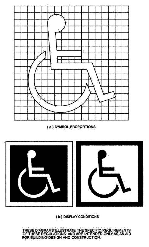
FIGURE 11A-1A—INTERNATIONAL ACCESSIBILITY SYMBOL
411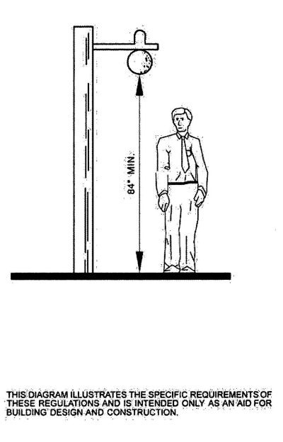
FIGURE 11A-1B—OVERHANGING OBSTRUCTION
412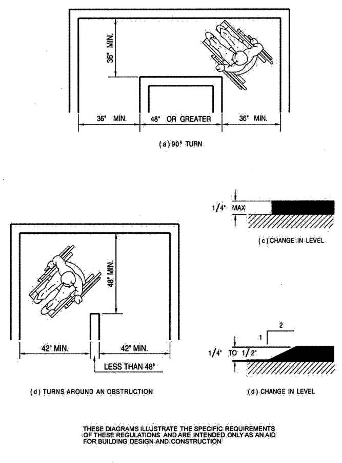
FIGURE 11A-1C—WIDTH OF ACCESSIBLE ROUTE
413
FIGURE 11A-1D—MINIMUM CLEAR WIDTH FOR TWO WHEELCHAIRS
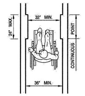
FIGURE 11A-1E—MINIMUM CLEAR WIDTH FOR SINGLE WHEELCHAIR
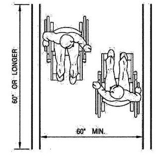
FIGURE 11A-1F—MINIMUM CLEAR WIDTH FOR TWO WHEELCHAIRS
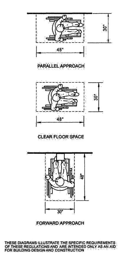
FIGURE 11A-1G—MINIMUM CLEAR FLOOR SPACE FOR WHEELCHAIRS
415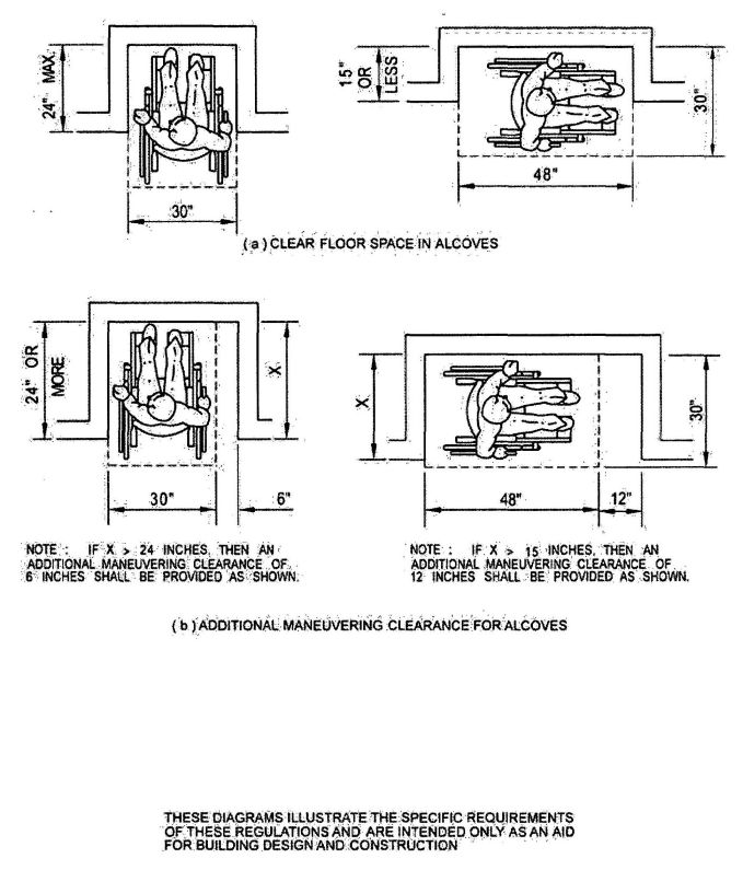
FIGURE 11A-1H—MINIMUM CLEAR FLOOR SPACE FOR WHEELCHAIRS
416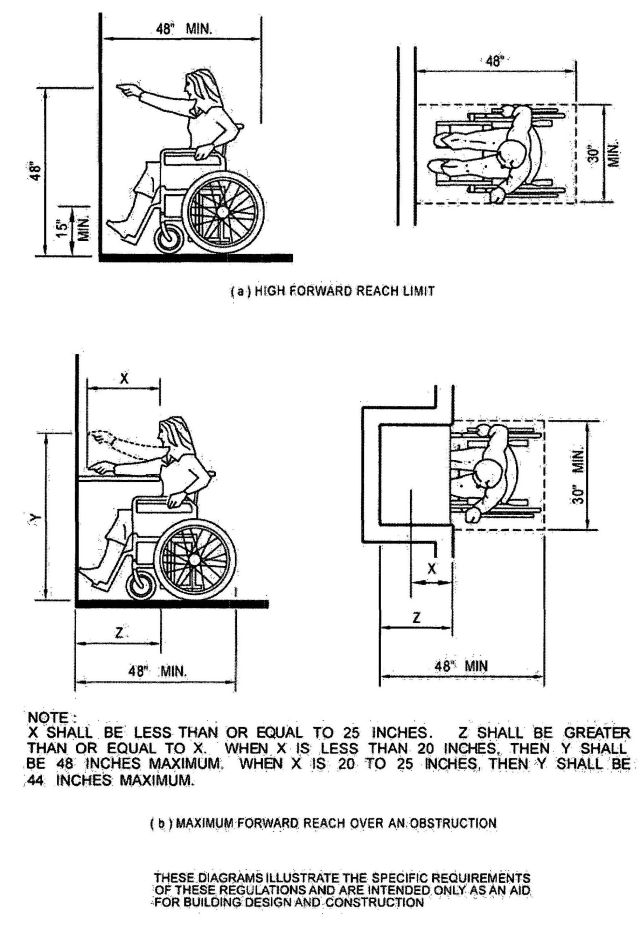
FIGURE 11A-11—FORWARD REACH
417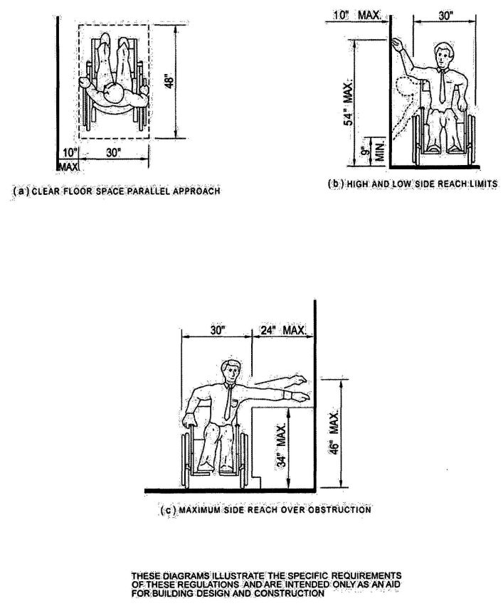
FIGURE 11A-1J—SIDE REACH
418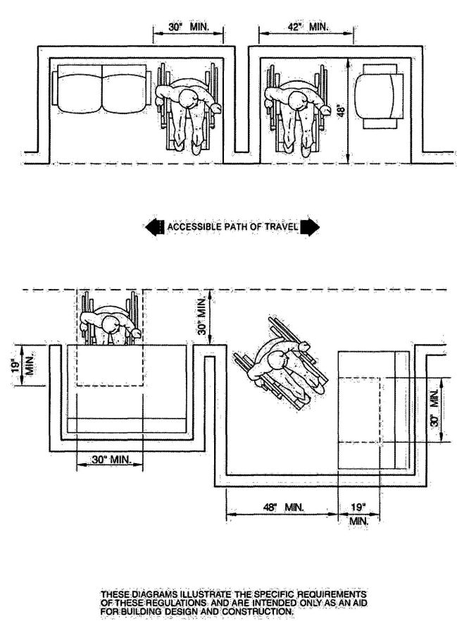
FIGURE 11A-1K—MINIMUM CLEARANCES FOR SEATING AND TABLE
419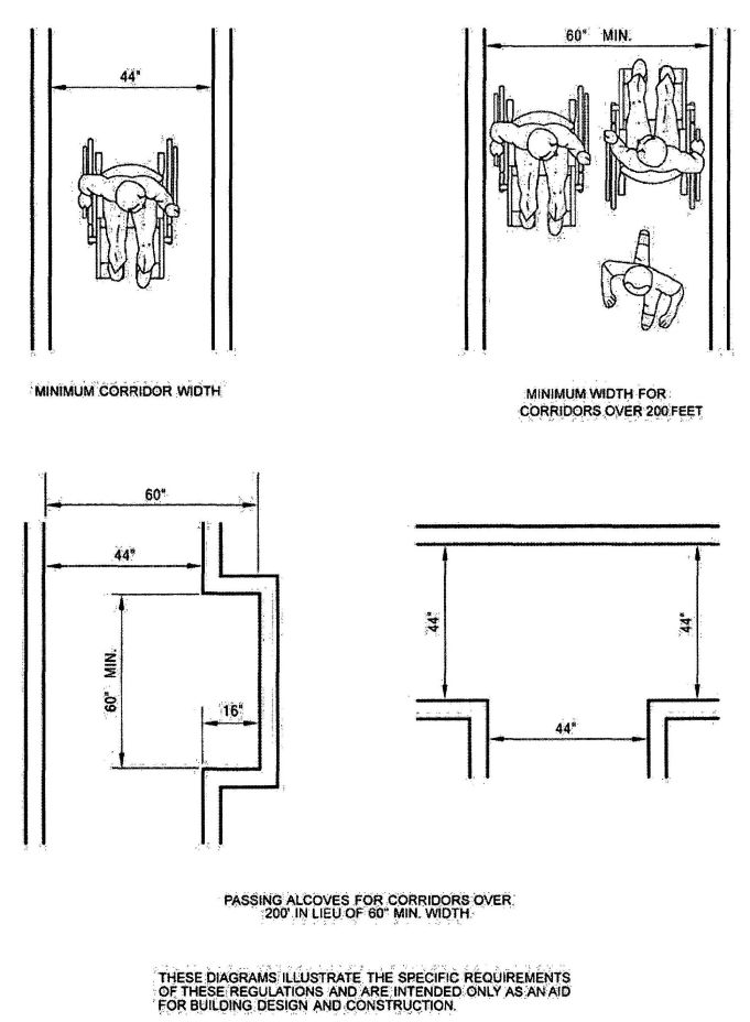
FIGURE 11A-1L—CORRIDOR OVER 200 FEET (60 960 mm)
420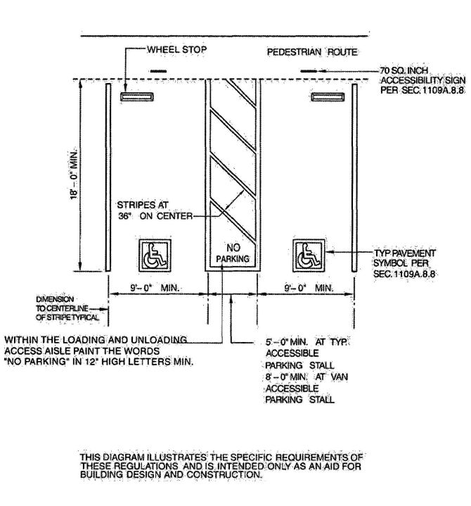
FIGURE 11A-2A—DOUBLE PARKING STALLS
421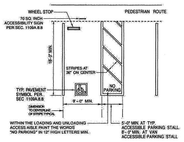
FIGURE 11A-2B—SINGLE AND VAN ACCESSIBLE PARKING STALLS
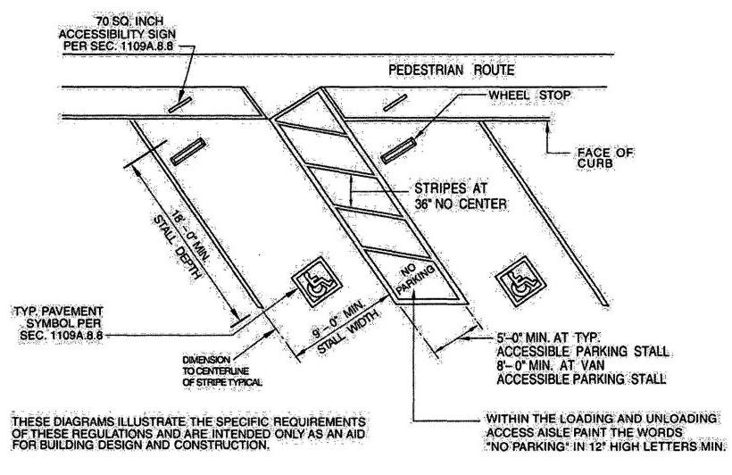
FIGURE 11A-2C—DIAGONAL PARKING STALLS
422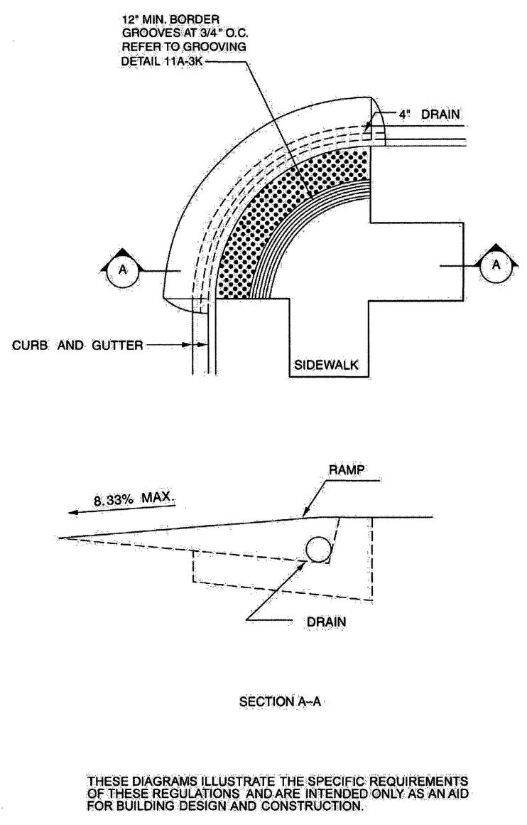
FIGURE 11A-3A—CURB DETAILS
423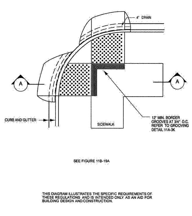
FIGURE 11A-3B—CURB DETAIL
424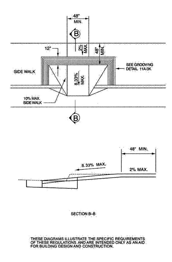
FIGURE 11A-3C—CURB DETAIL
425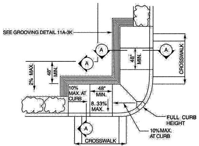
FIGURE 11A-3D—CURB DETAIL
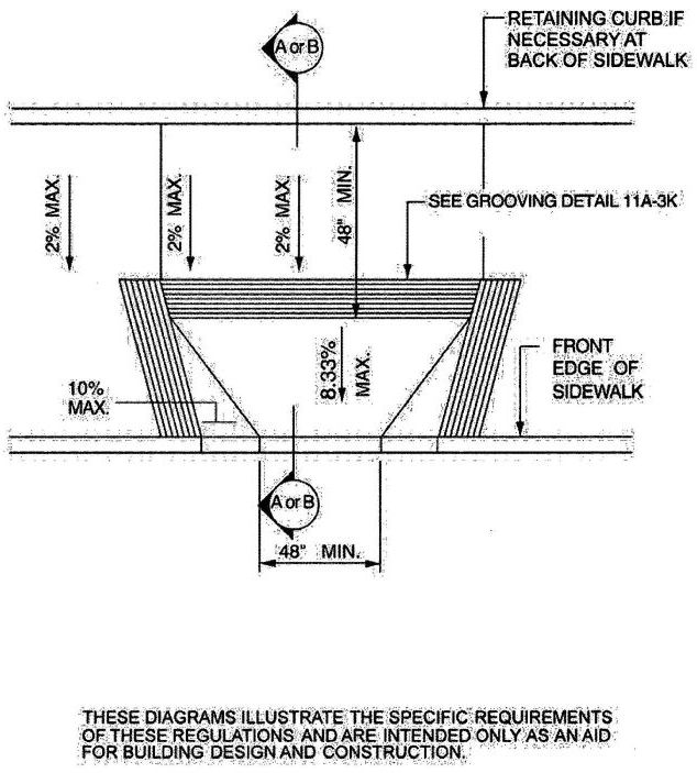
FIGURE 11A-3E—CURB DETAIL
426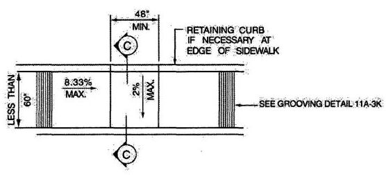
FIGURE 11A-3F—CURB DETAIL
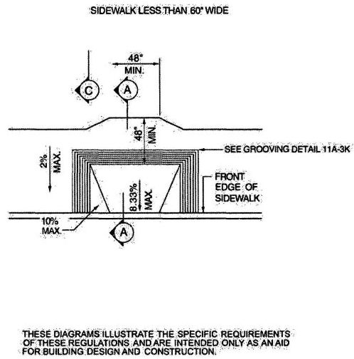
FIGURE 11A-3G—CURB DETAIL
427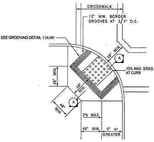
FIGURE 11A-3H—CURB DETAIL
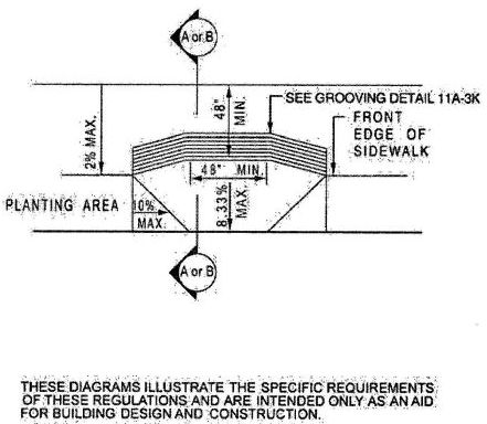
FIGURE 11A-3I—CURB DETAIL
428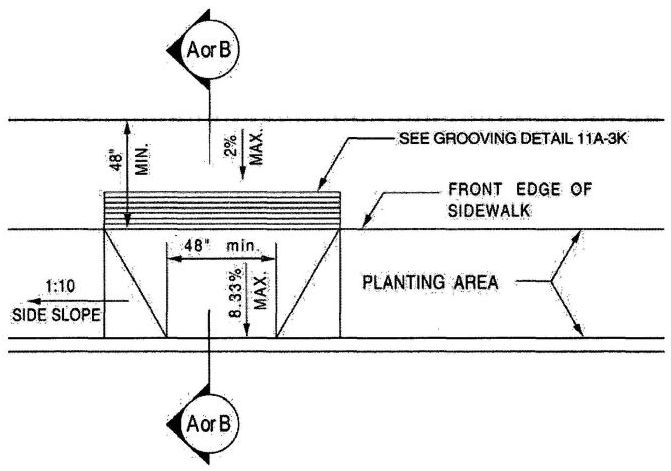
FIGURE 11A-3J—CURB DETAIL
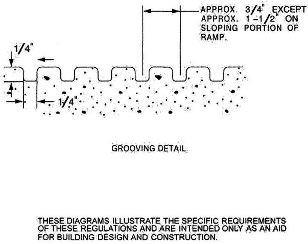
FIGURE 11A-3K—CURB DETAIL
429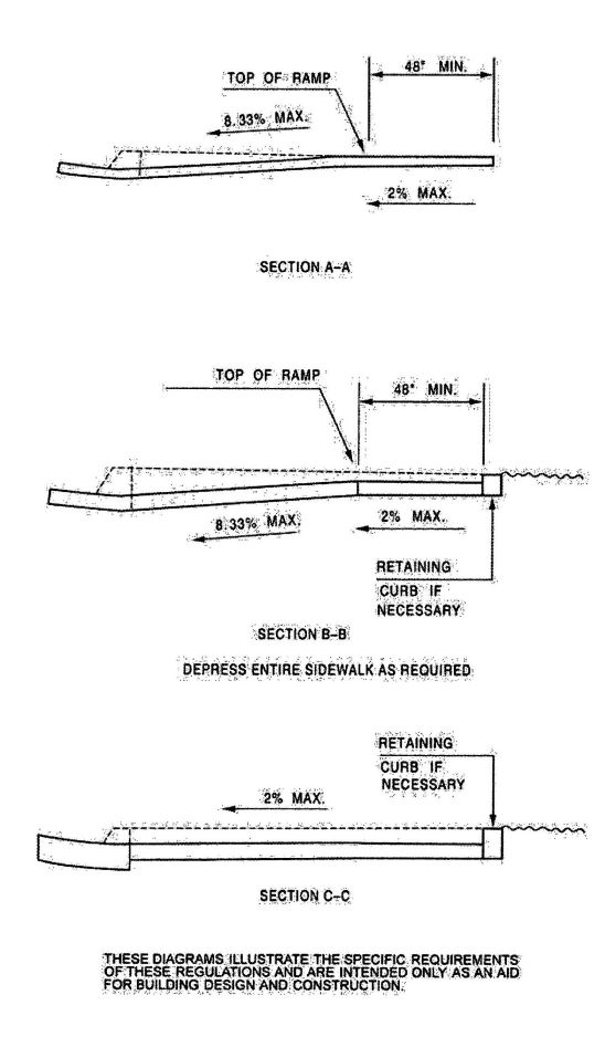
FIGURE 11A-3L—CURB SECTIONS
430FIGURE 11A-3M - RETURNED CURB STYLE (See Figure 11B-21)
FIGURE 11A-3N - TRUNCATED DOMES (See Figure 11B-23A)
FIGURE 11A-3—(RESERVED)
431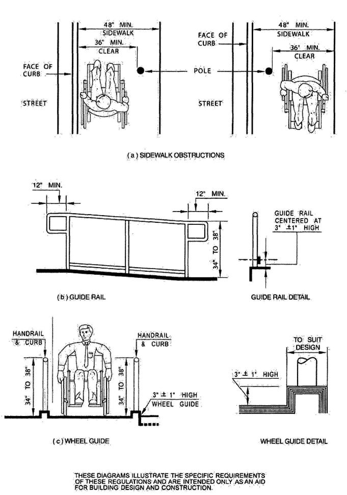
FIGURE 11A-5A—RAMPS AND SIDEWALKS
432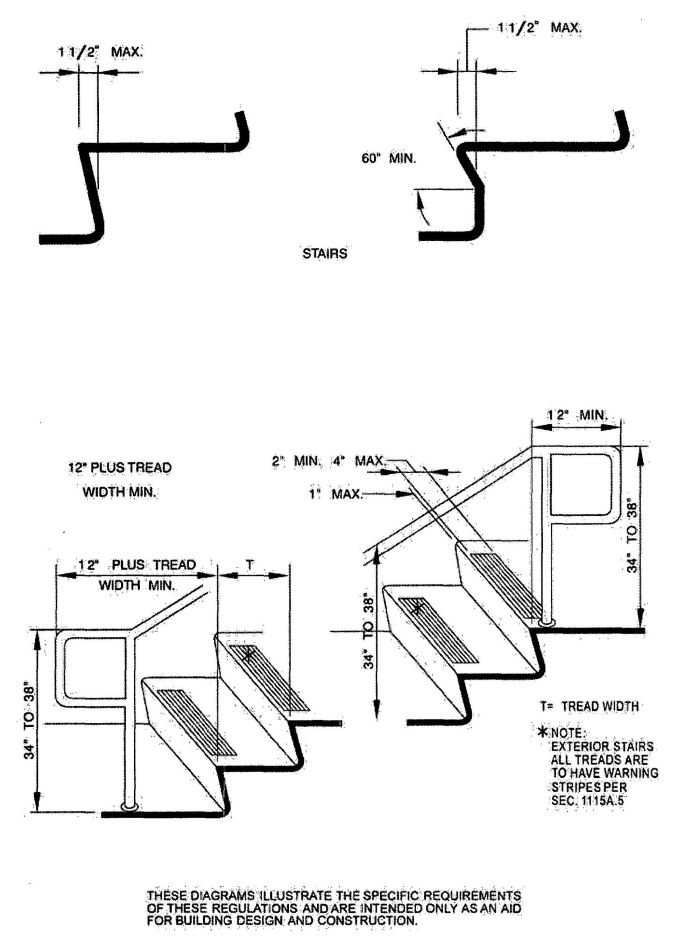
FIGURE 11A-6A—WARNING STRIPING AND HANDRAIL EXTENSIONS
433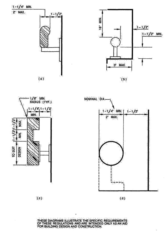
FIGURE 11A-6B—STAIR HANDRAILS
434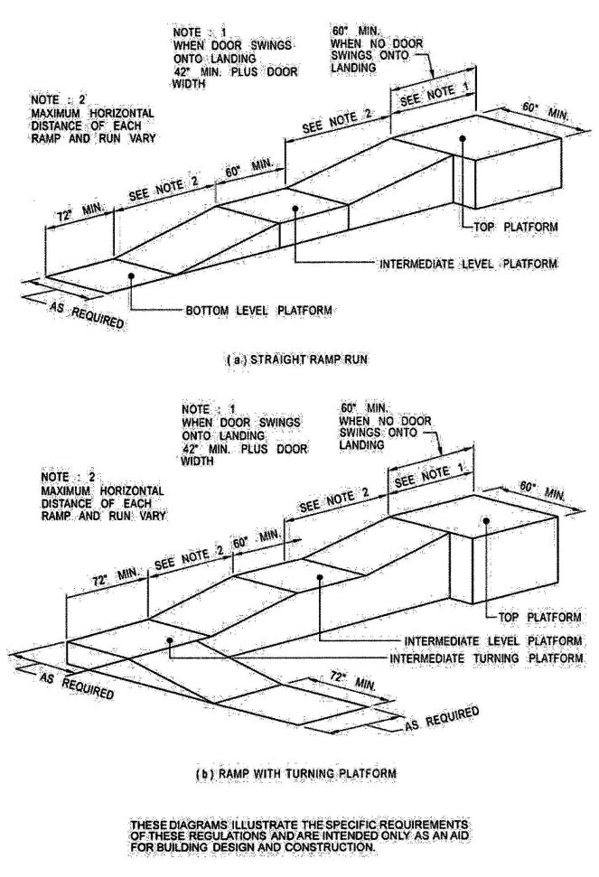
FIGURE 11A-6C—RAMP DIMENSIONS
435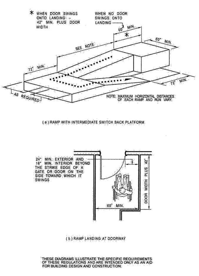
FIGURE 11A-6D—RAMP LANDING AND DOORWAY
436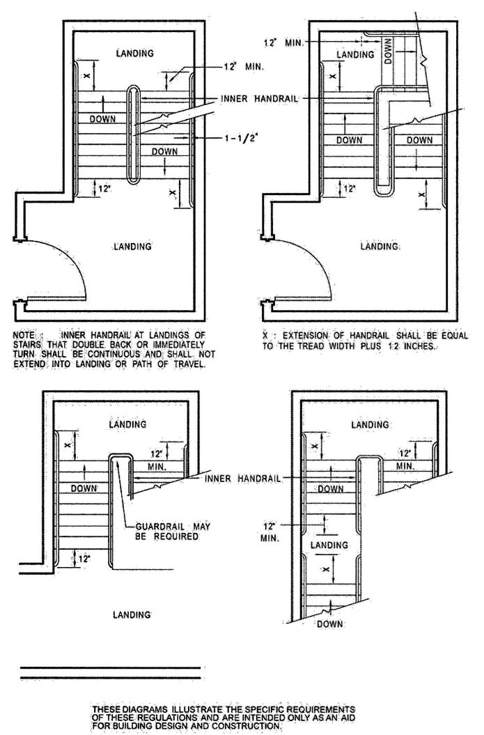
FIGURE 11A-6E—STAIR HANDRAILS
437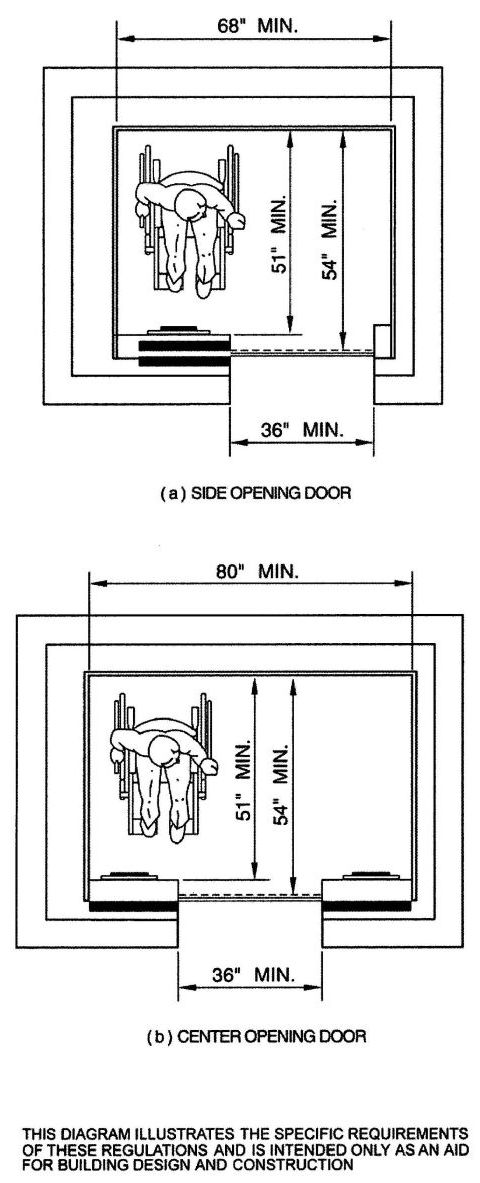
FIGURE 11A-7A—MINIMUM DIMENSIONS OF ELEVATOR CARS
438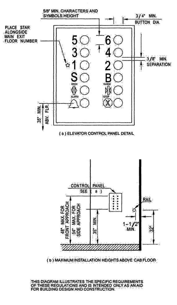
FIGURE 11A-7B—ELEVATOR CONTROL PANEL
439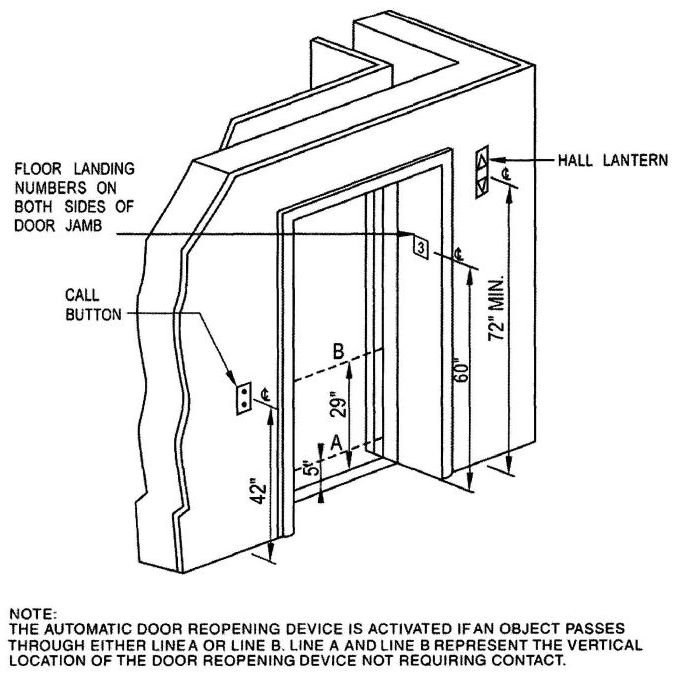
FIGURE 11A-7C—HOISTWAY AND ELEVATOR ENTRANCES
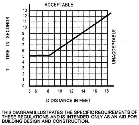
FIGURE 11A-7D—GRAPH OF TIMING EQUATION
440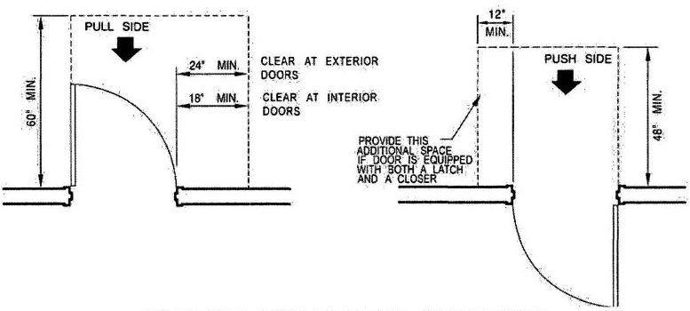
FIGURE 11A-8A—FRONT APPROACHES—SWINGING DOORS
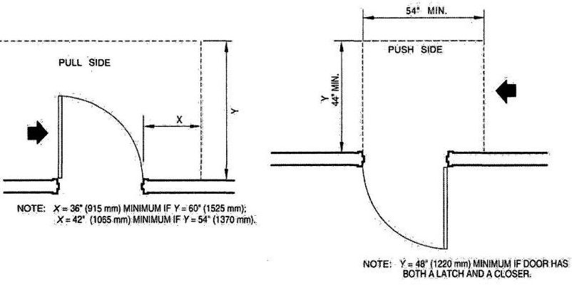
FIGURE 11A-8B—HINGE-SIDE APPROACHES—SWINGING DOORS
THESE DIAGRAMS ILLUSTRATE THE SPECIFIC REQUIREMENTS OF THESE REGULATIONS AND ARE INTENDED ONLY AS AN AID FOR BUILDING DESIGN AND CONSTRUCTION.
441LEVEL MANEUVERING CLEARANCE AT DOORS
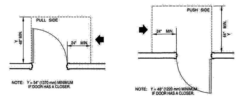
FIGURE 11A-8C—LATCH-SIDE APPROACHES—SWINGING DOORS
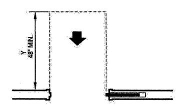
FIGURE 11A-8D—FRONT APPROACH—SLIDING DOORS AND FOLDING DOORS
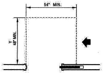
FIGURE 11A-8E—SLIDE SIDE APPROACH—SLIDING DOORS AND FOLDING DOORS
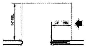
FIGURE 11A-8F—LATCH SIDE APPROACH—SLIDING DOORS AND FOLDING DOORS
THESE DIAGRAMS ILLUSTRATE THE SPECIFIC REQUIREMENTS OF THESE REGULATIONS AND ARE INTENDED ONLY AS AN AID FOR BUILDING DESIGN AND CONSTRUCTION.
LEVEL MANEUVERING CLEARANCE AT DOORS (Continued)
442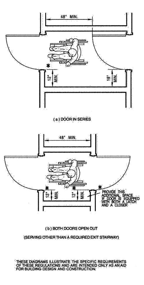
FIGURE 11A-8G—VESTIBULE
443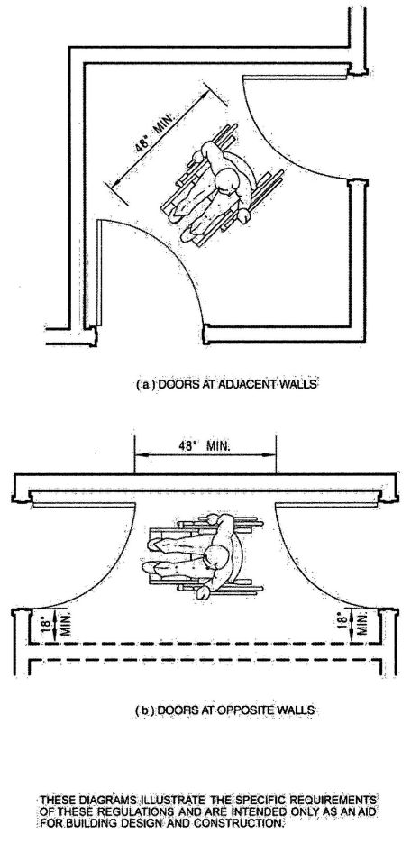
FIGURE 11A-8H—VESTIBULE (SERVING OTHER THAN A REQUIRED EXIT STAIRWAY)
444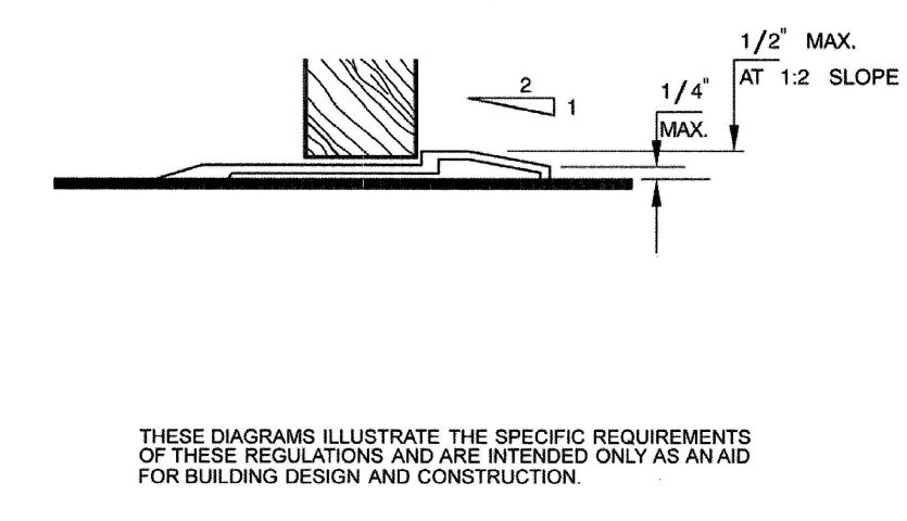
FIGURE 11A-8I—THRESHOLDS
445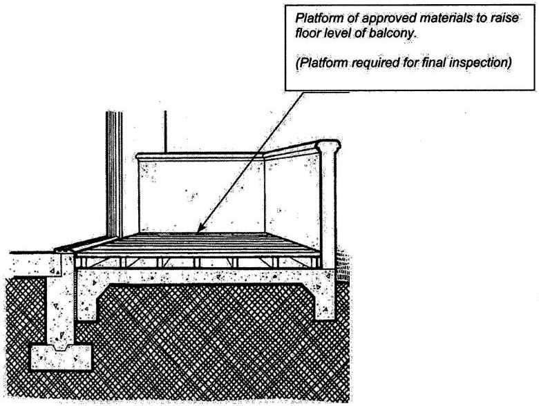
FIGURE 11A-8J—PLATFORM SECONDARY EXTERIOR DOOR
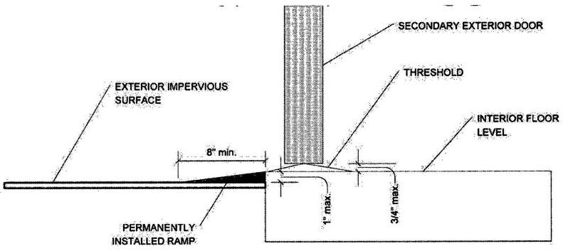
FIGURE 11A-8K—RAMP AT SECONDARY EXTERIOR DOOR
446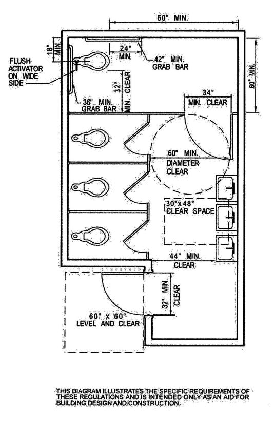
FIGURE 11A-9A—MULTIPLE ACCOMMODATION TOILET FACILITY
447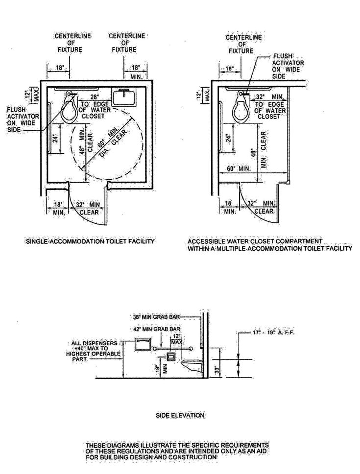
FIGURE 11A-9B
448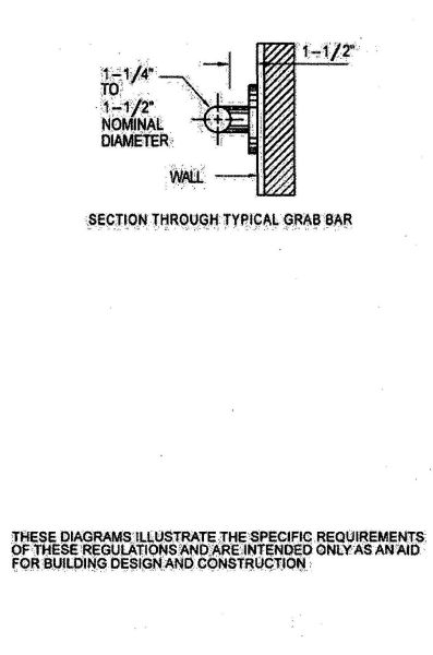
FIGURE 11A-9C—GRAB BAR SECTION
449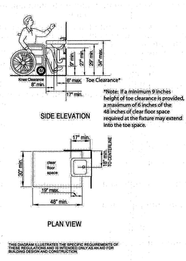
FIGURE 11A-9D—KNEE CLEARANCE
450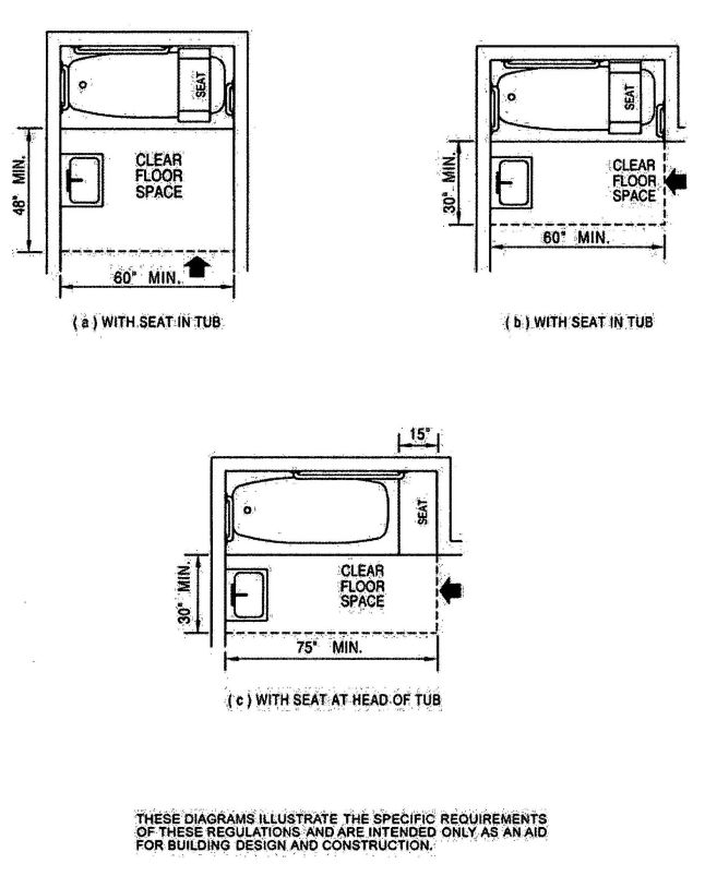
FIGURE 11A-9E—CLEAR FLOOR SPACE AT BATHTUBS
451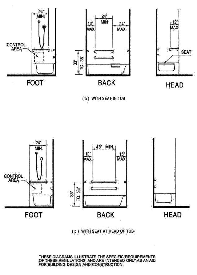
FIGURE 11A-9F—GRAB BARS AT BATHTUBS
452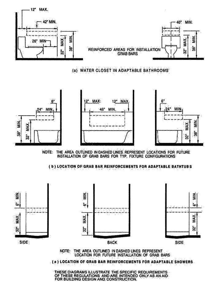
FIGURE 11A-9G
453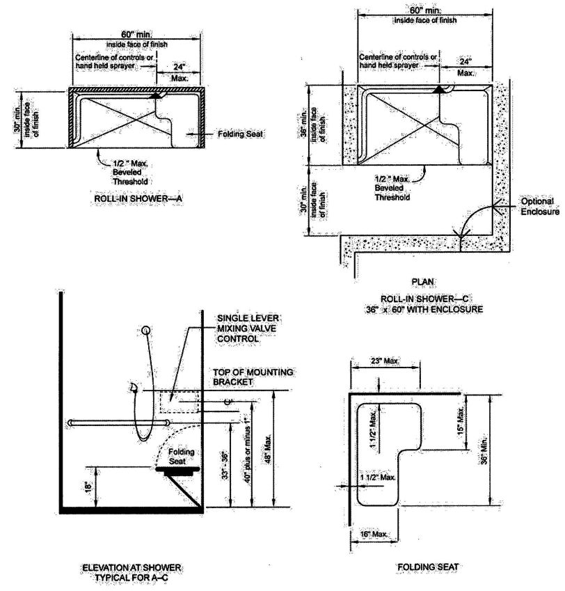
FIGURE 11A-9H—ROLL-IN SHOWER
454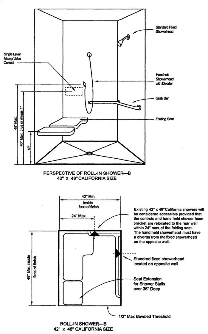
FIGURE 11A-9I—ROLL-IN SHOWER
455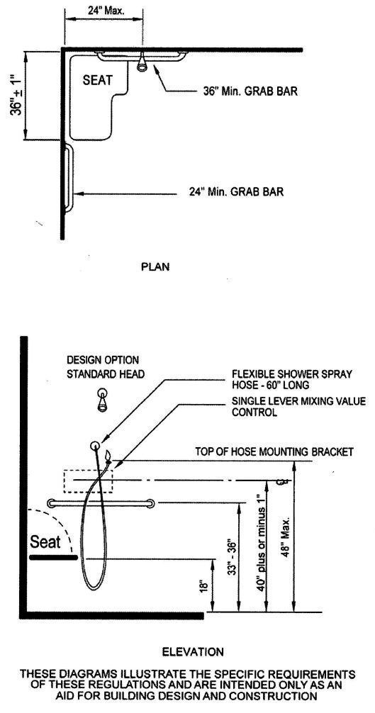
FIGURE 11A-9J—OPEN SHOWER
456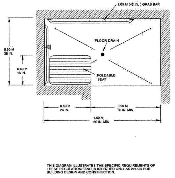
FIGURE 11A-9K—ALTERNATIVE ROLL-IN
457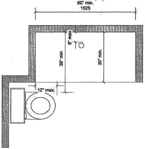
FIGURE 11A-9L—SHOWER WITH WATER CLOSET
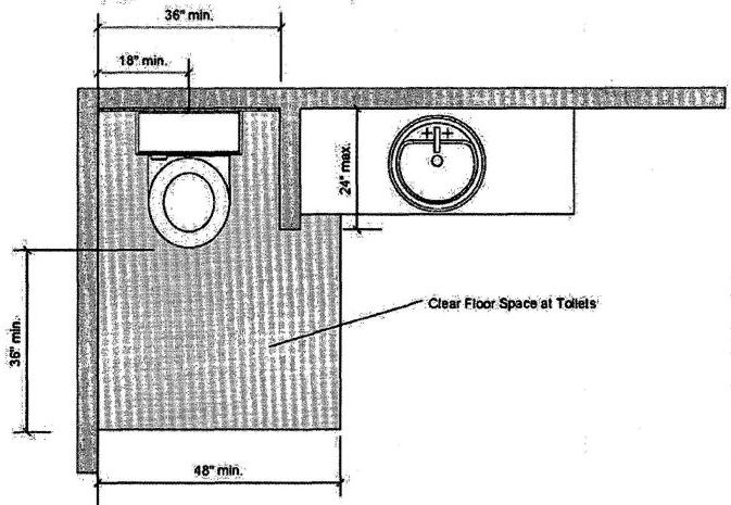
FIGURE 11A-9M—WING WALL OR CABINET AT WATER CLOSET
458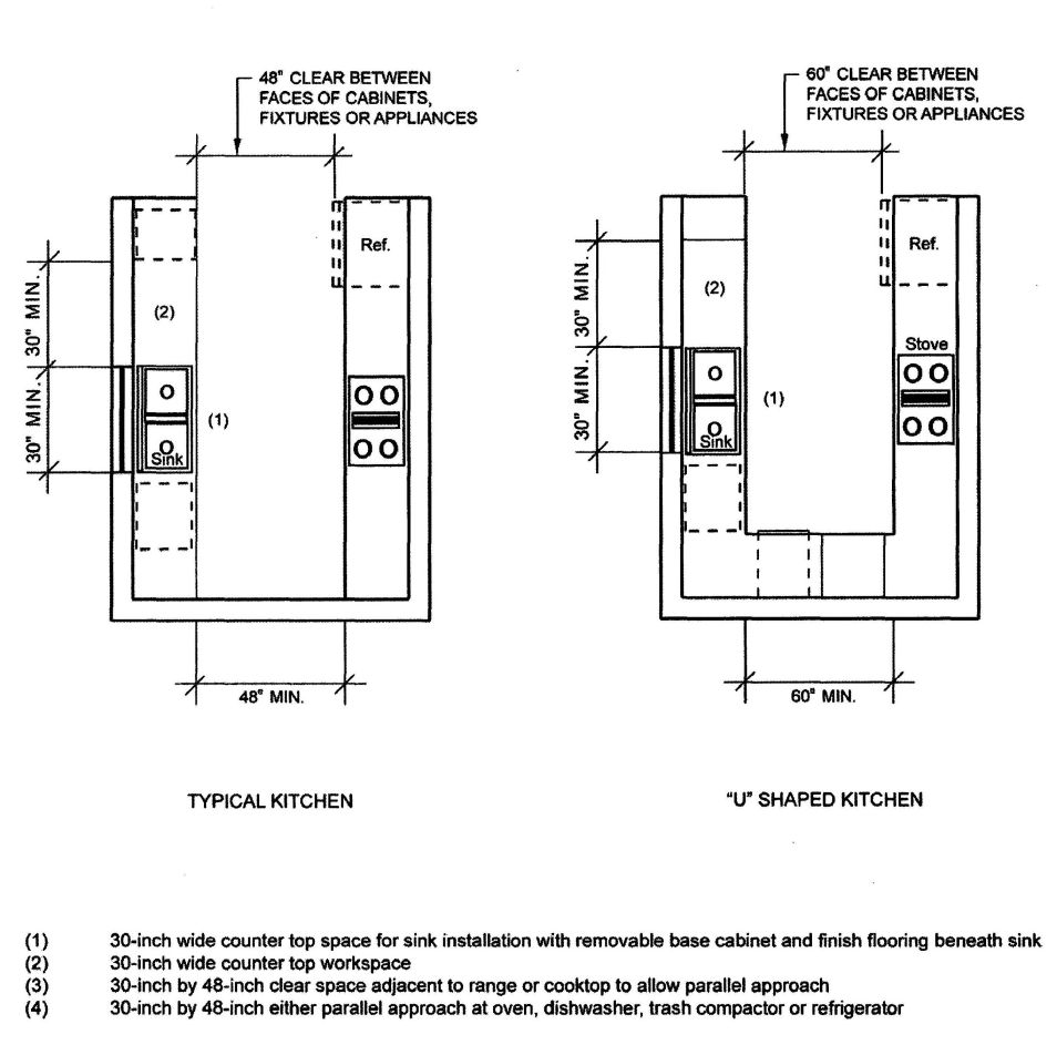
FIGURE 11A-10A—KITCHEN SPECIFICATIONS
459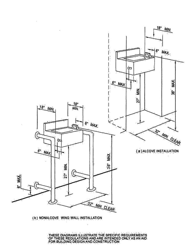
FIGURE 11A-11A—WATER FOUNTAINS
460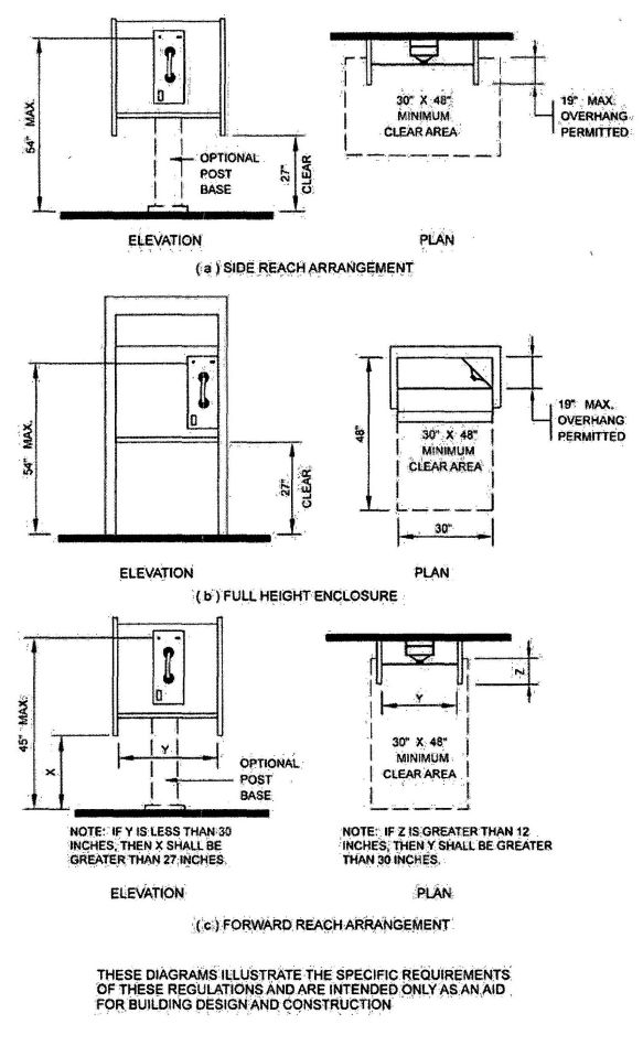
FIGURE 11A-11B—MOUNTING HEIGHTS AND CLEARANCES FOR TELEPHONES
461
FIGURE 11A-11C—INTERNATIONAL TTY SYMBOL

FIGURE 11A-11D—VOLUME CONTROL TELEPHONES

FIGURE 11A-11E—INTERNATIONAL SYMBOL OF ACCESS FOR HEARING LOSS
THESE DIAGRAMS ILLUSTRATE THE SPECIFIC REQUIREMENTS OF THESE REGULATIONS AND ARE INTENDED ONLY AS AN AID FOR BUILDING DESIGN AND CONSTRUCTION.
462| Adopting agency | BSC | SFM | HCD | DSA | OSHPD | CSA | DPH | AGR | DWR | CEC | CA | SL | SLC | |||||||
|---|---|---|---|---|---|---|---|---|---|---|---|---|---|---|---|---|---|---|---|---|
| 1 | 2 | 1-AC | AC | SS | SS/CC | 1 | 2 | 3 | 4 | |||||||||||
| Adopt entire chapter | Χ | |||||||||||||||||||
| Adopt entire chapter as amended (amended sections listed below) | ||||||||||||||||||||
| Adopt only those sections that are listed below | Χ | |||||||||||||||||||
| Chapter/Section | ||||||||||||||||||||
| 1114B.2.1 | Χ | |||||||||||||||||||
Note: For housing accessibility, see Chapter 11A.
Division 1 - NEW BUILDINGS
See Chapter 1, Section 1.9.1.5.
1101B.1 General.
1101B.2 Design. The design and construction of accessible building and facility elements shall be in accordance with this chapter.
1101B.3 Maintenance of accessible features.
1101B.4 Dimension conventions. Dimensions that are not stated as “maximum” or “minimum” are absolute.
1101B.5 Construction and manufacturing tolerances All dimensions are subject to conventional industry tolerances except where the requirement is stated as a range with specific minimum and maximum end points.
1101B.6 Commercial facilities located in private residences.
1101B.7 Provisions for adults. Unless otherwise indicated, the dimensions and specifications in these regulations are based upon adult dimensions and anthropometrics.
For additional definitions pertinent to the Division of the State Architect-Access Compliance accessibility requirements, see Chapter 2, Section 202.
For the purpose of the chapter, certain terms are defined as follows:
ACCESS AISLE is an accessible pedestrian space adjacent to or between parking spaces that provides clearances in conformance with this chapter.
ACCESSIBILITY is the combination of various elements in a building, facility, site, or area, or portion thereof which allows access, circulation and the full use of the building and facilities by persons with disabilities in conformance with this chapter.
ACCESSIBLE is approachable and usable by persons with disabilities in compliance with this code.
ACCESSIBLE ELEMENT is an element specified by the regulations adopted by the Division of the State Architect-Access Compliance.
ACCESSIBLE MEANS OF EGRESS. See Section 1002.1.
ACCESSIBLE ROUTE OF TRAVEL is a continuous unobstructed path connecting all accessible elements and spaces in an accessible building or facility that can be negotiated by a person with a disability using a wheelchair and that is also safe for and usable by persons with other disabilities, and that is consistent with the definition of “Path of travel” in this section. Interior accessible routes may include corridors, floors, ramps, elevators, lifts and clear floor space at fixtures. Exterior accessible routes may include parking access aisles, curb ramps, crosswalks at vehicular ways, walks, sidewalks, ramps, and lifts. An accessible route does not include stairs, steps or escalators.
465ACCESSIBLE SPACE is a space that complies with the regulations adopted by the Division of the State Architect-Access Compliance.
ADAPTABILITY is the capability of spaces or facilities to be readily modified and made accessible.
ADMINISTRATIVE AUTHORITY is a governmental agency that adopts or enforces regulations and guidelines for the design, construction, or alteration of buildings and facilities.
AISLE is a circulation path between objects such as seats, tables, merchandise, equipment, displays, shelves, desks, etc., that provides clearances in conformance with this chapter.
AISLE, EMPLOYEE AREAS (as required for architectural accessibility) is a space that serves as a passageway, which is created by architectural components such as walls, fixed cabinetry or fixtures and not moveable components such as furniture.
AREA OF REFUGE. See Section 1002.1.
ASSEMBLY AREA is a room or space accommodating a group of individuals for recreational, educational, political, social or amusement purposes, or for the consumption of food and drink.
AUTOMATIC DOOR is a door equipped with a power operated mechanism and controls that open and close the door automatically upon receipt of a momentary actuating signal. The switch that begins the automatic cycle may be a photoelectric device, floor mat or manual switch.
CIRCULATION PATH is an exterior or interior way of passage from one place to another for pedestrians, including, but not limited to, walks, hallways, courtyards, stairways and stair landings.
CLEAR means unobstructed.
CLEAR FLOOR SPACE is the minimum unobstructed floor of ground space required to accommodate a single, stationary wheelchair and occupant.
CLOSED-CIRCUIT TELEPHONE is a telephone with dedicated line(s) such as a house phone, courtesy phone or phone that must be used to gain entrance to a facility.
COMMON USE AREAS are those interior and exterior rooms, spaces or elements that are made available for the use of a restricted group of people (for example, occupants of a homeless shelter, the occupants of an office building or the guests of such occupants).
COMPLY WITH means to meet one or more specifications of these regulations.
CROSS SLOPE is the slope that is perpendicular to the direction of travel (as differentiated from running slope).
CURB CUT is an interruption of a curb at a pedestrian way, which separates surfaces that are substantially at the same elevation.
CURB RAMP is a sloping pedestrian way, intended for pedestrian traffic, which provides access between a walk or side walk and a surface located above or below an adjacent curb face, as differentiated from a ramp.
DETECTABLE WARNING is a standardized surface or feature built into or applied to walking surfaces or other elements to warn visually impaired persons of hazards in the path of travel. Only approved DSA-AC detectable warning products and directional surfaces shall be installed as provided in the California Code of Regulations (CCR). Title 24, Part 1, Articles 2, 3 and 4. Refer to CCR Title 24, Part 12, Chapter 12-11A and B for building and facility access specifications for product approval for detectable warning products and directional surfaces.
Detectable warning products and directional surfaces installed after January 1, 2001, shall be evaluated by an independent entity, selected by the Department of General Services, Division of the State Architect-Access Compliance, for all occupancies, including transportation and other outdoor environments, except that when products and surfaces are for use in residential housing, evaluation shall be in consultation with the Department of Housing and Community Development. See Government Code Section 4460.
DWELLING UNIT is a single unit of residence for a family of one or more persons. Examples of dwelling units covered by this chapter include condominiums, an apartment unit within an apartment building and other types of a dwellings in which sleeping accommodations are provided but toileting or cooking facilities are shared by occupants of more than one room or portion of the dwelling. Examples of the latter include dormitory rooms and sleeping accommodations in shelters intended for occupancy as residences for homeless persons.
ELEMENT is an architectural or mechanical component of a buildings, facility, space or site; for example, a telephone, curb ramp, door, drinking fountain, seating or water closet.
ELEVATOR, PASSENGER is an elevator used primarily to carry passengers.
ENTRANCE means any access point to a building or portion of a building or facility used for the purpose of entering. An entrance includes the approach walk, the vertical access leading to the entrance platform, the entrance platform itself, vestibules if provided, the entry door(s) or gate(s), and the hardware of the entry door(s) or gate(s).
EQUIVALENT FACILITATION is an alternate means of complying with the literal requirements of these standards and specifications that provides access in terms of the purpose of these standards and specifications. See Section 1.9.1.5.
EXIT. See Section 1002.1.
FACILITY (or FACILITIES) is a building, structure, room, site, complex or any portion thereof that is built, altered, improved or developed to serve a particular purpose. Facilities shall include all or any portion of buildings, structures, site developments, complexes, equipment, roads, walks, side walks, passageways, parking lots or other real or personal property located on a site.
GRAB BAR is a bar for the purpose of being grasped by the hand for support.
GUARD (or GUARDRAIL). See Section 1002.1.
HANDRAIL. See Section 1002.1.
466HEALTH CARE PROVIDER. See “Professional office of a health care provider.”
IF, IF…THEN denotes a specification that applies only when the conditions described are present.
INDEPENDENT ENTITY. See Section 202. Detectable warning products and directional surfaces installed after January 1, 2001, shall be evaluated by an independent entity, selected by the Department of General Services, Division of the State Architect-Access Compliance, for all occupancies, including transportation and other outdoor environments, except that when products and surfaces are for use in residential housing evaluation shall be in consultation with the Department of Housing and Community Development. See Government Code Section 4460.
INTERNATIONAL SYMBOL OF ACCESSIBILITY is that symbol adopted by Rehabilitation International’s 11th World Congress for the purpose of indicating that buildings and facilities are accessible to persons with disabilities. See Figure 11B-6.
KICK PLATE is an abrasion-resistant plate affixed to the bottom portion of a door to prevent a trap condition and protect its surface.
LEVELAREA is a specified surface that does not have a slope in any direction exceeding one unit vertical in 50 units horizontal (2-percent slope).
LIFT, PLATFORM (WHEELCHAIR). See “Platform (Wheelchair) Lift.”
MARKED CROSSING is a crosswalk or other identified path intended for pedestrian use in crossing a vehicular way.
MAY denotes an option or alternative.
NEWLY CONSTRUCTED. See Chapter 11A, Section 1107A.14-N.
NOSE, NOSING is that portion of a stair tread or landing at the top of a stairway flight projecting beyond the face of the riser immediately below.
OPEN RISER is the space between two adjacent stair treads not closed by a riser.
OPERABLE PART is a part of a piece of equipment or appliance used to insert or withdraw objects, or to activate, deactivate or adjust the equipment or appliance (for example, coin slot, pushbutton, handle).
PASSAGE DOOR is a door other than an exit door through which persons may traverse.
PATH OF TRAVEL is a passage that may consist of walks and sidewalks, curb ramps and pedestrian ramps, lobbies and corridors, elevators, other improved areas or a necessary combination thereof, that provides free and unobstructed access to and egress from a particular area or location for pedestrians and/or wheelchair users. A ”path of travel” includes a continuous, unobstructed way of pedestrian passage by means of which a particular area may be approached, entered and exited, and which connects a particular area with an exterior approach (including sidewalks, streets, and parking areas), an entrance to the facility, and other parts of the facility. In existing buildings, when alterations, structural repairs or additions are made, the term “path of travel” also includes the sanitary facilities, telephones, drinking fountains and signs serving the altered area.
PEDESTRIAN is an individual who moves in walking areas with or without the use of walking assistive devices such as crutches, leg braces, wheelchairs, white cane, service animal, etc.
PEDESTRIAN GRADE SEPARATION is a structure erected over or under an obstacle such as a freeway, roadway, street, railroad, stream, etc., and intended primarily for pedestrian use.
PEDESTRIAN RAMP is a walking surface which has a running slope greater than 1:20 intended for pedestrian traffic and as differentiated from a curb ramp.
PEDESTRIAN WAY is a route by which a pedestrian may pass.
PLATFORM. See Section 410.2.
PLATFORM (WHEELCHAIR) LIFT is a hoisting and lowering mechanism equipped with a car or platform or support that serves two landings of a building or structure and is designed to carry a passenger or passengers and (or) luggage or other material a vertical distance as may be allowed.
PROFESSIONAL OFFICE OF A HEALTH CARE PROVIDER is a location where a person or entity, regulated by the State to provide professional services related to the physical or mental health of an individual, makes such services available to the public. The facility housing the professional office of a health care provider only includes floor levels housing at least one health care provider, or any floor level designed or intended for use by at least one health care provider.
PUBLIC USE AREA means interior or exterior rooms or spaces of a building that are made available to the general public and does not include common use areas. Public use areas may be provided at a building that is privately or publicly owned.
PUBLIC WAY. See Section 1002.1.
RAMP is a walking surface which has a running slope greater than one unit vertical in 20 units horizontal (5-percent slope) intended for pedestrian traffic and as differentiated from a curb ramp.
RISER is the upright member between two adjacent stair treads.
RUNNING SLOPE is the slope that is parallel to the direction of travel (as differentiated from cross slope).
SHALL denotes a mandatory specification or requirement.
SHOPPING CENTER (or SHOPPING MALL) is one or more sales or rental establishments or stores. A shopping center may include a series of buildings on a common site, connected by a common pedestrian access route on, above or below the ground floor, that is either under common ownership or common control or developed either as one project or as a series of related projects. For the purposes of this section, “shopping center” or “shopping mall” includes a covered mall building.
467SHOULD denotes an advisory specification or recommendation.
SIDEWALK. See Section 202.
SLEEPING ACCOMMODATIONS are rooms in which people may sleep; for example, dormitory and hotel or motel guest rooms or suites.
SPECIFIED PUBLIC TRANSPORTATION is transportation by bus, rail or any other conveyance (other than by aircraft) that provides the general public with general or special service (including charter service) on a regular and continuing basis.
STAGE. See Section 410.2.
STAIR. See Section 1002.1.
STAIRWAY. See Section 1002.1.
STORY means that portion of a building included between the upper surface of any floor and the upper surface of the floor next above, except that the topmost story shall be that portion of a building included between the upper surface of the topmost floor and the ceiling or roof above. If the finished floor level directly above a basement or unused under-floor space is more than 6 feet (1829 mm) above grade for more than 50 percent of the total perimeter or is more than 12 feet (3658 mm) above grade at any point, the basement or unused under-floor space shall be considered as a story. There may be more than one floor level within a story as in the case of a mezzanine or mezzanines.
STORY, FIRST means the lowest story in a building which qualifies as a story and which provides the basic services or functions for which the building is used. A floor level in a building having only one floor level shall be classified as a first story, if the floor level is not more than 4 feet (1219 mm) below grade, for more than 50 percent of the total perimeter, or more than 8 feet (2438 mm) below grade at any point.
STRUCTURAL FRAME is considered to be the columns and the girders, beams, trusses and spandrels having direct connections to the columns and all other members which are essential to the stability of the building as a whole.
TEXT TELEPHONE is machinery or equipment that employs interactive text-based communications through the transmission of coded signals across the standard telephone network. Text telephones can include, for example, devices known as TTYs (teletypewriters) or computers.
TRANSIENT LODGING is a building, facility or portion thereof, excluding inpatient medical care facilities, that contains one or more dwelling units or sleeping accommodations. Transient lodging may include, but is not limited to, resorts, group homes, hotels, motels and dormitories.
TRANSIT BOARDING PLATEFORM is a horizontal, generally level surface, whether raised above, recessed below or level with a transit rail, from which persons embark/disembark a fixed rail vehicle.
TREAD is the horizontal member of a step.
VEHICULAR WAY is a route intended for vehicular traffic, such as a street, driveway or parking lot.
WALK is a surfaced pedestrian way not located contiguous to a street used, by the public. (As differentiated from the definition of “Sidewalk” in Section 202.)
WORK STATION is an area defined by equipment and/or work surfaces intended for use by employees only, and generally for one or a small number of employees at a time. Examples include ticket booths; the employee side of grocery store checkstands; the bartender area behind a bar; the employee side of snack bars, sales counters and public counters; guard-houses; toll booths; kiosk vending stands; lifeguard stations; maintenance equipment closets; counter and equipment areas in restaurant kitchens; file rooms; storage areas; etc.
1103B.1 Scope. Accessibility to buildings or portions of buildings shall be provided for all occupancy classifications except as modified or enhanced by this chapter. Occupancy requirements in this chapter may modify general requirements, but never to the exclusion of them. When a building or facility contains more than one use, the occupancy specific accessibility provisions for each portion of the building or facility shall apply.
An accessible route of travel complying with Section 1114B.1.2 shall connect all elements and spaces within a building or facility. Multistory buildings and facilities must provide access to each level, including mezzanines, by ramp or passenger elevator complying with Section 1116B. If more than one elevator is provided, each passenger elevator shall comply with Section 1116B.
Exceptions:
- Floors or portions of floors not customarily occupied, including, but not limited to, nonoccupiable or employee spaces accessed only by ladders, catwalks, crawl spaces, very narrow passageways or freight (nonpassenger) elevators, and frequented only by service personnel for repair or maintenance purposes, including, but not limited to, elevator pits and elevator penthouses, piping and equipment catwalks, and machinery rooms.
- The following types of privately funded multistory buildings do not require a ramp or elevator above and below the first floor:
- Multistoried office buildings (other than the professional office of a health care provider) and passenger vehicle service stations less than three stories high or less than 3,000 square feet (279 m2) per story.
- Any other privately funded multistoried building that is not a shopping center, shopping mall or the professional office of a health care provider, or a terminal, depot or other station used for specified public transportation, or an airport passenger terminal and that is less than three stories high or less than 3,000 square feet (279 m2) per story if a reasonable portion of all facilities and accommodations 468 normally sought and used by the public in such a building are accessible to and usable by persons with disabilities.
The elevator exception set forth in this section does not obviate or limit in any way the obligation to comply with the other accessibility requirements in this code. For example, floors above or below the accessible ground floor must meet the requirements of this section except for elevator service. If toilet or bathing facilities are provided on a level not served by an elevator, then toilet or bathing facilities must be provided on the accessible ground floor.
If a building or facility is eligible for this exception but a passenger elevator is nonetheless planned, that elevator shall meet the requirements of Section 1116B and shall serve each level in the building. A passenger elevator that provides service from a garage to only one level of a building or facility is not required to serve other levels.
In existing buildings, where elevators are required by Section 1134B.2 or 1103B.1, if an escalator or stair is installed where none existed previously and major structural modifications are necessary for such installation, then a means of accessible vertical access via ramp, elevator or lift shall be provided.
1103B.2 Distance to elevators. In new construction of buildings where elevators are required by Section 1103B.1, and which exceed 10,000 square feet (929 m2) on any floor, an accessible means of vertical access via ramp, elevator or lift shall be provided within 200 feet (60 960 mm) of travel of each stair and each escalator. In existing buildings that exceed 10,000 square feet (929 m2) on any floor and in which elevators are required by Sections 1134B.2 and 1103B.1, whenever a newly constructed means of vertical access is provided via stairs or an escalator, an accessible means of vertical access via ramp, elevator or lift shall be provided within 200 feet (60 960 mm) of travel of each new stair or escalator.
Exception: Stairs used solely for emergency egress.
1104B.1 General. All Group A occupancies shall be accessible as provided in this chapter. See also the general requirements in Section 1114B.1.1.
1104B.2 Assistive-listening systems in assembly areas. Assembly areas, conference and meeting rooms shall provide assistive-listening systems for persons with hearing impairments as provided in this section.
Exception: This section does not apply to systems used exclusively for paging, or background music, or a combination of these two uses.
1104B.3 Auditoriums, assembly halls, theaters and related facilities.
1104B.3.1 Seating. In all assembly places where seating is provided, there shall be spaces for persons using wheelchairs and semi-ambulant persons, as provided in this section.
Exceptions:
- In existing buildings and facilities when the enforcing agency determines that compliance with the seating requirements of this code would create an unreasonable hardship, such requirements shall not apply. When the unreasonable hardship finding is applied, at least 1 percent of the total seating provided shall be accessible to and usable by persons with disabilities who use wheelchairs, and such seating shall comply with the level requirements and the individual space requirements of this code.
- When an existing theater is subdivided into more than one facility having upper levels not accessible by ramp or elevator, and the enforcing agency determines that full compliance with this code would create an unreasonable hardship, such upper levels need not be made accessible, provided all facilities at grade are accessible and any event, showing of motion pictures or other activities469 made available to the public in all of the facilities are scheduled to ensure that all such functions are available to the public in the accessible facility.
1104B.3.2 Accessibility to key facilities. Seating for persons with disabilities shall be accessible from the main lobby or from a primary entrance, together with related toilet facilities.
1104B.3.3 Variety of locations. Accessible seating or accommodations in places of public amusement and resort, including theaters, concert halls and stadiums, shall be provided in a variety of locations so as to provide persons with disabilities a choice of admission prices otherwise available to members of the general public.
1104B.3.4 Wheelchair spaces.
| SEATING CAPACITY | NO. OF WHEELCHAIR SEATING SPACES |
|---|---|
| 4 to 25 | 1 |
| 26 to 50 | 2 |
| 51 to 300 | 4 |
| 301 to 500 | 6 |
In addition, 1 percent, but not less than one, of all fixed seats, shall be aisle seats with no armrests on the aisle side, or removable or folding armrests on the aisle side. Each such seat shall be identified by a sign or marker with the International Symbol of Accessibility (see Figure 11B.6). Signage notifying patrons of the availability of such seats shall be posted at the ticket office. Signs and markers shall comply with Section 1117B.5.1, Items 2 and 3, as applicable.
1104B.3.5 Placement of wheelchair locations. Wheelchair areas shall be an integral part of any fixed seating plan, and shall be arranged so as to provide persons with disabilities a choice of admission prices and lines of sight comparable to those for members of the general public. Each wheelchair area shall adjoin an accessible route which shall also serve as a means of egress in case of emergency. At least one companion fixed seat shall be provided next to each wheelchair seating area. When the seating capacity exceeds 300, wheelchair spaces shall be provided in more than one location in addition to complying with Section 1104B.3.3.
Exceptions:
- Accessible viewing positions where seating capacity is less than 300 may be clustered for bleachers, balconies and other areas having sight lines that require slopes of greater than one unit vertical in 20 units horizontal (5-percent slope). Equivalent accessible viewing positions may be located on levels having accessible egress.
- Where it is determined that dispersing accessible seating throughout an existing assembly area would create an unreasonable hardship, accessible seating areas may be clustered. Each accessible seating area shall have provisions for companion seating and shall have provisions for companion seating and shall be located on an accessible route that also serves as a means of emergency egress.
1104B.3.6 Size of wheelchair location. Each wheelchair location shall provide minimum clear floor or ground space as shown in Figure 11B-15, and shall adjoin an egress aisle on at least one side.
1104B.3.7 Removable seats. Readily removable seats may be installed in these wheelchair spaces when such spaces are not required to accommodate wheelchair users.
1104B.3.8 Seating for semi-ambulant individuals. In addition to spaces provided for wheelchair users as noted in Sections 1104B.3.4 through 1104B.3.7 above, there shall be provided seating for semi-ambulant individuals. The number of such seating shall be equal to at least 1 percent of the total seating and shall be no fewer than two. Such seats shall provide at least 24 inches (610 mm) clear leg space between the front of the seat to the nearest obstruction or to the back of the seat immediately in front.
1104B.3.9 Life safety. In determining the location of seating for persons with disabilities, life safety shall be considered, and all seating provided must comply with the fire and panic safety requirements of the State Fire Marshal.
1104B.3.10 Access to performing areas. An accessible route shall connect wheelchair seating locations with performing areas, including stages, arena floors, dressing rooms, locker rooms and other spaces used by performers.
1104B.3.11 Stages, enclosed and unenclosed platforms and orchestra pits. Stages, enclosed and unenclosed platforms and orchestra pits shall be made accessible to persons with disabilities.
470Exceptions:
- When the enforcing agency finds that requiring compliance with this code, for an enclosed or unenclosed platform or depressed area not more than 24 inches (610 mm) above or below an adjacent accessible level, would create an unreasonable hardship, the enclosed and unenclosed platform or depressed area shall be made accessible by a portable ramp with a slope not exceeding one unit vertical in 12 units horizontal (8.33 percent slope).
- In existing buildings and facilities, all stages, enclosed or unenclosed platforms, and orchestra pits need not be accessible when the enforcing agency determines that compliance with this code would create an unreasonable hardship.
1104B.3.12 Ticket booths. Customer and employee sides of ticket booths and of concession and refreshment sales facilities shall be made accessible to persons with disabilities.
1104B.3.13 Miscellaneous areas. Public toilets and other public areas shall be made accessible to persons with disabilities.
1104B.4 Stadiums, grandstands, bleachers, athletic pavilions, gymnasiums and miscellaneous sport-related facilities.
1104B.4.1 Spectator seating. Spectator seating shall comply with Section 1104B.3.
1104B.4.2 Ticket booth. Ticket booths shall comply with Section 1104B.3.12.
1104B.4.3 Participation areas. Participation areas shall be accessible to persons with disabilities, including the following listed and similar activity areas:
1104B.4.4 Clubrooms. Clubrooms shall be made accessible to persons with disabilities.
1104B.4.5 Sanitary and locker facilities. Where spectator and/or participant sanitary and/or locker facilities are provided, they shall conform with the requirements in Section 1115B.
1104B.5 Dining, banquet and bar facilities.
Exceptions:
1104B.6 Religious facilities.
1104B.6.1 General. Religious facilities shall be made accessible to persons with disabilities as provided in this section.
Exception: In existing buildings, when the enforcing agency determines that compliance with any regulation under this section would create an unreasonable hardship, an exception shall be granted when equivalent facilitation is provided.
1104B.6.2 Sanctuary. Sanctuary areas shall be made accessible to persons with disabilities.
1104B.6.2.1 Wheelchair seating spaces in these areas shall conform to the requirements in Section 1104B.3.1.
1104B.6.2.2 Wheelchair access shall be provided to raised platforms, choir rooms, choir lofts, performing areas and other similar areas.
Exception: In existing buildings, these regulations shall not apply to choir lofts when the enforcing agency determines that such compliance would create an unreasonable hardship.
1104B.6.3 Assembly areas. Assembly areas shall be made accessible to persons with disabilities. Enclosed and unenclosed platforms and stages in assembly areas shall conform to these requirements.
1104B.6.4 Classrooms and offices. Classrooms and offices shall have entry doors that conform to the requirements in Chapter 10.
1104B.6.5 Sanitary facilities. Sanitary facilities shall conform to the requirements in Section 1115B.
Group B occupancies shall be accessible as provided in this chapter. See also the general requirements in Section 1114B.1.1.
Exceptions:
- In existing buildings, when the enforcing agency determines that compliance with any regulation under this section would create an unreasonable hardship, an exception shall be granted when equivalent facilitation is provided.
- In existing buildings, the provisions of this section shall not apply when legal or physical constraints will not allow compliance with these building standards or equivalent facilitation without creating an unreasonable hardship. See Section 1.9.1.5.
- For floors and levels in new and existing buildings, see Section 1120B.
1105B.1 General. The provisions of this section apply to the specified types of facilities and identify specific requirements of accessibility and usability which shall be provided for each of the listed occupancy uses.
1105B.2 Group B occupancies. Group B occupancies used for assembly purposes shall conform to the requirements as specified in Section 1114B.1.1. For floors and levels in dining, banquet and bar facilities, see Section 1120B.
1105B.3 Office buildings and personal and public service facilities. Office buildings and personal and public service facilities shall conform to the provisions of this section.
1105B.3.1 Facilities covered. Facilities covered in this section are those that are used by the public as customers, clients, visitors or which are potentially places of employment and shall include, but not be limited to, the following requirements:
1105B.3.2 Business and professional offices. Areas to be made accessible include the following:
1105B.3.3 Personal and public service facilities. Areas to be made accessible include the following:
1105B.3.4 Public utility facilities. Areas to be made accessible include the following:
Exceptions:
- Facilities located in operational areas which would not have any reasonable availability to or usage by persons who use wheelchairs for mobility are not subject to the wheelchair accessibility requirements of these regulations.
- When the enforcing agency determines that compliance with this subsection would create an unreasonable hardship, an exception to such provision shall be granted when equivalent facilitation is provided.
1105B.3.5 Police department, law enforcement, fire department facilities and courtrooms. Areas to be made accessible include the following:
1105B.3.6 Miscellaneous general standards.
1106B.1 General. Group E occupancies shall be accessible as provided in this chapter. See also the general requirements in Section 1114B.1.1.
Exceptions:
- In existing buildings, when the enforcing agency determines that compliance with any regulation under this section would create an unreasonable hardship, an exception shall be granted when equivalent facilitation is provided.
- In existing buildings, where the enforcing agency determines that, because of physical constraints, compliance with these regulations or equivalent facilitation would create an unreasonable hardship, these regulations shall not apply. See Section 1.9.1.5.
1106B.2 Laboratory rooms. Laboratory rooms shall have at least one workstation and at least 5 percent of all workstations accessible to and usable by persons with disabilities in compliance with Section 1118B, Space Allowance and Reach Ranges, and Section 1122B, Fixed or Built-in Seating, Tables and Counters.
Exception: Where the enforcing agency determines that it would create an unreasonable hardship to require compliance with these regulations for special use rooms such as laboratory preparation rooms, supply rooms, small research laboratories, and areas containing specialized equipment not readily usable by persons with particular disabilities, such facilities need not comply with these regulations, except that a clear width of 32 inches (813 mm) shall be maintained into such rooms.
1106B.3 Teaching facility cubicles, study carrels, etc. Teaching facility cubicles, study carrels, etc., shall have 5 percent,
473but always at least one cubicle or carrel in each group (language, dental, audiovisual, typing, drafting, darkrooms, etc.) made accessible to and usable by persons with disabilities in compliance with Section 1118B, Space Allowance and Reach Ranges, and Section 1122B, Fixed or Built-in Seating, Tables and Counters.
106B.4 Library general use areas.
In existing buildings, multitiered, closed book stacks (those restricted to employee use) are exempt from these accessibility standards.
Factories and warehouses shall conform to the provisions of this section, Sections 1103B.1 and 1103B.1, Exception 2, for multistory buildings. See also the general requirements in Section 1114B.1.1.
Exception: In existing buildings, when the enforcing agency determines that compliance with any regulation under this section would create an unreasonable hardship, an exception shall be granted when equivalent facilitation is provided.
1107B.1 Factories.
1107B.2 Warehouses.
1108B.1 General. Group H occupancies shall be accessible as provided in this chapter. See also the general requirements in Section 1114B.1.1.
Exceptions:
- In existing Group H occupancies, when the enforcing agency determines that compliance with any regulation under this section would create an unreasonable hardship, an exception shall be granted when equivalent facilitation and protection are provided.
- In existing Group H occupancies, the provisions of this section shall not apply when legal or physical constraints prevent compliance with these building standards or the provisions of equivalent facilitation without creating an unreasonable hardship. See Section 1.9.1.5.
1108B.2 Accessible sanitation facilities. Accessible sanitation facilities in all Group H occupancies shall be provided as specified in this chapter.
1108B.3 Accessible routes. Entrances, stairs, ramps, doors, turnstiles, corridors, walks, sidewalks and hazards shall provide accessibility as specified in Section 1133B.
1108B.4 Accessible floors and levels. Accessible floors and levels shall comply with the requirements specified in this chapter.
1108B.5 Employee work areas. Employee work areas shall be accessible by means of a 36-inch (914 mm) minimum aisle width and a 32-inch (813 mm) minimum clear opening door width, as specified in Sections 1133B.6.1 and 1133B.6.2.
1108B.6 Accessible facilities covered in this chapter are those that are used by the public as customers, clients, visitors or which are potential places of employment.
4741109B.1 General. All Group I occupancies shall be accessible as provided in this chapter. See also the general requirements in Section 1114B.1.1.
Exception: In existing buildings, when the enforcing agency determines that compliance with any regulation under this section would create an unreasonable hardship, an exception shall be granted when equivalent facilitation is provided.
1109B.2 Entrance. At medical care facilities in which people receive physical or medical treatment or care and where persons may need assistance in responding to an emergency and where the period of stay may exceed twenty-four hours, at least one accessible entrance shall be protected from the weather by canopy or roof overhang. Such entrances shall incorporate a passenger loading zone complying with Section 1131B.2.
1109B.3 Patient bedrooms and toilet rooms. Patient bedrooms and associated toilet facilities shall be made accessible as follows:
Exceptions:
- In existing buildings, when patient bedrooms are being added or altered as part of a planned renovation of an entire wing, a department, or other discrete area of an existing medical facility, the accessible rooms provided shall comply with Section 1109B.4 and shall be consistent with the percentage of rooms required to be accessible by 1109B.3, until the number of accessible patient bedrooms in the facility equals the overall number that would be required if the facility were newly constructed. (For example, if 20 patient bedrooms are being altered in the obstetrics department of a hospital, 2 of the altered rooms must be made accessible. If, within the same hospital, 20 patient bedrooms are being altered in a unit that specializes in treating mobility impairments, all of the altered rooms must be made accessible.) Where toilet/bathrooms are part of patient bedrooms which are added or altered and required to be accessible, each such patient toilet/bathroom shall comply with Section 1109B.5.
- In existing buildings, when patient bedrooms are being added or altered individually, and not as part of an alteration of the entire area, the altered patient bedrooms shall comply with Section 1109B.4, unless either: a) the number of accessible rooms provided in the department or area containing the altered patient bedroom equals the number of accessible patient bedrooms that would be required if the percentage requirements of Section 1109B.3 were applied to that department or area; or b) the number of accessible patient bedrooms in the facility equals the overall number that would be required if the facility were newly constructed. Where toilet/bathrooms are part of patient bedrooms which are added or altered and required to be accessible, each such toilet/bathroom shall comply with Section 1109B.5.
1109B.4 Patient bedroom areas. Accessible patient bedrooms shall comply with the following requirements:
1109B.5 Patient toilet rooms and bathing facilities. Patient toilet rooms and bathing facilities required to be accessible shall comply with Section 1115B.
1109B.6 Diagnostic and treatment areas. Diagnostic and treatment areas and, where applicable, at least one dressing room, sanitary facility, etc., for each unit or suite shall be made accessible.
1109B.7 Waiting areas, offices and sanitary facilities. Waiting areas, offices and sanitary facilities serving them shall be made accessible as covered in other portions of these standards.
1109B.8 Offices and suites. In buildings that house offices and suites of physicians, dentists, etc., all such offices or suites shall be made accessible, subject to other provisions of these regulations.
1110B.1 Sales.
1110B.1.1 General areas. General sales, display and office areas together with related toilet rooms shall be made accessible. See also the general requirements in Section 1114B.1.1.
Exceptions:
- Minor specialized display areas that do not exceed 200 square feet (18.6 m2) in floor area and to which 475 the general public is excluded need not be made accessible.
- Offices in sales facilities that do not exceed 5,000 square feet (465 m2) in total area, that are located on nonaccessible levels, need not be made accessible.
1110B.1.2 Work areas. Sales employee workstations shall be located on accessible levels, and the customer side of sales or check-out stations shall be accessible. Employee work areas shall be sized and arranged to provide access to employees in wheelchairs.
1110B.1.3 Check stands. Where check stands are provided, the minimum number of check stands that are accessible shall be as shown in Table 11B-2. When not all check stands are accessible, accessible check stands shall be identified by a sign clearly visible to a person in a wheelchair displaying the International Symbol of Accessibility complying with Section 1117B.5.8. The sign shall be a minimum of 4 inches by 4 inches (102 mm by 102 mm). When check stands are open for customer use, a minimum of one accessible check stand shall always be available. As check stands are opened and closed based on fluctuating customer levels, the number of accessible check stands available shall comply with Table 11B-2.
| TOTAL NUMBER OF CHECK STANDS OF EACH DESIGN | MINIMUM NUMBER OF CHECK STANDS OF EACH DESIGN TO BE ACCESSIBLE |
|---|---|
| 1 to 4 | 1 |
| 5 to 8 | 2 |
| 9 to 15 | 3 |
| over 15 | 3 plus 20% of additional aisles |
Accessible check stands shall provide a minimum clear checkout aisle width of 36 inches (914 mm) with a maximum adjoining counter height not exceeding 38 inches (965 mm) above the finish floor. The top of the counter lip shall not exceed 40 inches (1016 mm) above the finish floor.
In existing buildings, at least one checkout aisle shall be accessible in facilities with less than 5,000 square feet (465 m2) of selling space. In facilities of 5,000 square feet (465 m2) or more of selling space, at least one of each design of checkout aisle shall be made accessible when altered until the number of accessible checkout aisles of each design equals the number required in new construction.
Examples of checkout aisles of different design include those which are specifically designed to serve different functions. A different design includes, but is not limited to, the following features: length of belt or no belt, or permanent signage designating the aisle as an express lane.
1110B.1.4 Point-of-sale machines. All point-of-sale machines used by customers for the primary purpose of executing transactions between the business entity and the customer shall comply with Section 1117B.7.
1110B.1.5 Turnstiles. See Section 1133B.2.3.4.
1110B.1.6 Theft prevention barriers. Where shopping cart theft prevention barriers are used, they shall conform to the following requirements:
1110B.2 Miscellaneous general standards.
1110B.2.1 Circulation. Shelves or display units allowing self-service by customers in mercantile occupancies shall be located on an accessible route of travel complying with Section 1114B.1.2. Circulation aisles and pedestrian ways shall be sized according to functional requirements and in no case shall be less than 36 inches (914 mm) in clear width.
1110B.2.2 Storage areas. The doorway providing access to all such areas shall not be less than 32 inches (813 mm) in clear width. Storage areas shall be made accessible in the number and dimensions provided in Section 1125B.
1111B.1 General. Group R occupancies shall be accessible or adaptable as provided in this chapter. Public-use and common use areas serving adaptable guest and/or dwelling units shall be accessible. See also the general accessibility requirements in Section 1114B.1.1.
Exception: When the enforcing agency determines that compliance with any regulation under this section would create an unreasonable hardship, an exception shall be granted when equivalent facilitation is provided.
1111B.2 Public and common use rooms or areas. Public- and common use rooms and similar areas shall be made accessible to persons with disabilities, subject to specific provisions contained in other portions of these regulations. See also general requirements in Section 1114B.1.1.
At least one of each type of amenity (such as washers, dryers and similar equipment installed for the use of occupants) in each common area shall be accessible and shall be located on an accessible route to any accessible unit or sleeping accommodation.
Exception: Where elevators are not required, accessible amenities are not required on inaccessible floors as long as one of each type is provided in common areas on accessible floors.
1111B.3 Recreational facilities. When recreational facilities are provided, including swimming pools, they shall comply with Sections 1104B.4.3 and 1132B.2.
1111B.4 Hotels, motels, inns, dormitories, resorts, homeless shelters, halfway houses, transient group homes and similar places of transient lodging. Hotels, motels, inns, dormitories, resorts, homeless shelters, halfway houses, transient group homes and similar places of transient lodging shall provide access for persons with disabilities in accordance with the provisions of the accessibility requirements of this California Building Code, except as herein provided.
Facilities with multibed rooms or spaces shall comply with Sections 1111B.4.2 and 1111B.4.3.
Occupancies which are not homeless shelters but are being altered to provide shelter accommodations shall meet the requirements of this section.
1111B.4.1 Available range of accommodations. Accessible guest rooms or suites shall be dispersed among the various classes of sleeping accommodations to provide a range of options applicable to room sizes, costs, amenities provided and the number of beds provided.
1111B.4.2 Guest rooms and suites. Places of transient lodging shall incorporate the accessibility requirements of this code as modified by this chapter in at least one guest room or dormitory room together with their sanitary facilities as required in Table 11B-3. All accessible sleeping rooms or suites required by Table 11B-3 shall comply with the requirements of Section 1111B.4.5 for hearing impaired guests.
1111B.4.2.1 Spaces. Where provided as part of an accessible unit, sleeping room or suite, the following spaces shall be accessible and shall be on an accessible route complying with Section 1114B.1.2:
1111B.4.2.2 Accessible route. Guest rooms and suites shall be on an accessible route complying with Section 1114B.1.2. An accessible route shall also connect all accessible spaces and elements, including telephones, within the unit, sleeping room or suite.
1111B.4.2.3 Doors.
1111B.4.2.3.1 Doors into and within covered rooms and suites. Doors and doorways designed to allow passage into and within all sleeping rooms, suites or other covered units shall comply with Section 1133B.2.
1111B.4.2.3.2 Doors into and within all other rooms and suites. Doors and doorways designed to allow passage into and within all other sleeping rooms and suites shall comply with Section 1133B.2.2.
1111B.4.2.4 Alterations in existing facilities. When guest rooms are being altered in an existing facility, or portion thereof, subject to the requirements of this section, at least one guest room or suite that complies with the accessibility requirements of this code as modified by this chapter shall be provided for each 25 guest rooms, or fraction thereof, of rooms being altered until the number of such rooms provided equals the number required to be accessible in Table 11B-3. In addition, at least one guest room or suite that complies with the requirements of Section 1111B.4.5 shall be provided for each 25 guest rooms, or fraction thereof, of rooms being altered until the number of such rooms equals the number required to be accessible in Table 11B-4.
1111B.4.3 Access to beds. Accessible sleeping rooms shall have a 36-inch (914 mm) clear width maneuvering space located along both sides of a bed, except that where two beds are provided, this requirement can be met by providing a 36-inch-wide (914 mm) maneuvering space located between the beds.
In addition, there shall be a clear space under the bed for the use of a personal lift device. The clear space shall be on a long side of the bed adjacent to an accessible aisle. The clear space shall extend horizontally to points not more than 12 inches (305 mm) from each end of the bed, vertically not less than 7 inches (178 mm), and not less than 30 inches (762 mm) deep.
477| TOTAL NUMBER OF ROOMS | FULLY ACCESSIBLE ROOMS | PLUS ADDITIONAL ACCESSIBLE ROOMS WITH ROLL-IN SHOWERS |
|---|---|---|
| 1 to 25 | 0 | 1 |
| 26 to 50 | 1 | 1 |
| 51 to 75 | 3 | 1 |
| 76 to 100 | 4 | 1 |
| 101 to 150 | 5 | 2 |
| 151 to 200 | 6 | 2 |
| 201 to 300 | 7 | 3 |
| 301 to 400 | 8 | 4 |
| 401 to 500 | 9 | 4 plus 1 for each additional 100 over 400 |
| 501 to 1,000 | 2% of total | 4 plus 1 for each additional 100 over 400 |
| 1,001 and over | 20 plus 1 for each 100 over 1,000 | |
| *Provisions of this chapter are additional modifications to general requirements listed in Section 1114B.1.1. | ||
| TOTAL NUMBER OF ROOMS | NUMBER OF ROOMS EQUIPPED FOR HEARING IMPAIRED |
|---|---|
| 1 to 25 | 1 |
| 26 to 50 | 2 |
| 51 to 75 | 3 |
| 76 to 100 | 4 |
| 101 to 150 | 5 |
| 151 to 200 | 6 |
| 201 to 300 | 7 |
| 301 to 400 | 8 |
| 401 to 500 | 9 |
| 501 to 1,000 | 2% of total |
| 1,001 and over | 20 plus 1 for each 100 over 1,000 |
| *Provisions of this chapter are additional modifications to general requirements listed in Section 1114B.1.1. For Group 1-1 and R-1 occupancies, also see Section 907.5.2.3.3. | |
1111B.4.4 Kitchens, kitchenettes or wet bar facilities. When accommodations are provided with kitchens, kitchenettes, wet bar units or similar amenities, they shall be accessible and meet the requirements of Section 1133A. Kitchens shall be provided per the number required to be accessible in conformance with Table 11B-3.
1111B.4.5 Visible alarms, notification devices and telephones for persons with hearing impairments. In addition to those accessible sleeping rooms and suites required by Section 1111B.4.2, additional sleeping rooms and suites shall be provided with the following features as required by Table 11B-4 as follows:
1111B.4.5.1 Visible alarms. Visible alarms shall be provided and shall comply with NFPA 72 and Chapter 9, Section 907.5.2.3.
1111B.4.5.2 Visual notification devices. Visual notification devices shall also be provided in units, sleeping rooms and suites to alert room occupants of incoming telephone calls and a door knock or bell. Notification devices shall not be connected to visible alarm signal appliances.
1111B.4.5.3 Telephones. Permanently installed telephones shall have volume controls complying with Section 1117B.2.8; an accessible electrical outlet within 48 inches (1219 mm) of a telephone connection shall be provided to facilitate the use of a text telephone.
1111B.4.6 Bathrooms in hotels, motels, inns, dormitories, resorts, homeless shelters, halfway houses, transient group homes and similar places of transient lodging. Required accessible bathrooms for places of transient lodging shall comply with the following provisions:
Hotel and motel bathrooms beyond those specified in Section 1111B.4 shall provide the following features:
1111B.4.7 Storage areas. Fixed or built-in storage facilities located within accessible sleeping rooms or suites required by Table 11B-3 shall be accessible in the number and dimensions provided in Section 1125B.
1111B.4.8 Dormitory rooms. Dormitory rooms beyond those specified herein shall comply with the adaptability requirements of Section 1111B.5.
1111B.5 Buildings and complexes containing publicly funded dwelling units.
1111B.5.1 General. Buildings and complexes containing publicly funded dwelling units shall be accessible as required by Chapter 11A, Housing Accessibility, except that scoping requirements for covered multifamily dwellings include one or more publicly funded dwelling units, and are required to comply with Division IV—Accessibility for Existing Buildings, beginning with Section 1134B.
Reserved
Reserved
When buildings are required to be accessible, buildings and facilities shall be accessible as provided in this section.
1114B.1 Design and construction.
1114B.1.1 General. When accessibility is required by this chapter, it shall be designed and constructed to meet the minimum requirements of the following sections:
Chapter 11B, Accessibility; Division I, New Buildings; Division II, Site Accessibility; Division III, Accessibility for Entrances, Exits and Paths of Travel; and Division IV, Accessibility for Existing Buildings
Entrances—[for HCD 1-AC] Section 1120A.1; [for DSA-AC] Section 1133B.1.1
Doors—[for HCD 1-AC] Sections 1114A.4.4, 1117A.2, 1122A.3.4, 1126A, 1132A; [for DSA-AC] Section 1133B.2
Corridors—[for HCD 1-AC] Section 1120A; [for DSA-AC] Section 1133B.3
Stairways—[for HCD 1-AC] Sections 1115A.6, 1123A; [for DSA-AC] Section 1133B.4
Ramps—[for HCD 1-AC] Sections 1112A, 1114A, 1122A; [for DSA-AC] Section 1133B.5
Aisles—[for DSA-AC] Section 1133B.6
Walks and Sidewalks—[for HCD 1-AC] Section 1113A; [for DSA-AC] Section 1133B.7
Hazards—[for HCD 1-AC] Sections 1116A, 1125A; [for DSA-AC] Section 1133B.8
Elevators—[for HCD 1-AC] Section 3003; [for DSA-AC] Section 1116B
Platform (Wheelchair) Lifts—[for HCD 1-AC] Section 1124A; [for DSA-AC] Section 1116B.2
Alarms—[for DSA-AC] Chapter 9, Sections 907.5.2.1 and 907.5.2.3
Bathing and Toilet Facilities—[for DSA-AC] Section 1115B
Signs and Identification—[for DSA-AC] Section 1117B.5
Detectable Warnings—[for DSA-AC] Sections 1121B.3.1 Item 8(a), 1127B.5.7, 1133B.8.5, Part 12—Chapters 12-11A and 12-11B
Other Building Components—[for DSA-AC] Section 1117B
1114B.1.2 Accessible route of travel. When a building, or portion of a building, is required to be accessible or adaptable, an accessible route of travel complying with Sections
4791102B, 1114B, 1124B, 1133B.3, 1133B.5, 1133B.7 and 1133B.8.6 shall be provided to all portions of the building, to accessible building entrances and between the building and the public way. All walks, halls, corridors, aisles, skywalks, tunnels and other spaces that are part of an accessible route shall comply with the applicable provisions of this code. Except within an individual dwelling unit, an accessible route of travel shall not pass through kitchens, storage rooms, restrooms, closets or other spaces used for similar purposes. At least one accessible route within the boundary of the site shall be provided from public transportation stops, accessible parking and accessible passenger loading zones and public streets or sidewalks to the accessible building entrance they serve. The accessible route shall, to the maximum extent feasible, coincide with the route for the general public. At least one accessible route shall connect accessible buildings, facilities, elements and spaces that are on the same site. At least one accessible route shall connect accessible building or facility entrances with all accessible spaces and elements and with all accessible dwelling units within the building or facility. An accessible route shall connect at least one accessible entrance of each accessible dwelling unit with those exterior and interior spaces and facilities that serve the accessible dwelling unit.
Where more than one route of travel is provided, all routes shall be accessible. Unless otherwise indicated, the minimum clear width of an accessible route shall not be less than 36 inches (914 mm) except at doors complying with Section 1133B.2 or obstructions complying with Figure 11B-10. If a person in a wheelchair must make a turn around an obstruction the minimum clear width of the accessible route shall be as shown in Figure 11B-5E(a) and (b).
Exception: Where an elevator is provided for vertical access, only one elevator is required. Where more than one elevator is provided, all elevators shall be accessible. See Section 1114B.1.1 for a list of code sections applicable to accessible routes of travel.
1114B.1.3 Primary entry access. All entrances and all exterior ground-level exits shall be accessible in compliance with Section 1133B.1.1.
1114B.1.4 Signs. See Section 1117B.5.
1114B.1.5 Adaptable dwelling units. See Section 1111B.
1114B.2 Egress and areas of refuge.
1114B.2.1 General. In buildings or facilities, or portions of buildings or facilities, required to be accessible, accessible means of egress shall be provided as required by Chapter 10.
1114B.2.2 Alarms/emergency warning systems/accessibility. If emergency warning systems are provided, they shall include both audible alarms and visible alarms complying with NFPA 72 and Chapter 9, Sections 907.5.2.1 and 907.5.2.3.
1115B.1 General. Bathing and toilet facilities that serve buildings, facilities or portions of buildings or facilities that are required by these standards to be accessible to persons with disabilities, shall be on an accessible route and shall conform to the following requirements.
The accessible fixtures and controls required in this section shall be on an accessible route. An unobstructed turning space complying with Section 1115B.3.1, Item 1, or 1115B.3.2, Item 1, as applicable, shall be provided within an accessible toilet facility. The clear floor spaces at fixtures and controls, the accessible route and the turning space may overlap.
See Section 1111B.4.6 and Chapter 11A for bathrooms in residential occupancies.
Exception: In existing buildings or facilities, when the enforcing agency determines that compliance with any building standard under this section would create an unreasonable hardship, an exception to such standard may be granted when equivalent facilitation is provided. When equivalent facilitation is used, the following criteria shall apply:
- All sanitary facilities are not required to comply with these building standards when the enforcing agency determines that sanitary facilities are accessible to and usable by persons with disabilities within a reasonable distance of accessible areas.
- When existing sanitary facilities are not being altered to provide accessibility, signage complying with Sections 1117B.5.1, Items 2 and 3, and 1117B.5.8.1 shall be provided at such inaccessible facilities indicating the location of the nearest accessible sanitary facility.
1115B.1.1 Separate and unisex facilities. Where separate facilities are provided for persons of each sex, these facilities shall be accessible to persons with disabilities. Where unisex facilities are provided, these facilities shall be accessible to persons with disabilities.
1115B.1.2 Where used by children. Where facilities are to be used solely by small children, the specific heights and clearances may be adjusted to meet their accessibility needs. See Table 1115B-1 for suggested mounting heights and clearances.
1115B.2 Bathing and shower facilities. Where facilities for bathing are provided for the public, clients or employees, including showers or bathtubs, at least one shower or bathtub and support facilities such as lockers, and not less than 1 percent of all facilities, shall be accessible.
480| The Division of the State Architect-Access Compliance recommends the following dimensions as adequately serving the needs of children in projects under our jurisdiction. These recommendations are based on the federal 'Recommendations for Accessibility for Children in Elementary School' and other recognized publications on access for children: A = Adult Dimensions (age 12 and over) E = Elementary Dimensions K = Kindergarten and Preschool Dimensions | |||
|---|---|---|---|
| SUGGESTED | |||
| DIMENSION | A (inches) | E (inches) | K (inches) |
| Toilet centering from wall | 18 | 15 | 12 |
| Toilet seat height/Dimensions to top of seat | 17-19 | 15 | 10-12 |
| Grab bar height (side) | 33 | 27 | 20-22 |
| Toilet paper in front of toilet | 12 max | 6 max | 6 max |
| Napkin disposal in front of toilet | 12 max | 12 max | N/A |
| Dispenser or mirror height | 40 max | 36 max | 32 max |
| Lavatory/sink top height | 34 max | 29 max | 24 max |
| Lavatory/sink knee clearance | 27 min | 24 min | 19 min |
| Urinal lip height | 17 max | 15 max | 13 min |
| Urinal flush handle height | 44 max | 37 max | 32 max |
| Drinking fountain bubbler height | 36 max | 32 max | 30 max |
| Drinking fountain knee clearance | 27 min | 24 min | 22 min |
| Ramp/stair handrail height | 34-38 | 27 | 22 |
| For SI: 1 inch = 25.4 mm. | |||
1115B.3 Toilet facilities.
1115B.3.1 Multiple-accommodation toilet facilities. Multiple-accommodation toilet facilities shall have the following:
1115B.3.2 Single-accommodation toilet facilities. Single-accommodation toilet facilities shall have the following:
For bathrooms serving residential occupancies, see Section 1111B.4.6 and Chapter 11A.
Exception: In an existing building, a single-accommodation toilet facility may have the water closet fixture located in an area which provides a clear space of not less than 36 inches (914 mm) wide by 48 inches (1219 mm) long in front of the water closet.
1115B.4 Accessible fixtures.
1115B.4.1 Accessible water closets. Water closets required to be accessible shall comply with this subsection:
Exception: An adjacent fixture at the rear wall is permitted to encroach into the required clear floor space at the wide side of the water closet where clearances are provided in compliance with Section 1115B.4.1, Item 1.
Exception: A 3-inch (76 mm) high seat shall be permitted only in alterations where the existing fixture is less than 15 inches (381 mm) high.
1115B.4.2 Accessible urinals. Urinals required to be accessible shall comply with this subsection.
1115B.4.3 Accessible lavatories. Lavatories required to be accessible shall comply with this subsection. The requirements of this subsection shall apply to lavatory fixtures, vanities and built-in lavatories.
1115B.4.4 Accessible showers. Showers required to be accessible shall comply with this subsection:
1115B.4.4.1 Size and clearances. Accessible showers shall comply with one of the following:
1115B.4.4.2 Thresholds. Thresholds in roll-in type showers shall be ½ inch (12.7 mm) high maximum and shall comply with Section 1124B.2.
1115B.4.4.3 Orientation. Where, within the same functional area, two or more accessible showers are provided, there shall be at least one shower constructed opposite hand from the other or others (that is, one left-hand controls versus right-hand controls).
1115B.4.4.4 Water controls. Water controls shall be of a single-lever design, operable with one hand, and shall not require tight grasping, pinching or twisting of the wrist. The force required to activate controls shall be no greater than 5 lbf (22.2N). The centerline of the controls shall be located 39 inches (991 mm) to 41 inches (1041 mm) above the shower floor.
1115B.4.4.5 Hand-held sprayer unit. A flexible hand-held sprayer unit with a hose at least 60 inches (1524 mm) long that can be used both as a fixed shower head and as a hand-held shower shall be provided. This unit shall be mounted such that the top of the mounting bracket is at a maximum height of 48 inches (1219 mm) above the shower floor.
1115B.4.4.6 Sprayer unit alternative. Except within guest rooms and suites in hotels, motels and similar transient lodging establishments, where accessible shower facilities are provided in areas subject to excessive vandalism, in lieu of providing the fixed flexible hose, two wall-mounted shower heads shall be installed. Each shower head shall be installed so that it can be operated independently of the other and shall have swivel angle adjustments, both vertically and horizontally. One shower head shall be located at a height of 48 inches (1219 mm) above the floor.
1115B.4.4.7 Floor slope. The maximum slope of the floor shall be one unit vertical in 50 units horizontal
484(2-percent slope) in any direction. Where drains are provided, grate openings shall be a maximum of ¼ inch (6.4 mm) and located flush with the floor surface.
1115B.4.4.8 Shower accessories. Shower accessories shall include:
1115B.4.4.9 Soap dish. When a soap dish is provided, it shall be located on the control wall at a maximum height of 40 inches (1016 mm) above the shower floor, and within reach limits from the seat.
1115B.4.4.10 Enclosures. Enclosures, when provided for shower compartments, shall not obstruct controls or obstruct transfer from wheelchairs onto shower seats.
See Figures 11B-2A, 11B-2B, 11B-2C and 11B-2D.
1115B.4.5 Accessible bathtubs. Bathtubs required to be accessible shall comply with this subsection.
1115B.5 Passageways. Passageways leading to sanitary facilities shall have a clear access. All doorways leading to such sanitary facilities shall comply with Section 1133B.2, Doors. Doors shall not swing into the clear floor space required for any fixture. Accessible fixtures and controls shall be on an accessible route.
1115B.6 Identification symbols. Doorways leading to sanitary facilities shall be identified by a geometric symbol in compliance with this section. Geometric symbols shall be centered horizontally on the door at a height of 60 inches (1524 mm) above the finish floor or ground surface measured to the center of the symbol. Edges of signs shall be rounded, chamfered or eased. Corners of signs shall have a minimum radius of 1/8 inch (3.2 mm). See Section 1117B.5.1, Item 1 for additional signage requirements applicable to sanitary facilities.
1115B.6.1 Men's sanitary facilities shall be identified by an equilateral triangle, ¼ inch (6.4 mm) thick with edges 12 inches (305 mm) long and a vertex pointing upward. The triangle symbol shall contrast with the door, either light on a dark background or dark on a light background.
1115B.6.2 Women's sanitary facilities shall be identified by a circle, ¼ inch (6.4 mm) thick and 12 inches (305 mm) in diameter. The circle symbol shall contrast with the door, either light on a dark background or dark on a light background.
1115B.6.3 Unisex sanitary facilities shall be identified by a circle, ¼ inch (6.4 mm) thick and 12 inches (305 mm) in diameter with a ¼ inch (6.4 mm) thick triangle superimposed on the circle and within the 12-inch (305 mm) diameter. The triangle symbol shall contrast with the circle symbol, either light on a dark background or dark on a light background. The circle symbol shall contrast with the door, either light on a dark background or dark on a light background.
1115B.7 Grab bars, tub and shower seats. All grab bars, tub and shower seats shall comply with this section.
1115B.7.1 Diameter or width. The diameter or width of the gripping surfaces of a grab bar shall be 1¼ inches to 1½ inches (32 mm to 38 mm) or the shape shall provide an equivalent gripping surface. If grab bars are mounted adjacent to a wall, the space between the wall and the grab bars shall be 1½ inches (38 mm). See Figure 11B-1C.
1115B.7.2 Structural strength. The structural strength of grab bars, tub and shower seats, fasteners and mounting devices shall meet the following specifications:
1115B.7.3. Surface. A grab bar and any wall or other surface adjacent to it shall be free of any sharp or abrasive elements. Edges shall have a minimum radius of 1/8 inch (3.2 mm).
1115B.8 Accessories.
1115B.8.1 Mirrors.
1115B.8.1.1 All mirrors located above accessible lavatories or countertops shall be installed with the bottom edge of the reflecting surface 40 inches (1016 mm) maximum above the finish floor or ground.
1115B.8.1.2 When mirrors are provided at locations other than above lavatories or countertops, at least one shall be installed with the bottom edge of the reflecting surface 35 inches (890 mm) maximum above the finish floor or ground.
1115B.8.1.3 Mirrors in fitting and dressing areas shall comply with Section 1117B.8.
1115B.8.2 Medicine cabinets. If medicine cabinets are provided, at least one shall be located with a usable shelf no higher than 44 inches (1118 mm) above the floor. A clear floor space 30 inches by 48 inches (762 mm by 1219 mm) complying with Section 1118B.4 shall be provided in front of a medicine cabinet to allow a forward or parallel approach.
1115B.8.3 Towel, sanitary napkins, waste receptacles, dispensers and controls. Where towel, sanitary napkins, waste receptacles, dispensers, other equipment and controls are provided, at least one of each type shall be located on an accessible route, with all operable parts, including coin slots, within 40 inches (1016 mm) from the finished floor and shall comply with Section 1117B.6, Controls and operating mechanisms.
1115B.8.4 Toilet tissue dispensers. Toilet tissue dispensers shall be located on the wall within 12 inches (305 mm) of the front edge of the toilet seat, mounted below the grab bar, at a minimum height of 19 inches (485 mm), and 36 inches (914 mm) maximum to the far edge from the rear wall. Dispensers that control delivery or that do not permit continuous paper flow shall not be used. See Figure 11B-1A.
1115B.8.5 Lockers. Where lockers are provided for the public, clients, employees, members or participants, at least one locker and not less than 1 percent of all lockers shall be made accessible to persons with disabilities. A path of travel not less than 36 inches (914 mm) in clear width shall be provided to these lockers.
1116B.1 Elevators. Passenger elevators shall be accessible. Elevators required to be accessible shall be designed and constructed to comply with this section and with ASME A17.1, Safety Code for Elevators and Escalators. Freight elevators shall not be considered as meeting the requirements of this section unless the only elevators provided are used as combination passenger and freight elevators for the public and employees.
1116B.1.1 General. Size of cab and control locations and requirements for accommodation of persons with disabilities.
In buildings two or more stories in height, served by an elevator, or a building served by an elevator required by Chapter IIB, or a building served by an elevator required for accessibility by Section 1.9.1, if more than one passenger elevator is provided, each full passenger elevator shall comply with this chapter.
Exceptions:
- In existing buildings, when the enforcing agency determines that compliance with any regulation under this section would create an unreasonable hardship, an exception to such regulation shall be granted when equivalent facilitation is provided.
- In existing buildings, where existing shaft configuration or technical infeasibility prohibits strict compliance with Section 1116B.1.8, the minimum car plan dimensions may be reduced by the minimum amount necessary, but in no case shall the inside car area be smaller than 48 inches (1219 mm) by 48 inches (1219 mm).
- In existing buildings, equivalent facilitation may be provided with an elevator car of different dimensions where it can be demonstrated that a person using a wheelchair can enter and operate the elevator and when all other elements required to be accessible comply with the applicable provisions of Section 1116B.
- These provisions shall not apply to existing buildings when legal or physical constraints will not allow compliance with these regulations or equivalent facilitation without creating an unreasonable hardship. See Section 1.9.1.
1116B.1.2 Operation and leveling. The elevator shall be automatic and provided with a self-leveling feature that will automatically bring the car to the floor landings within a tolerance of plus or minus ½inch (12.7 mm) under normal loading and unloading conditions. This self-leveling shall,
486within its zone, be entirely automatic and independent of the operating device and shall correct the overtravel or undertravel. The car shall also be maintained approximately level with the landing, irrespective of load.
The clearance between the car platform sill and the edge of the hoistway landing shall be no greater than 1¼inches (32 mm).
1116B.1.3 Door operation. Power-operated horizontally sliding car and hoistway doors opened and closed by automatic means shall be provided.
1116B.1.4 Door size. Minimum clear width for elevator doors shall be 36 inches (914 mm).
1116B.1.5 Door protective and reopening device. Doors closed by automatic means shall be provided with a door-reopening device that will function to stop and reopen a car door and adjacent hoistway door in case the car door is obstructed while closing.
This reopening device shall also be capable of sensing an object or person in the path of a closing door without requiring contact for activation at a nominal 5 inches and 29 inches (127 mm and 737 mm) above the floor.
Door-reopening devices shall remain effective for a period of not less than 20 seconds.
After such an interval, the doors may close in accordance with the requirements of ASME A17.1.
1116B.1.6 Hall call. The minimum acceptable time from notification that a car is answering a call (lantern and audible signal) until the doors of the car start to close shall be calculated by the following equation:
T = D/(1.5 ft/s) or T = D/(455 mm/s)
Where T is the total time in seconds and D is the distance from a point in the lobby or landing area 60 inches (1524 mm) directly in front of the farthest call button controlling that car to the centerline of its hoistway door (see Figure 11B-40D). For cars with in-car lanterns, T begins when the lantern is visible from the vicinity of hall call buttons and an audible signal is sounded. The minimum acceptable notification time shall be 5 seconds.
1116B.1.7 Car call. The minimum acceptable time for doors to remain fully open shall not be less than 5 seconds.
1116B.1.8 Car inside. The car inside shall allow for the turning of a wheelchair. The minimum clear distance between walls or between wall and door, excluding return panels, shall not be less than 80 inches by 54 inches (2032 mmby 1372 mm) for center opening doors, and 68 inches by 54 inches (1727 mm by 1372 mm) for side-slide opening doors. See Figure 11B-40A. Minimum distance from wall to return panel shall not be less than 51 inches (1295 mm). Elevator floor surfaces shall comply with Section 1124B — Ground and Floor Surfaces.
The centerline of elevator floor buttons shall be no higher than 54 inches (1372 mm) above the finish floor for side approach and 48 inches (1219 mm) for front approach. Emergency controls, including the emergency stop and alarm, shall be grouped in or adjacent to the bottom of the panel and shall be no lower than 2 feet 11 inches (889 mm) from the floor.
For multiple controls only, one set must comply with these height requirements. Floor buttons shall be provided with visual indicators to show when each call is registered. The visual indicators shall be extinguished when each call is answered.
Emergency two-way communication systems between the elevator and a point outside the hoistway shall comply with ASME A17.1. The emergency telephone handset shall be positioned no higher than 4 feet (1219 mm) above the floor, and the handset cord shall be a minimum of 2 feet 5 inches (737 mm) in length. It shall be identified by a raised telephone symbol and corresponding Braille lettering complying with Section 1117B.5.1, Item 1, and located adjacent to the device. If the telephone system is located in a closed compartment, the compartment door hardware shall comply with Section 1117B.6, Item 4. Emergency intercommunication shall not require voice communication.
Where possible, a 48-inch (1219 mm) maximum height for elevator floor buttons is preferred.
Controls shall be located on a front wall if cars have center opening doors, and at the side wall or at the front wall next to the door if cars have side opening doors. See Figure 11B-40A.
1116B.1.9 Car controls. Identification for the visually impaired shall be as follows:
Passenger elevator car controls shall have a minimum dimension of ¾ inch (19.1 mm) and shall be raised 1/8 inch (3.2 mm) plus or minus 1/32 inch (0.8 mm) above the surrounding surface.
Control buttons shall be illuminated, shall have square shoulders and shall be activated by a mechanical motion that is detectable.
All control buttons shall be designated by 5/8 inch (15.9 mm) minimum raised characters and standard raised symbols that conform to Sections 1117B.5.2, 1117B.5.3, 1117B.5.5 and 1117B.5.7 immediately to the left of the control button. Contracted (Grade 2) Braille that conforms to Section 1117B.5.6 shall be located immediately below the character or symbol. A minimum clear space of 3/8 inch (9.5 mm) or other suitable means of separation shall be provided between rows of control buttons. See Figure 11B-40B.
The raised characters and symbols shall be white on a black background.
Controls and emergency equipment identified by raised symbols shall include, but not be limited to,"door open," "door close," "alarm bell," "emergency stop" and "telephone." The call button for the main entry floor shall be designated by a raised star at the left of the floor designation.
In elevator cars, a visual car position indicator shall be provided above the car control panel or over the door to show the position of the elevator in the hoistway. As the car passes or stops at a floor served by the elevators, the corre-
487sponding numerals shall illuminate, and an audible signal shall sound. Numerals shall be a minimum of ½ inch (13 mm) high. The audible signal shall be no less than 20 decibels with a frequency no higher than 1,500 Hz. An automatic verbal announcement of the floor number at which a car stops or which a car passes may be substituted for the audible signal.
1116B.1.10 Hall call buttons. The centerline of the hall call buttons shall be 42 inches (1067 mm) above the floor. Buttons shall be a minimum of ¾ inch (19.1 mm) in size and shall be raised 1/8 inch (3.2 mm) [plus or minus 1/32 inch (0.8 mm)] above the surrounding surface. The button designating the up direction shall be on top. Visual indication shall be provided to show each call registered and extinguished when answered. Objects adjacent to, and below, hall call buttons shall not project more than 4 inches (102 mm) from the wall. Hall call buttons shall be internally illuminated with a white light over the entire surface of the button.
1116B.1.11 Handrails. A handrail shall be provided on one wall of the car, preferably the rear. The rails shall be smooth, and the inside surface at least 1½ inches (38 mm) clear of the walls at a nominal height of 32 inches (813 mm) from the floor. Nominal equals ± 1 inch (25 mm). Thirty-two inches (813 mm) is required to reduce interference with car controls where the lowest button is centered at 35 inches (889 mm) above floor.
1116B.1.12 Minimum illumination. The minimum illumination at the car controls threshold and the landing when the car and landing doors are open shall not be less than 5 foot-candles (54 lux).
1116B.1.13 Hall lantern. A visual and audible signal shall be provided at each hoistway entrance indicating to the prospective passenger the car answering the call and its direction of travel as follows:
The visual signal for each direction shall be a minimum of 2½ inches (64 mm) high by 2½ inches (64 mm) wide and visible from the proximity of the hall call button.
The audible signal shall sound once for the "up" direction and twice for the "down" direction or shall have verbal annunciators that say "up" or "down."
The centerline of the fixture shall be located a minimum of 6 feet (1829 mm) in height from the lobby floor.
The use of in-car lanterns, located in or on the car doorjambs, visible from the proximity of the hall call buttons and conforming to the above requirements, shall be acceptable.
The use of arrow shapes is preferred for visible signals.
1116B.1.14 Doorjamb marking. Passenger elevator landing jambs on all elevator floors shall have the number of the floor on which the jamb is located designated by raised characters that are a minimum of 2 inches (51 mm) in height and conform to Section 1117B.5.5 located 60 inches (1524 mm) on center above the floor on the jamb panels on both sides of the door so that they are visible from within the elevator. On the main entry level, a raised five-pointed star shall be placed to the left of the raised character. The outside diameter of the star shall be 2 inches (51 mm) and all points shall be of equal length. Raised characters, including the star, shall be white on a black background. Contracted (Grade 2) Braille complying with Section 1117B.5.6 shall be placed below the corresponding raised characters and the star. The Braille translation for the star shall be “MAIN."
The raised characters shall otherwise comply with Sections 1117B.5.2 and 1117B.5.3. See Figure 11B-40C. Permanently applied plates are acceptable if they are permanently fixed to the jambs.
1116B.1.15 Location. Passenger elevators shall be on an accessible route, located near a major path of travel, and provisions shall be made to ensure that they remain accessible and usable at all times the building is occupied.
1116B.2 Platform (wheelchair) lifts. Platform (wheelchair) lifts shall comply with this section.
Platform (wheelchair) lifts may be provided as part of an accessible route only for the following conditions:
Exception: In existing buildings, the installation of platform (wheelchair) lifts as part of an accessible path of travel for additions or alterations is not limited to the four conditions listed in this section.
1116B.2.1 General. When platform (wheelchair) lifts are provided, the vertical distance between landings, as well as the structural design and safeguards, shall be as allowed by ASME A18.1 Safety Standard for Platform Lifts and Stairway Chair Lifts; the Department of Industrial Relations, Division of Occupational Safety and Health; and any applicable safety regulations of other administrative authorities having jurisdiction.
1116B.2.2 Unassisted entry. Platform (wheelchair) lifts shall be designed and constructed to facilitate unassisted entry, operation and exit from the lift and shall comply with the restrictions and enhancements of this section in conjunction with Title 8, of the California Code of Regulations.
1116B.2.3 Landing size. In new construction, the minimum size of landings at platform lifts shall be 60 inches by 60 inches (1524 mm by 1524 mm). Other dimensions may be substituted where it can be demonstrated that a person
488using a wheelchair measuring 30 inches by 48 inches (762 mm by 1219 mm) can enter and operate the lift safely.
1116B.2.4 Relationship to the path of travel. Level and clear floor areas or landings at platform lifts shall be part of “path of travel” requirements.
Exceptions:
- The provisions of this section shall not apply to existing buildings when physical constraints will not allow compliance with these regulations or equivalent facilitation without creating an unreasonable hardship. See Section 1.9.1.
- When the enforcing agency determines that compliance with any regulation under this section would create an unreasonable hardship, an exception to such regulation shall be granted when equivalent facilitation is provided.
1116B.2.5 When provided as a means of egress. Platform (wheelchair) lifts, when provided as a component in an accessible means of egress, shall conform to the requirements of Section 1116B.2.5.
1116B.2.5.1 Standby power. To ensure continued operation in case of primary power loss, platform (wheelchair) lifts shall be provided with standby power or with self-rechargeable battery power that provides sufficient power to operate all platform lift functions for a minimum of five upward and downward trips.
1116B.2.5.2 Platform (wheelchair) lifts, when provided per Section 1116B.2, Item 2, are permitted to be a component of an accessible means of egress when the area served by the platform (wheelchair) lift does not serve more than four wheelchair viewing positions and where any one of the following conditions exist:
1116B.2.6 Doors and gates. Lifts shall have low energy power-operated doors or gates. Doors and gates shall remain open for 20 seconds minimum. End doors shall be 32 inches (813 mm) minimum clear width. Side doors shall be 42 inches (1067 mm) minimum clear width.
Exception: Lifts having doors or gates on opposite sides shall be permitted to have manual doors or gates.
1116B.2.7 Restriction sign. A sign complying with Section 1117B.5.1, Items 2 and 3 shall be securely fastened in a conspicuous place at each landing and on the platform. The sign shall state “No Freight” in letters not less than 5/8 inch (16 mm) high and include the International Symbol of Accessibility.
1117B.1 Accessible drinking fountains. Where drinking fountains are provided, they shall comply with this section:
1117B.2 Telephones.
1117B.2.1 General. If public pay telephones, public closed-circuit telephones or other public telephones are provided, they shall comply with this section to the extent required by the following table. See Figure 11B-4.
| Number of each type of telephone provided on each floor | Minimum number of telephones required to comply with Section 1117B.21 |
|---|---|
| 1 or more single units | At least 50 percent of telephone units per floor but not less than one. |
| 1 telephone bank | At least 50 percent of telephone units per bank but not less than one. |
| 2 or more banks | At least 50 percent of telephone units per bank but not less than one. At least 1 telephone per floor shall meet the requirements for a forward reach telephone. |
| 1Additional public telephones may be installed at any height. | |
1117B.2.2 Clear floor or ground space. A clear floor or ground space at least 30 inches by 48 inches (762 mm by 1219 mm) that allows either a forward or parallel approach by a person using a wheelchair shall be provided at telephones.
1117B.2.3 Size and approach. The minimum clear floor or ground space required to accommodate a single, stationary wheelchair and occupant is 30 inches by 48 inches (762 mm by 1219 mm). The minimum clear floor or ground space for wheelchairs may be positioned for forward or parallel approach to an object. Clear floor or ground space for wheelchairs may be part of the knee space required under some objects. See Figure 11B-5A.
1117B.2.4 Relationship of maneuvering clearances to wheelchair spaces. One full unobstructed side of the clear floor or ground space for a wheelchair shall adjoin another wheelchair clear floor space. If a clear floor space is located in an alcove or otherwise confined on all or part of three sides, additional maneuvering clearances shall be provided. See Figure 11B-5A.
1117B.2.5 Floor surfaces of wheelchair spaces. Floor surfaces of wheelchair spaces shall conform to Section 1124B. Bases, enclosures and fixed seats shall not impede approaches to telephones by people who use wheelchairs.
1117B.2.6 Mounting height. The highest operable part of the telephone shall be within the reach ranges specified in Sections 1118B.5 and 1118B.6. Telephones mounted diagonally in a corner that require wheelchair users to reach diagonally shall have the highest operable part no higher than 54 inches (1372 mm) above the floor. See Figure 11B-4.
1117B.2.7 Enclosures. If telephone enclosures are provided, they may overhang the clear floor space required in Sections 1117B.2.2, 1117B.2.3 and 1117B.2.4 within the following limits:
1117B.2.8 Telephone equipment for hearing impaired persons. Telephones shall be equipped with a receiver that generates amagnetic field in the area of the receiver cap. All telephones required to be accessible shall be equipped with a volume control. In addition, 25 percent, but never less than one, of all other public telephones provided shall be equipped with a volume control and shall be dispersed among all types of public telephones, including closed circuit telephones, throughout the building or facility. If banks of public telephones are provided, at least one in each bank shall be equipped with a volume control. Such telephones shall be capable of a minimum of 12dBA and a maximum of 18 dBA above normal. If an automatic reset is provided, 18 dBA may be exceeded. Public telephones with volume control shall be hearing aid compatible and shall be identified by a sign containing a depiction of a telephone handset with radiating sound waves.
1117B.2.9 Text telephones.
1117B.2.9.1 Where required.
1117B.2.9.2 General. Text telephones shall comply with the following requirements:
1117B.2.9.3 Signage. Text telephones shall be identified by the international TTY symbol (see Figure 11B-14A). If a facility has a public text telephone, directional signage indicating the location of the nearest such telephone shall be placed adjacent to all banks of telephones that do not contain a text telephone. Such directional signage shall include the international TTY symbol. If a facility has no banks of telephones, the directional signage shall be provided at the entrance or in a building directory.
1117B.2.10 Controls. Telephones shall have push-button controls where service for such equipment is available.
1117B.2.11 Cord length. The cord from the telephone to the handset shall be at least 29 inches (737 mm) long.
1117B.2.12 Telephone books. If telephone books are provided, they shall be located in a position that complies with the reach ranges in Sections 1118B.5 and 1118B.6.
1117B.3 Kitchens. See Section 1133A.
1117B.4 Swimming pools. See Section 1104B.4.3.
1117B.5 Signs and identification. California's standards for signage are more stringent than Section 4.30 of the ADA Standards for Accessible Design.
1117B.5.1 General. When new or additional signs and/or identification devices are provided, or when existing signs and/or identification devices are replaced or altered, the new or altered signs and/or identification devices shall comply with Section 1117B.5. The addition of or replacement of signs and/or identification devices shall not trigger any additional path of travel requirements.
1117B.5.2 Finish and contrast. Characters, symbols and their background shall have a nonglare finish. Characters and symbols shall contrast with their background, either light on a dark background or dark on a light background.
1117B.5.3 Proportions. Characters on signs shall be selected from fonts that have a width-to-height ratio of between 3:5 (60 percent) and 1:1 (100 percent) measured by the width of the uppercase letter “O” and height of the uppercase letter “I”, and a stroke width-to-height ratio of between 1:5 (20 percent) and 1:10 (10 percent) measured by the width and height of the uppercase letter “I”.
1117B.5.4 Character height. Characters on signs required to be accessible by Section 1117B.5.1, Items 2 and 3 shall be sized according to the following table. The minimum height is measured using an uppercase letter “I”. Lowercase characters are permitted. Viewing distance shall be measured as the horizontal distance between the character and an obstruction preventing further approach towards the sign.
| HEIGHT TO FINISH FLOOR OR GROUND FROM BASELINE OF CHARACTER | HORIZONTAL VIEWING DISTANCE | MINIMUM CHARACTER HEIGHT |
|---|---|---|
| 40 inches (1015 mm) to less than or equal to 70 inches (1780 mm) | Less than 72 inches (1830 mm) | 5/8 inch (16 mm) |
| 72 inches (1830 mm) and greater | 5/8 inch (16 mm), plus 1/8 inch (3.2 mm) per foot (305 mm) of viewing distance above 72 inches (1830 mm) | |
| Greater than 70 inches (1780 mm) to less than or equal to 120 inches (3050 mm) | Less than 180 inches (4570 mm) | 2 inches (51 mm) |
| 180 inches (4570 mm) and greater | 2 inches (51 mm), plus 1/8 inch (3.2 mm) per foot (305 mm) of viewing distance above 180 inches (4570 mm) | |
| Greater than 120 inches (3050 mm) | Less than 21 feet (6400 mm) | 3 inches (75 mm) |
| 21 feet (6400 mm) and greater | 3 inches (75 mm), plus 1/8 inch (3.2 mm) per foot (305 mm) of viewing distance above 21 feet (6400 mm) |
1117B.5.5 Raised characters and pictorial symbol signs. When raised characters are required or when pictorial symbols (pictograms) are used on such signs, they shall conform to the following requirements:
1117B.5.6 Braille. Contracted (Grade 2) Braille shall be used wherever Braille is required in other portions of these standards. Dots shall be 1/10 inch (2.54 mm) on center in each cell with 2/10-inch (5.08 mm) space between cells, measured from the second column of dots in the first cell to the first column of dots in the second cell. Dots shall be raised a minimum of 1/40 inch (0.635 mm) above the background. Braille dots shall be domed or rounded.
1117B.5.7 Mounting location and height. Where permanent identification signs are provided for rooms and spaces, signs shall be installed on the wall adjacent to the latch side of the door. Where there is no wall space on the latch side, including at double leaf doors, signs shall be placed on the nearest adjacent wall, preferably on the right.
Where permanent identification signage is provided for rooms and spaces they shall be located on the approach side of the door as one enters the room or space. Signs that identify exits shall be located on the approach side of the door as one exits the room or space.
Mounting height shall be 60 inches (1524 mm) above the finish floor to the center line of the sign. Mounting location shall be determined so that a person may approach within 3 inches (76 mm) of signage without encountering protruding objects or standing within the swing of a door.
See also Section 1115B.6 for additional signage requirements applicable to sanitary facilities.
1117B.5.8 Symbols of accessibility.
1117B.5.8.1 International Symbol of Accessibility. The International Symbol of Accessibility shall be the standard used to identify facilities that are accessible to and usable by physically disabled persons as set forth in
492these building standards and as specifically required in this section. See Figure 11B-6.
Exception: Signs need not be provided for facilities within an adaptable dwelling unit, or within an accessible patient or guest room.
1117B.5.8.1.1 Color of symbol. The symbol specified above shall consist of a white figure on a blue background. The blue shall be equal to Color No. 15090 in Federal Standard 595B.
Exception: The appropriate enforcement agency may approve other colors to complement decor or unique design. The symbol contrast shall be light on dark or dark on light.
1117B.5.8.1.2 Entrance signs. Entrances to buildings and facilities that are accessible to and usable by persons with disabilities shall be identified with a minimum of one International Symbol of Accessibility and with additional directional signs, utilizing the symbol, at junctions where the accessible route of travel diverges from the regular circulation path, to be visible to persons along approaching circulation paths. In existing buildings and facilities, entrances which are not accessible shall have directional signage complying with Section 1117B.5.1, Items 2 and 3, which indicates the location of and route to the nearest accessible entrance.
Exceptions:
- An International Symbol of Accessibility is not required at entrances to individual rooms, suites, offices, sales or rental establishments, or other such spaces when all entrances to the building or facility are accessible and persons entering the building or facility have passed through one or more entrances with signage complying with this section.
- An International Symbol of Accessibility is not required at entrances to machinery spaces frequented only by service personnel for maintenance, repair, or occasional monitoring of equipment; for example, elevator pits or elevator penthouses; mechanical, electrical or communications equipment rooms; piping or equipment catwalks; electric substations and transformer vaults; and highway and tunnel utility facilities.
1117B.5.8.1.3 Information posted. Buildings that provide specific sanitary facilities and/or elevators for public use that conform to these building standards shall have this information posted in the building lobby, preferably as part of the building directory. The information shall be accompanied by the International Symbol of Accessibility. Inaccessible sanitary facilities shall have directional signage complying with Section 1117B.5.1, Items 2 and 3, to indicate the location of the nearest accessible sanitary facility.
1117B.5.8.2 International TTY symbol. where the international TTY symbol is required, it shall comply with Figure 11B-14A.
1117B.5.8.3 Volume control telephones. Where telephones with volume controls are required to be identified, the identification symbol shall be a telephone handset with radiating sound waves, such as shown in Figure 11B-14B.
1117B.5.8.4 Assistive listening systems. Where assistive listening systems are required to be identified by the International Symbol of Access for Hearing Loss, it shall comply with Figure 11B-14C.
1117B.5.9 Traffic-control devices. Pole-supported pedestrian traffic-control buttons shall be identified with color coding consisting of a textured horizontal yellow band 2 inches (51 mm) in width encircling the pole, and a 1-inch-wide (25 mm) dark border band above and below this yellow band. Color coding should be placed immediately above the control button. Control buttons shall be located no higher than 48 inches (1219 mm) above the surface adjacent to the pole.
1117B.5.10 Signs for text telephones. Whenever signs shall refer to text telephones for people who are deaf or hard of hearing, the term “TTY” shall be used; the term “TDD” shall not be used.
1117B.5.11 Cleaner air symbol. Strictly for publicly funded facilities or any facilities leased or rented by state of California, not concessionaires. This symbol shall be the standard used to identify a room, facility and paths of travel that are accessible to and usable by people who are adversely impacted by airborne chemicals or particulate(s) and/or the use of electrical fixtures and/or devices. When used, the symbol shall comply with Figure 11B-40.
1117B.5.11.1 Color and size of symbol. The symbol shall be used when the following minimum conditions are met. The symbol, which shall include the text “Cleaner Air” as shown, shall be displayed either as a negative or positive image within a square that is a minimum of 6 inches (152 mm) on each side. The symbol may be shown in black and white or in color. When color is used, it shall be Federal Blue (Color No. 15090 Federal Standard 595B) on white, or white on Federal Blue. There shall be at least a 70-percent color contrast between the background of the sign from the surface that it is mounted on.
Strictly for publicly funded public facilities or any facilities leased or rented by State of California; not concessionaires.
1117B.5.11.2 Conditions of use. Use of the cleaner air symbol is voluntary. The cleaner air symbol shall be permitted for use to identify a path of travel, and a room or a facility when the following is met.
1117B.5.11.3 Removal of symbol. If the path of travel, room and/or facility identified by the cleaner air symbol should temporarily or permanently cease to meet the minimum conditions as set forth above, the cleaner air symbol shall be removed and shall not be replaced until the minimum conditions are again met.
1117B.6 Controls and operating mechanisms.
Exception: These requirements do not apply where the use of special equipment dictates otherwise or where electrical and communication systems receptacles are not normally intended for use by building occupants.
494Exceptions:
- Receptacle outlets installed as part of permanently installed baseboard heaters are exempt.
- Required receptacle outlets shall be permitted in floors when adjacent to sliding panels or walls.
- Baseboard electrical outlets used in relocatable partitions, window walls or other electrical convenience floor outlets are not subject to the minimum height requirements.
- This section shall not apply to existing buildings when the enforcing agency determines that compliance with these standards would create an unreasonable hardship.
1117B.7 Automated teller machines and point of sale machines.
1117B.7.1 Definitions.
AUTOMATED TELLER MACHINE (ATM) means any electronic information processing device, including a point-of-sale machine, used by a financial institution or other business entity and its customers for the primary purpose of executing financial transactions between itself and its customers. For the purposes of this section, “automated teller machine” includes point-of-sale machines used in grocery stores, ticket sales facilities and other business entities, but does not include card reading devices located on fuel pump islands at gasoline service stations and motor vehicle fuel facilities.
ATM SITE means that immediate area which is within or made or to be made part of an existing building or a building to be constructed, and to which one or more ATMs is or shall be affixed.
ATM INSTALLATION means a single ATM structurally affixed to a building or other structure.
1117B.7.2 General. Where ATMs are provided for the public, they shall comply with this section.
Exceptions:
- In grocery stores and other retail outlets with point-of-sale machines located at individual check stands, machines that are located at accessible check stands must be made accessible. Where machines are located away from individual check stands, they must all be made accessible.
- Where the enforcing agency determines that compliance with this regulation would create an unreasonable hardship, an exception may be granted when equivalent facilitation is provided through the use of other methods or materials.
- In existing buildings, these regulations shall not apply when legal or physical constraints would not allow compliance with these regulations or equivalent facilitation without creating an unreasonable hardship. See Section 1.9.1.5.
- Drive-up only ATMs are not required to comply with this section.
- Card-reading devices located on fuel pump islands at gasoline service stations and motor vehicle fuel facilities shall comply with the requirements of Chapter 11C.
1117B.7.3 Controls. Controls for user activation shall comply with the requirements of Section 1117B.6, Item 4, which states that controls and operating mechanisms shall be operable with one hand and shall not require tight grasping, pinching or twisting of the wrist. The force required to activate controls shall be no greater than 5 lbf (22.2 N).
1117B.7.4 Clearances and reach range. Free-standing or built-in units not having a clear space under them shall comply with the following as to clearance and reach range.
1117B.7.4.1 Where one ATM is provided. Where one ATM is provided at a location, it shall meet the specifications of Section 4.34 of the Americans with Disabilities Act Standards for Accessible Design as follows:
Exception: Where a function can be performed in a substantially equivalent manner by using an alternate control, only one of the controls needed to perform that function is required to comply with this section. If the controls are identified by tactile markings, such markings shall be provided on both controls.
1117B.7.4.2 Where two ATMs are provided. Where two ATMs are provided at a location, one shall comply with Section 1117B.7.4.1, except that the highest operable part shall be 48 inches (1219 mm) maximum. The second ATM is not regulated as to height, including height of display.
495| REACH DEPTH (X) | MAXIMUM HEIGHT (Y) |
|---|---|
| (inches) | (inches) |
| ×25.4 for mm | |
| 10 | 54 |
| 11 | 53.5 |
| 12 | 53 |
| 13 | 52.5 |
| 14 | 51.5 |
| 15 | 51 |
| 16 | 50.5 |
| 17 | 50 |
| 18 | 49.5 |
| 19 | 49 |
| 20 | 48.5 |
| 21 | 47.5 |
| 22 | 47 |
| 23 | 46.5 |
| 24 | 46 |
| See Figure 11B-5F (d). | |
1117B.7.4.3 Where three or more ATMs are provided. Where three or more ATMs are provided, two shall be used to satisfy Section 1117B.7.4.2 above. For the additional ATMs beyond the first two, at least 50 percent shall comply with Section 1117B.7.4.1. The remainder are not regulated as to height, including height of display. If features provided differ from ATM to ATM, all features shall be equally represented among the accessible ATMs.
1117B.7.5 Display. LED, cathode ray or other screen devices intended to be viewed by the user shall be positioned so they are readily visible to and usable by a person sitting in a wheelchair with approximate eye level of 45 inches (1143 mm), and shall comply with the following requirements:
Exception: ATMs unregulated as to height in Sections 1117B.7.4 through 1117B.7.4.3 above are also exempt from this section.
1117B.7.6 ATM equipment for persons with vision impairments. Instructions and all information for use shall be made accessible to and independently usable by persons with vision impairments.
1117B.8 Fitting and dressing rooms. Where fitting or dressing rooms are provided for male or female customers, patients, employees or the general public, 5 percent, but never less than one, of dressings rooms for each type of use in each cluster of dressing rooms shall be accessible and located on an accessible route complying with Section 1114B.1.2. Examples of types of dressing rooms are those serving different genders or distinct and different functions as in different treatment or examination facilities. Where only unisex dressing rooms are provided, accessible unisex dressing rooms may be used to fulfill this requirement.
Entry doors shall conform to the requirements of Section 1133B.2 and aisles leading to such doors shall conform to Sections 1133B.6.1 and 1133B.6.2.
The bottom of mirrors provided for use by persons with disabilities shall not be greater than 20 inches (508 mm) from the floor. Mirrors to be used by persons with disabilities shall be full length, measuring at least 18 inches (457 mm) wide by 54 inches (1372 mm) high, and shall be mounted in a position affording a view to a person on the bench as well as to a person in a standing position.
496Clothing hooks shall be located not greater than 48 inches (1219 mm) from the floor.
Every accessible dressing room shall have a 24-inch by 48-inch (610 mm by 1219 mm) bench fixed to the wall along the longer dimension. The bench shall be mounted 17 to 19 inches (432 to 483 mm) above the finish floor. Clear floor space shall be provided alongside the bench to allow a person using a wheelchair to make a parallel transfer onto the bench. The structural strength of the bench and attachments shall comply with Section 1115B.7.2. Where installed in conjunction with showers, swimming pools or other wet locations, water shall not accumulate upon the surface of the bench and the bench shall have a slip-resistant surface.
The minimum clear space within the room shall be 60 inches (1524 mm) in width and length. No door shall encroach into the required space.
1117B.9 Accessible sinks. Sinks required to be accessible shall comply with this subsection.
1118B.1 Wheelchair passage width. The minimum clear width for single wheelchair passage shall be 32 inches (813 mm) at a point and 36 inches (914 mm) continuously. See Figure 11B-10. In addition, wheelchair passage widths shall comply with Figure 11B-5E(a) and (b) for circulation around obstructions.
1118B.2 Width for wheelchair passing. The minimum width for two wheelchairs to pass is 60 inches (1524 mm). See Figure 11B-11.
1118B.3 Wheelchair turning space. The space required for a wheelchair to make a 180-degree turn is a clear space of 60 inches (1524 mm) diameter [see Figure 11B-12 (a)] or a T-shaped space. See Figure 11B-12 (b).
1118B.4 Clear floor or ground space for wheelchairs.
1118B.5 Forward reach. If the clear floor space allows only forward approach to an object, the maximum high forward reach allowed shall be 48 inches (1219 mm) [see Figure 11B-5C(a)]. The minimum low forward reach is 15 inches (381 mm). If the high forward reach is over an obstruction, reach and clearances shall be as shown in Figure 11B-5C(b).
1118B.6 Side reach. If the clear floor space allows parallel approach by a person in a wheelchair, the maximum high side reach allowed shall be 54 inches (1372 mm) and the low side reach shall be no less than 9 inches (229 mm) above the floor [see Figure 11B-5D(a) and (b)]. If the side reach is over an obstruction, the reach and clearances shall be as shown in Figure 11B-5D(c).
See Section 1135B.
1120B.1 Floors within each story. In buildings and facilities, floors of a given story shall be a common level throughout, or shall be connected by pedestrian ramps, passenger elevators or platform (wheelchair) lifts.
Exceptions:
- In existing buildings, other than dining banquet and bar facilities, when the enforcing agency determines that compliance with this section would create an unreasonable hardship, an exception shall be granted when equivalent facilitation is provided.
- In existing dining, banquet and bar facilities, when the enforcing agency determines that compliance 497 with this section would create an unreasonable hardship, an exception shall be granted, provided that a minimum of 75 percent of the dining, banquet and bar area shall be a common level throughout or shall be connected by pedestrian ramps, passenger elevators or special lifts and provided that the same services and décor are provided in an accessible space usable by the general public and are not restricted to use by people with disabilities.
- In existing buildings, this section shall not apply when legal or physical constraints would not allow compliance with this section or equivalent facilitation without creating an unreasonable hardship. See Section 1.9.1.5.
- Where specifically exempted in other portions of this code.
1120B.2 Floor surface. The surface of floors shall be slip resistant and shall comply with Section 1124B.
1121B.1 General. Every station, bus stop, bus stop pad, terminal, building or other transportation facility shall incorporate the accessibility requirements of this code as modified by this chapter. The exceptions for elevators in Section 1103B do not apply to a terminal, depot or other station used for specified public transportation, or an airport passenger terminal, or facilities subject to Title II of the Americans with Disabilities Act. In such a facility, any area housing passenger services, including boarding and debarking, loading and unloading, baggage claim, dining facilities, and other common areas open to the public must be on an accessible route from an accessible entrance.
1121B.2 Bus stops and terminals.
1121B.2.1 New construction. Where provided, bus stop pads shall have a firm, stable surface with a minimum clear length of 96 inches (2438 mm) (measured from the curb or vehicle roadway edge) and a minimum clear width of 60 inches (1524 mm) (measured parallel to the vehicle roadway) to the maximum extent allowed by legal or site constraints. Bus stop pads shall connect to streets, sidewalks or pedestrian paths as part of an accessible route complying with Section 1114B.1.2. Newly constructed bus stop pads must provide a square curb surface between the pad and road or other detectable warning in accordance with Section 1133B.8.5.
Bus stop pads shall be at the same slope as the roadway in the direction parallel to roadway, and maximum one unit vertical in 50 units horizontal (2-percent slope) perpendicular to roadway.
Where provided, bus stop shelters shall be installed so as to permit a wheelchair user to enter the shelter from the public way and access a clear floor area of 30 inches by 48 inches (762 mm by 1219 mm) complying with Section 1118B.4, completely within the shelter. Such shelters shall be connected by an accessible route to the boarding area. Where provided, all bus route identification signs shall comply with Section 1117B.5.1, Item 2.
Only approved DSA-AC detectable warning products and directional surfaces shall be installed as provided in the California Code of Regulations (CCR), Title 24, Part 1, Articles 2, 3 and 4. Refer to CCR Title 24, Part 12, Chapters 12-11A and B, for building and facility access specifications for product approval for detectable warning products and directional surfaces.
Detectable warning products and directional surfaces installed after January 1, 2001, shall be evaluated by an independent entity, selected by the Department of General Services, Division of the State Architect-Access Compliance, for all occupancies, including transportation and other outdoor environments, except that when products and surfaces are for use in residential housing, evaluation shall be in consultation with the Department of Housing and Community Development. See Government Code Section 4460.
1121B.2.2 Bus stop siting and alterations.
1121B.3 Fixed facilities and stations.
1121B.3.1 New construction. New stations in rapid rail, light rail, commuter rail, intercity bus, intercity rail, high speed rail and other fixed guideway systems (for example, automated guideway transit, monorails, etc.) shall comply with the following provisions, as applicable:
Exception: Where the station has no defined entrance, but signage is provided, the accessible signage shall be placed in a central location.
If self-service fare collection devices are provided for the use of the general public, a minimum of 5 percent but not less than one accessible device for entering, and at least one for exiting, unless one device serves both functions, shall be provided at each location where such devices are provided.
Accessible fare collection devices shall have a minimum clear opening width of 32 inches (813 mm) and shall comply with the applicable requirements of Section 1117B.6.
Gates which must be pushed open by wheelchair or mobility aid users shall have a smooth continuous surface extending from 2 inches (51 mm) above the floor to 27 inches (686 mm) above the floor and shall comply with Sections 1133B.1 and 1133B.2.
Width 24 to 36 inches (610 mm to 914 mm) placed at the edge of the drop-off or safe area.
Durable, slip-resistant material having a surface texture composed of raised, truncated domes with a diameter of nominal 0.9 inch (22.9 mm) at the base tapering to 0.45 inch (11.4 mm) at the top, a height of nominal 0.2 inch (5.08 mm), and a center-to-center spacing of nominal 2.35 inches (59.7 mm) in compliance with Figure 11B-23A. “Nominal” as used here shall be in accordance with California State Referenced Standards Code Sections 12-11A and B-102. The detectable warning shall contrast visually with adjoining surfaces, either light on dark or dark on light. The material used to provide contrast shall be an integral part of the walking surface. Warning surfaces shall differ from adjoining walking surfaces in resiliency or sound-on-cane contact. This surface shall be reserved for warning.
Color yellow conforming to Federal Color No. 33538, as shown in Table IV of Standard No. 595B. Where the color value contrast between the yellow warning and the main walking surface is less than 70 percent, a 1 inch-wide (25 mm) black strip shall separate the yellow warning from the main walking surface. Contrast shall be determined by:
Contrast = [(B1-B2)/B1] × 100 percent where
B1 = light reflectance value (LRV) of the lighter area and
B2 = light reflectance value (LRV) of the darker area.
Only approved DSA-AC detectable warning products and directional surfaces shall be installed as provided in the California Code of Regulations (CCR), Title 24, Part 1, Articles 2, 3 and 4. Refer to CCR Title 24, Part 12, Chapters 12-11A and B, for building and facility access specifications for product approval for detectable warning products and directional surfaces.
Detectable warning products and directional surfaces installed after January 1, 2001, shall be evaluated by an independent entity, selected by the Department of General Services, Division of the State Architect-Access Compliance, for all occupancies, including transportation and other outdoor environments, except that when products and surfaces are for use in residential housing, evaluation shall be in consultation with the Department of Housing and Community Development. See Government Code Section 4460.
For rapid rail, light rail, commuter rail, high speed rail, and intercity rail systems in new stations, the horizontal gap, measured when the new vehicle is at rest, shall be no greater than 3 inches (76 mm).
For slow moving automated guideway “People mover” transit systems, the horizontal gap in new stations shall be no greater than 1 inch (25 mm).
Exceptions:
Exception: Elevator cars with a clear floor area in which a 60-inch-diameter (1524 mm) circle can be inscribed may be substituted for the minimum car dimensions of Section 1116B and Figure 11B-40A.
If unattended security barriers are provided, at least one gate shall comply with Sections 1133B.1 and 1133B.2. Passageways containing security barriers shall comply with Section 1133B.2.3.4.
Gates which must be pushed open by wheelchair or mobility aid users shall have a smooth continuous surface extending from 2 inches (51 mm) above the floor to 27 inches (686 mm) above the floor.
1121B.3.2 Existing facilities—alterations. Alterations of transportation facilities shall comply with Section 1134B.
1121B.4 Airports.
1121B.4.1 New construction.
If unattended security barriers are provided, at least one gate shall comply with Sections 1133B.1 and 1133B.2. Passageways containing security barriers shall comply with Section 1133B.2.3.4.
Gates which must be pushed open by wheelchair or mobility aid users shall have a smooth continuous surface extending from 2 inches (51 mm) above the floor to 27 inches (686 mm) above the floor.
1122B.1 Minimum number. Where fixed or built-in seating, tables or counters are provided in accessible public use or common use areas, 5 percent, but never less than one, must be accessible as provided in this section. An accessible route of travel complying with Section 1114B.1.2 shall lead to and through such fixed or built-in seating areas or tables.
1122B.2 Seating. If seating spaces for persons in wheelchairs are provided at fixed tables or counters, clear floor space complying with Section 1118B.4 shall be provided. Such clear floor space shall not overlap knee space by more than 19 inches (483 mm) (see Figure 11B-13).
1122B.3 Knee clearance. If seating for persons in wheelchairs is provided at fixed tables or counters, knee spaces at least 27 inches (686 mm) high, 30 inches (762 mm) wide and 19 inches (483 mm) deep shall be provided (see Figure 11B-13).
501Exception: Knee clearance is not required at checkout counters or service counters.
1122B.4 Height of work surfaces. The tops of tables and counters shall be 28 inches to 34 inches (711 mm to 864 mm) from the floor or ground.
Where a single counter contains more than one transaction station, such as (but not limited to) a bank counter with multiple teller windows or a retail sales counter with multiple cash register stations, at least 5 percent, but never less than one, of each type of station shall be located at a section of counter that is at least 36 inches (914 mm) long and no more than 28 to 34 inches (711 to 864 mm) high.
1122B.5 Sales and service counters, teller windows and information counters. In department stores and miscellaneous retail stores where counters have cash registers and are provided for sales or distribution of goods or services to the public, at least one of each type shall have a portion of the counter which is at least 36 inches (915 mm) in length with a maximum height of 34 inches (864 mm) above the finish floor and located on an accessible route complying with Section 1114B.1.2.
At ticketing counters, teller stations in a bank, registration counters in hotels and motels, box office ticket counters and other counters that may not have a cash register but at which goods or services are sold or distributed, a portion of the main counter which is a minimum of 36 inches (915 mm) in length shall be provided with a maximum height of 34 inches (864 mm).
Exception: In existing buildings where it is determined that providing an accessible counter would create an unreasonable hardship, equivalent facilitation may consist of one of the following:
1123B.1 General. Employee areas shall comply with the accessibility requirements of this chapter.
1123B.2 Work stations. Specific work stations need only comply with aisle width (Sections 1133B.6.1 and 1133B.6.2) and floors and levels (Section 1120B), and entryways shall be 32 inches (813 mm) in clear width.
Exception: Accessibility is not required to (1) observation galleries used primarily for security purposes; or (2) in nonoccupiable spaces accessed only by ladders, catwalks, crawl spaces, very narrow passageways or freight (nonpassenger) elevators, and frequented only by service personnel for repair purposes; such spaces include, but are not limited to, elevator pits, elevator penthouses, mechanical rooms, piping or equipment catwalks.
1124B.1 General. Ground and floor surfaces along accessible routes and in accessible rooms and spaces, including floors, walks, ramps, stairs and curb ramps, shall be stable, firm, slip resistant and shall comply with this section.
1124B.2 Changes in level. Changes in level up to ¼ inch (6.4 mm) may be vertical and without edge treatment [see Figure 11B-5E(c)]. Changes in level between ¼inch (6.4 mm) and ½inch (12.7 mm) shall be beveled with a slope no greater than one unit vertical in 2 units horizontal (50-percent slope) [see Figure 11B-5E(d)]. Changes in level greater than ½inch (12.7 mm) shall be accomplished by means of a curb ramp, ramp, elevator or platform lift that complies with Section 1127B.5, 1133B.5, 1116B.1 or 1116B.2, respectively.
1124B.3 Carpet. If carpet or carpet title is used on a ground or floor surface, then it shall be securely attached; have a firm cushion, pad or backing or no cushion or pad; and have a level loop, textured loop, level-cut pile or level-cut/uncut pile texture. The maximum pile height shall be ½inch (12.7 mm). See Figure 11B-7E(b). Exposed edges of carpet shall be fastened to floor surfaces and have trim along the entire length of the exposed edge. Carpet edge trim shall comply with Section 1124B.2.
1124B.4 Gratings. If gratings are located in walking surfaces, then they shall have spaces no greater than ½inch (12.7 mm) wide in one direction (see Figure 11B-7E). If gratings have elongated openings, then they shall be placed so that the long dimension is perpendicular to the dominant direction of travel (see Figure 11B-7E).
1125B.1 General. If fixed storage facilities such as cabinets, shelves, closets or drawers are provided where access is required by Section 1.9.1, at least one of each type shall comply with this section. Additional storage may be provided outside of the reach ranges shown in Figure 11B-5D.
1125B.2 Clear floor space. A clear floor space at least 30 inches by 48 inches (762 mm by 1219 mm) complying with Section 1118B.4 that allows either a forward or parallel approach by a person using a wheelchair shall be provided at accessible storage facilities.
1125B.3 Height. Accessible storage spaces shall be within at least one of the reach ranges specified in Sections 1118B.5 and 1118B.6. Clothes rods shall be a maximum of 54 inches (1372 mm) from the floor for a side approach (See Figure 11B-5D). Where the distance from the wheelchair to the clothes rod or shelf exceeds 10 inches (254 mm), as in closets without accessible doors, the height and depth to the rod or shelf shall comply with Figure 11B-5D.
1125B.4 Hardware. Hardware for accessible storage facilities shall comply with Section 1117B.6. Touch latches and U-shaped pulls are acceptable.
Spaces for vending machines and other equipment shall comply with Section 1118B and shall be located on an accessible route complying with Section 1114B.1.2. Controls for vending machines and other equipment shall comply with Section 1117B.6, Controls and operating mechanisms.
502Division II—SITE ACCESSIBILITY
1127B.1 General. Site development and grading shall be designed to provide access to all entrances and exterior ground floor exits, and access to normal paths of travel, and where necessary to provide access, shall incorporate pedestrian ramps, curb ramps, etc. Access shall be provided within the boundary of the site from public transportation stops, accessible parking spaces, passenger loading zones if provided, and public streets or sidewalks. When more than one building or facility is located on a site, accessible routes of travel complying with Section 1114B.1.2 shall be provided between buildings and accessible site facilities, accessible elements, and accessible spaces that are on the same site. The accessible route of travel shall be the most practical direct route between accessible building entrances, accessible site facilities and the accessible entrance to the site. If access is provided for pedestrians from a pedestrian tunnel or elevated walkway, entrances to the building from each tunnel or walkway must be accessible.
Exceptions:
- Where the enforcing agency determines that compliance with these regulations would create an unreasonable hardship because of topography, natural barriers, etc., an exception may be granted when equivalent facilitation is provided through the use of other methods and materials.
- In existing buildings, this section shall not apply in those conditions where, due to legal or physical constraints, the site of the project would not allow compliance with these regulations or equivalent facilitation without creating an unreasonable hardship. See Section 1.9.1.5.
1127B.2 Design and construction. When accessibility is required by this section, it shall be designed and constructed in accordance with this code. See Section 1114B.1 for a list of applicable sections.
1127B.3 Signs. At every primary public entrance and at every major junction where the accessible route of travel diverges from the regular circulation path along or leading to an accessible route of travel, entrance or facility, there shall be a sign displaying the International Symbol of Accessibility. Signs shall indicate the direction to accessible building entrances and facilities and shall comply with the requirements found in Sections 1117B.5.1, Item 2, and 1117B.5.8.1.
1127B.4 Outside stairways. See Section 1133B.4.
1127B.5 Curb ramps.
Notes:
- For additional curb details, see Figures 11B-19A and 11B-19B.
- If the distance from the curb to the back of sidewalk is too short to accommodate a ramp and a 4-foot (1219 mm) platform as in Figure 11B-20A, Case A, the sidewalk may be depressed longitudinally as in Figure 11B-20A, Case B, or Figure 11B-20B, Case C, or may be widened as in Figure 11B-20B, Case D.
- If the sidewalk is less than 5 feet (1524 mm) wide, the full width of the sidewalk shall be depressed as shown in Figure 11B-20B, Case C.
- As an alternate to Figure 11B-20A, Case A, one ramp may be placed in the center of the curb return as in Figure 11B-20C, Case E.
- When a ramp is located in the center of a curb return, the crosswalk configuration must be similar to that shown on the plan to accommodate wheelchairs. See Figure 11B-22.
- If the planting area width is equal to or greater than the ramp length, the ramp side slope distance equals 3 feet (914 mm). See Figure 11B-20D, Case G.
- For Figure 11B-20C, Case F, and Figure 11B-20D, Case G, the longitudinal portion of the sidewalk may need to be depressed as shown in Figure 11B-20A, Case B.
- If located on a curve, the sides of the ramp need not be parallel, but the minimum width of the ramp shall be 4 feet (1219 mm).
- The ramp shall have a 12-inch-wide (305 mm) border with ¼-inch (6 mm) grooves approximately ¾ inch (19 mm) on center. See grooving detail, Figure 11B-20D, Case H.
Pedestrian ramps on pedestrian grade separations shall comply with the requirements of Section 1133B.5 for ramps.
Cross slopes of walking surfaces shall be the minimum possible and shall not exceed one unit vertical in 50 units horizontal (2-percent slope). The slope of any appreciably warped walking surface shall not exceed one unit vertical in 12 units horizontal (8.33-percent slope) in any direction. Where pedestrian grade separations cross streets or other vehicular traffic ways, and where a street level crossing can reasonably and safely be used by persons with physical disabilities, there shall be provided conforming curb ramps and a usable pathway.
Exceptions:
1129B.1 General. Each lot or parking structure where parking is provided for the public as clients, guests or employees, shall provide accessible parking as required by this section. Accessible parking spaces serving a particular building shall be located on the shortest accessible route of travel (complying with Section 1114B.1.2) from adjacent parking to an accessible entrance. In parking facilities that do not serve a particular building, accessible parking shall be located on the shortest accessible route of travel to an accessible pedestrian entrance of the parking facility. In buildings with multiple accessible entrances with adjacent parking, accessible parking spaces shall be dispersed and located closest to the accessible entrances. Table 11B-6 establishes the number of accessible parking spaces required.
5041129B.2 Medical care outpatient facilities. At facilities providing medical care and other services for persons with mobility impairments, parking spaces complying with this section shall be provided in accordance with Table 11B-6 except as follows:
| Establishes the number of accessible parking spaces required. | |
|---|---|
| TOTAL NUMBER OF PARKING SPACES IN LOT OR GARAGE | MINIMUM REQUIRED NUMBER OF SPACES |
| 1-25 | 1 |
| 26-50 | 2 |
| 51-75 | 3 |
| 76-100 | 4 |
| 101-150 | 5 |
| 151-200 | 6 |
| 201-300 | 7 |
| 301-400 | 8 |
| 401-500 | 9 |
| 501-1,000 | * |
| 1,001 and over | ** |
| *Two percent of total. | |
| **Twenty plus one for each 100, or fraction over 1,001. | |
1129B.3 Parking space size. Accessible parking spaces shall be located as near as practical to a primary entrance and shall be sized as follows:
Exceptions:
- Where the enforcing agency determines that compliance with any regulation of this section would create an unreasonable hardship, a variance or waiver may be granted when equivalent facilitation is provided.
- Parking spaces may be provided which would require a person with a disability to wheel or walk behind a parking space other than that person's own accessible parking space when the enforcing agency determines that compliance with these regulations or providing equivalent facilitation would create an unreasonable hardship. See Section 1.9.1.5.
1129B.4 Identification of parking spaces for off-street parking facilities. Each parking space reserved for persons with disabilities shall be identified by a reflectorized sign permanently posted immediately adjacent to and visible from each stall or space, consisting of the International Symbol of Accessibility in white on a dark blue background. The sign shall not be smaller than 70 square inches (4516 mm2) in area and, when in a path of travel, shall be posted at a minimum height of 80 inches (2032 mm) from the bottom of the sign to the parking space finished grade. Signs may also be centered on the wall at the interior end of the parking space. An additional sign or additional language below the symbol of accessibility shall state “Minimum Fine $250.”
Van accessible spaces complying with Section 1129B.3, Item 2 shall have an additional sign or additional language stating “Van Accessible ” below the symbol of accessibility. Signs identifying accessible parking spaces shall be located so they cannot be obscured by a vehicle parked in the space.
An additional sign shall also be posted in a conspicuous place at each entrance to off-street parking facilities, or immediately adjacent to and visible from each accessible stall or space. The sign shall not be less than 17 inches by 22 inches (432 mm by 559 mm) in size with 1 inch (25 mm) high minimum lettering which clearly and conspicuously states the following:
“Unauthorized vehicles parked in designated accessible spaces not displaying distinguishing placards or special license plates issued for persons with disabilities will be towed away at the owner's expense. Towed vehicles may be reclaimed at_______ or by telephoning______.”
Blank spaces are to be filled in with appropriate information as a permanent part of the sign.
In addition to the above requirements, the surface of each accessible parking space or stall shall have a surface identification duplicating either of the following schemes:
1130B.1 All entrances to and vertical clearances within parking structures shall comply with Section 1129B.3, Item 5 where required for accessibility to accessible parking spaces.
Exceptions:
1130B.2 When direct access is provided for pedestrians from a parking garage to a building, each direct entrance from the garage to the building must be accessible.
1131B.1 Location. When provided, passenger drop-off and loading zones shall be located on an accessible route of travel (complying with Section 1114B.1.2) and shall comply with 1131B.2.
1131B.2 Passenger loading zones.
1131B.3 Valet parking. Valet parking facilities shall provide a passenger loading zone complying with Section 1131B.2 above and shall be located on an accessible route of travel (complying with Section 1114B.1.2) to the entrance of the facility. The parking space requirements of Sections 1129B through 1130B apply to facilities with valet parking.
1131B.4 Bus stop pads and shelters. See Section 1121B.2.1.
1132B.1 General. Outdoor occupancies shall be accessible as required in this chapter. See also the general requirements in Section 1114B.1.1.
1132B.2 Parks and recreational areas. The following parks and recreational areas shall comply with these regulations.
Exceptions:
- In existing buildings, when the enforcing agency determines that compliance would create an unreasonable 506 hardship, a variance shall be granted when equivalent facilitation is provided.
- Where the enforcing agency finds that, in specific areas, the natural environment would be materially damaged by compliance with these regulations, such areas shall be subject to these regulations only to the extent that such material damage would not occur.
- Automobile access shall not be provided or paths of travel shall not be made accessible when the enforcing agency determines that compliance with these regulations would create an unreasonable hardship.
For museums, orientation buildings, visitor centers, office buildings, retail stores, restaurants, etc., and sanitary facilities serving these uses, see Sections 1104B through 1111B and sections listed in Section 1114B.1.1.
1132B.3 Highway rest areas. The specific standards of accessibility for highway rest areas and similar facilities shall be as follows in Section 1132B.3.1, subject to other provisions in these regulations.
1132B.3.1 Permanent facilities. At least one kind of permanent functional area or facility, as applicable, shall be accessible to persons with disabilities, including:
Division III—ACCESSIBILITY FOR ENTRANCES, EXITS AND PATHS OF TRAVEL
This division includes additional requirements which supersede less restrictive requirements in Chapter 10 where access is required.
1133B.1 Building accessibility. See this chapter.
1133B.1.1 Entrances.
1133B.1.1.1 Entrances and exterior ground floor exit doors.
1133B.1.1.1.1 All entrances and exterior ground -floor exit doors to buildings and facilities shall be made accessible to persons with disabilities. Such entrances shall be connected by an accessible route (complying with Section 1114B.1.2) to public transportation stops, to accessible parking and passenger loading zones and to public streets or sidewalks, if available. Entrances shall be connected by an accessible route to all accessible spaces or elements within the building or facility. Doorways shall have a minimum clear opening of 32 inches (813 mm) with the door open 90 degrees, measured between the face of the door and the opposite stop (see Figure 11B-5B). Openings more than 24 inches (610 mm) in depth shall comply with Section 1118B.1.
Exceptions:
- Exterior ground-floor exits serving smoke-proof enclosures, stairwells and exit doors servicing stairs only need not be made accessible.
- Exits in excess of those required by Chapter 10, and which are more than 24 inches (610 mm) above grade are not required to be accessible. Such doors shall have signs warning that they are not accessible. Warning signs shall comply with Section 1117B.5.1, Item 2.
- In existing buildings where the enforcing agency determines that compliance with the building standards of this section would create an unreasonable hardship, an exception shall be granted when equivalent facilitation is provided. Equivalent facilitation would require at least one entrance to be accessible to and usable by persons with disabilities.
- These building standards shall not apply to existing buildings when legal or physical constraints will not allow compliance with these building standards or equivalent facilitation without creating an unreasonable hardship. See Section 1.9.1.5, Special Conditions for Persons with Disabilities Requiring Appeals Action Ratification.
1133B.1.1.1.2 Temporary restrictions. During periods of partial or restricted use of a building or facility, the entrances used for primary access shall be accessible to and usable by persons with disabilities.
1133B.1.1.1.3 Recessed doormats. Recessed doormats shall be adequately anchored to prevent interference with wheelchair traffic.
1133B.1.1.1.4 Gates. All gates, including ticket gates, shall meet all applicable specifications for doors.
1133B.1.1.1.5 Service entrances. In existing buildings and facilities, a service entrance shall not be the sole accessible entrance unless it is the only entrance to a building or facility (for example, in a factory or garage).
1133B.2 Doors.
1133B.2.1 Type of lock or latch. See Chapter 10, Section 1008.1.8.
1133B.2.2 Width and height. Every required exit doorway shall be of a size as to permit the installation of a door not less than 3 feet (914 mm) in width and not less than 6 feet 8 inches (2032 mm) in height.
When installed in exit doorways, exit doors shall be capable of opening at least 90 degrees and shall be so mounted that the clear width of the exitway is not less than 32 inches (813 mm) measured between the face of the door and the opposite stop (see Figure 11B-5B). In computing the exit width the net dimension of the exitway shall be used.
Exception: Doors not requiring full user passage, such as shallow closets, may have the clear opening reduced to 20 inches (510 mm) minimum.
1133B.2.3 Hinged doors. For hinged doors, the opening width shall be measured with the door positioned at an angle of 90 degrees from its closed position.
1133B.2.3.1 Pairs of doors. Where a pair of doors is utilized, at least one of the doors shall provide a clear, unobstructed opening width of 32 inches (813 mm) with the leaf positioned at an angle of 90 degrees from its closed position.
1133B.2.3.2 Automatic and power-assisted doors. If an automatic door is used, then it shall comply with BHMA A156.10. Slowly opening, low-powered, automatic doors shall comply with BHMA A156.19. Such doors shall not open to back check faster than 3 seconds and shall require no more than 15 lbf (66.72 N) to stop door movement. If a power-assisted door is used, its door-opening force shall comply with Section 1133B.2.5 and its closing shall conform to the requirements in BHMA A156.19. When an automatic door operator is utilized to operate a pair of doors, at least one of the doors shall provide a clear, unobstructed opening width
508of 32 inches (813 mm) with the door positioned at an angle of 90 degrees from its closed position.
Exceptions:
- The provisions of Section 1133B.2.3 shall not apply to existing buildings, except when otherwise required under conditions applicable to access for persons with disabilities. In existing buildings, the following shall apply:
Where the occupant load is less than 10, except Group I, Division 1 occupancies, or where the occupant load is greater than 10 and it is determined that compliance with Section 1133B.2.3 would create an unreasonable hardship, a projection of 5/8 inch (16 mm) maximum will be permitted for the latch side stop.
- In existing buildings, the provisions of this section shall not apply when legal or physical constraints will not allow compliance with these building standards or equivalent facilitation without creating an unreasonable hardship. See Section 1.9.1.5.
1133B.2.3.3 Revolving doors. Revolving doors shall not be used as a required entrance for persons with disabilities.
1133B.2.3.4 Turnstiles, rails and pedestrian controls. Where turnstiles and crowd control barriers are utilized in a facility for the purpose of providing fully controlled access, such as where an admission price is charged, a door or gate that is accessible to persons with disabilities shall be provided adjacent to each turnstile exit or entrance. This alternate passageway shall be maintained in an unlocked condition during business hours and the door or gate shall not activate a publicly audible alarm system. The door or gate may be latched where all gates are restricted and controlled by an attendant and a sign is posted stating, “All gates are restricted and controlled by an attendant.” The accessible door or gate shall provide the same use pattern. Where posts, rails or other pedestrian controls are utilized to create crowd control aisles or lanes, a minimum of one lane shall be accessible and shall provide a minimum aisle width no less than indicated in Figures 11B-5E(a) and (b) with 32 inches (813 mm) of clear opening.
Exception: In existing buildings, Section 1133B.2.3 shall not apply when physical constraints or equivalent facilitation will not allow compliance with these building standards without creating an unreasonable hardship. See Section 1.9.1.5.
1133B.2.4 Floor level at doors. Regardless of the occupant load, there shall be a floor or landing on each side of a door.
1133B.2.4.1 Thresholds. The floor or landing shall not be more than ½ inch (12.7 mm) lower than the threshold of the doorway. Change in level between ¼ inch (6 mm) and ½ inch (12.7 mm) shall be beveled with a slope no greater than one unit vertical in 2 units horizontal (50-percent slope). Change in level greater than ½ inch (12.7 mm) shall be accomplished by means of a ramp. See Section 1133B.5.1.
1133B.2.4.2 Maneuvering clearances at doors. Minimum maneuvering clearances at doors shall be as shown in Figures 11B-26A, 11B-26B and 11B-26C. The floor or ground area within the required clearances shall be level and clear.
The level area shall have a length in the direction of door swing of at least 60 inches (1524 mm) and the length opposite the direction of door swing of 48 inches (1219 mm) as measured at right angles to the plane of the door in its closed position.
Exception: The length opposite the direction of door swing shall be a minimum of 44 inches (1118 mm) where the door has no closer and approach to the door by a person in a wheelchair can be made from the latch side, or if the door has neither latch nor closer and approach can be made from the hinge side. See Figures 11B-26A and 11B-26B.
1133B.2.4.3 The width of the level area on the side to which the door swings shall extend 24 inches (610 mm) past the strike edge of the door for exterior doors and 18 inches (457 mm) past the strike edge for interior doors.
Twenty-four inches (610 mm) is preferred for strike-side clearance.
1133B.2.4.4 The space between two consecutive door openings in a vestibule, serving other than a required exit stairway shall provide a minimum of 48 inches (1219 mm) of clear space from any door opening into such vestibule when the door is positioned at an angle of 90 degrees from its closed position. Doors in a series shall swing either in the same direction or away from the space between the doors. See Figures 11B-30 and 11B-31.
1133B.2.4.5 Recessed doors. Where a door required to be accessible by Section 1133B.1.1.1 is located in a recess or alcove where the distance from the face of the wall to the face of the door is greater than 8 inches (203 mm), strike side clearances as prescribed in Section 1133B.2.4.3 shall be provided. See Figure 11B-33(a).
1133B.2.5 Door opening force. The maximum force required to push or pull open a door shall comply with this section. Push or pull force for a hinged door shall be measured perpendicular to the door face at the door opening hardware or 30 inches (762 mm) from the hinged side, whichever is farther from the hinge. Push or pull force for a sliding or folding door shall be measured parallel to the door at the door pull or latch. Compensating devices or automatic door operators complying with Section 1133B.2.3.2 may be used to meet the maximum force limits.
Exceptions:
- Exterior doors to machinery spaces including, but not limited to, elevator pits or elevator penthouses; mechanical, electrical or communications equipment rooms; piping or equipment catwalks; electric substations and transformer vaults; and highway and tunnel utility facilities.
- When, at a single location, one of every 8 exterior door leafs, or fraction of 8, is a powered door, other exterior doors at the same location, serving the same interior space, may have a maximum opening force of 8.5 lbf (37.8 N). The powered leaf(s) shall be located closest to the accessible route.
- Powered doors shall comply with Section 1133B.2.3.2. Powered doors shall be fully automatic doors complying with Builders Hardware Manufacturers ' Association (BHMA) A156.10 or low energy operated doors complying with BHMA A156.19.
- Powered doors serving a building or facility with an occupancy of 150 or more shall be provided with a back-up battery or back-up generator. The back-up power source shall be able to cycle the door a minimum of 100 cycles.
- Powered doors shall be controlled on both the interior and exterior sides of the doors by sensing devices, push plates, vertical actuation bars or other similar operating devices complying with Section 1117B.6.
At each location where push plates are provided there shall be two push plates; the centerline of one push plate shall be 7 inches (178 mm) minimum and 8 inches (203 mm) maximum above the floor or ground surface and the centerline of the second push plate shall be 30 inches (762 mm) minimum and 44 inches (1219 mm) maximum above the floor or ground surface. Each push plate shall be a minimum of 4 inches (102 mm) diameter or a minimum of 4 inches by 4 inches (102 mm) square and shall display the International Symbol of Accessibility complying with Section 1117B.5.8.1.
At each location where vertical actuation bars are provided the operable portion shall be located so the bottom is 5 inches (127 mm) maximum above the floor or ground surface and the top is 35 inches (889 mm) minimum above the floor or ground surface. The operable portion of each vertical actuation bar shall be a minimum of 2 inches (51 mm) wide and shall display the International Symbol of Accessibility complying with Section 1117B.5.8.1.Where push plates, vertical actuation bars or other similar operating devices are provided, they shall be placed in a conspicuous location. A level and clear floor or ground space for forward or parallel approach complying with Sections 1118B.4 and 1124B.1 shall be provided, centered on the operating device. Doors shall not swing into the required clear floor or ground space.- Signage identifying the accessible entrance required by Section 1127B.3 shall be placed on, or immediately adjacent to, each powered door. Signage shall be provided in compliance with BHMA A156.10 or BHMA 156.19, as applicable.
- In addition to the requirements of Item d, where a powered door is provided in buildings or facilities containing assembly occupancies of 300 or more, a sign displaying the International Symbol of Accessibility measuring 6 inches by 6 inches (152 mm by 152 mm), complying with Section 1117B.5.8.1, shall be provided above the door on both the interior and exterior sides of each powered door.
1133B.2.5.1 Door closer. If the door has a closer, then the sweep period of the closer shall be adjusted so that from an open position of 70 degrees, the door will take at least 3 seconds to move to a point 3 inches (75 mm) from the latch, measured to the leading edge of the door.
1133B.2.5.2 Hand-activated door opening hardware, handles, pulls, latches, locks and other operating devices on accessible doors shall have a shape that is easy to grasp with one hand and does not require tight grasping, tight pinching or twisting of the wrist to operate. Hardware shall be centered between 30 inches (762 mm) and 44 inches (1118 mm) above the floor. Latching and locking doors that are hand-activated and which are in a path of travel shall be operable by lever-type hardware, panic bars, push-pull activating bars, U-shaped handles or other hardware designed to provide passage. Locked exit doors shall operate as above in egress direction.
1133B.2.6 Smooth surface. The bottom 10 inches (254 mm) of all doors except automatic and sliding shall have a smooth, uninterrupted surface to allow the door to be opened by a wheelchair footrest without creating a trap or hazardous condition. Where narrow frame doors are used, a 10-inch (254 mm) high smooth panel shall be installed on the push side of the door, which will allow the door to be opened by a wheelchair footrest without creating a trap or hazardous condition.
1133B.3 Corridors, hallways and exterior exit balconies.
1133B.3.1 Corridor and hallway widths. Every corridor and hallway serving an occupant load of 10 or more shall not be less than 44 inches (1118 mm) in width. Corridors
510and hallways serving an occupant load of less than 10 shall not be less than 36 inches (914 mm) in width.
1133B.3.2 Corridors and hallways over 200 feet (60 960 mm). Corridors and hallways that are located on an accessible route and exceed 200 feet (60 960 mm) in length shall have a minimum clear width of 60 inches (1524 mm). If an accessible route has less than 60 inches (1524 mm) clear width, then passing spaces at least 60 inches by 60 inches (1524 mm by 1524 mm) shall be located at intervals of 200 feet (60 960 mm) maximum. A “ T ” intersection of two corridors or walks is an acceptable passing place.
Exceptions:
- In existing buildings, when the enforcing agency determines that compliance with any building standard under this section would create an unreasonable hardship, an exception to such building standard shall be granted when equivalent facilitation is provided.
- In existing buildings, the provisions of this section shall not apply when legal or physical constraints will not allow compliance with these building standards or equivalent facilitation without creating an unreasonable hardship. See Section 1.9.1.5.
1133B.4 Stairways. Stairways shall conform to the provisions of this section.
1133B.4.1 Handrails.
1133B.4.1.1 Required handrails. Stairways shall have handrails on each side. Handrails shall be continuous along both sides of a stairway. Intermediate handrails shall be provided as required in Section 1012.8.
1133B.4.2 Handrail configuration.
1133B.4.2.1 The top of handrail gripping surface shall be mounted between 34 to 38 inches (864 to 965 mm) above the nosing of the treads.
1133B.4.2.2 Handrails shall extend a minimum of 12 inches (305 mm) beyond the top nosing and 12 inches (305 mm), plus the tread width, beyond the bottom nosing. At the top, the extension shall be parallel with the floor or ground surface. At the bottom, the handrail shall continue to slope for a distance of the width of one tread from the bottom riser; the remainder of the extension shall be horizontal. See Figures 11B-35 and 11B-37.
Exceptions:
- In new construction, the inside handrail on switchback or dogleg stairs shall always be continuous.
- In existing buildings and facilities, full extension of handrails at stairs shall not be required in alterations where such extensions would be hazardous or impossible due to plan configuration.
1133B.4.2.3 Ends shall be returned smoothly to floor, wall or post.
1133B.4.2.4 The orientation of at least one handrail shall be in the direction of the run of the stair and perpendicular to the direction of the stair nosing, and shall not reduce the minimum required width of the stairs.
1133B.4.2.5 Handrails projecting from a wall shall have a space of 1½ inches (38 mm) between the wall and the handrail.
Handrails may be located in a recess if the recess is a maximum of 3 inches (76 mm) deep and extends at least 18 inches (457 mm) above the top of the rail. Handrails shall not rotate in their fittings.
1133B.4.2.6 Handgrips. The handgrip portion of handrails shall be not less than 1¼ inches (32 mm) or more than 1½ inches (38 mm) in cross-sectional nominal dimension or the shape shall provide an equivalent gripping surface. The handgrip portion of handrails shall have a smooth surface with no sharp corners. Gripping surfaces (top or sides) shall be uninterrupted by newel posts, other construction elements or obstructions. Any wall or other surface adjacent to the handrail shall be free of sharp or abrasive elements. Edges shall have a minimum radius of 1/8 inch (3.2 mm).
Exceptions:
- In existing buildings when the enforcing agency determines that compliance with any requirement under Section 1133B.4.2 would create an unreasonable hardship, an exception to the requirement for persons with disabilities may be granted when equivalent facilitation is provided.
- These regulations shall not apply in existing buildings where legal or physical constraints will not allow compliance with these regulations or equivalent facilitation without creating an unreasonable hardship. See Section 1.9.1.5.
1133B.4.3 Tactile floor identification signs in stairways. Tactile floor identification signs that comply with Section 1117B.5, Item 1, shall be located at each floor level landing in all enclosed stairways in buildings two or more stories in height to identify the floor level. At exit discharge level, the sign shall include a raised five-pointed star located to the left of the identifying floor level. The outside diameter of the star shall be the same as the height of the raised characters.
1133B.4.4 Striping for the visually impaired. Interior stairs shall have the upper approach and lower tread marked by a stripe providing clear visual contrast. Exterior stairs shall have the upper approach and all treads marked by a stripe providing clear visual contrast.
The stripe shall be a minimum of 2 inches (50.8 mm) wide to a maximum of 4 inches (101.6 mm) wide placed parallel to, and not more than 1 inch (25.4 mm) from, the nose of the step or upper approach. The stripe shall extend the full width of the step or upper approach and shall be of material that is at least as slip resistant as the other treads of the stair. A painted stripe shall be acceptable.
1133B.4.5 Stair treads, risers and nosing. Stair treads shall be no less than 11 inches (279 mm) deep, measured from riser to riser. Stair riser heights shall be 7 inches (178 mm) maximum and 4 inches (102 mm) minimum. On any given
511flight of stairs, all steps shall have uniform riser height and uniform tread widths.
1133B.4.5.1 Treads. All tread surfaces shall be slip resistant. Weather-exposed stairs and their approaches shall be designed so that water will not accumulate on the walking surfaces. Treads shall have smooth, rounded or beveled exposed edges.
1133B.4.5.2 Risers. Risers shall be solid and shall be vertical [see Figure 11B-35(a)] or sloped from the underside of the leading edge of the tread above at an angle not more than 30 degrees (0.52 rad) from the vertical [see Figure 11B-35(b)]. Open risers are not permitted.
Exceptions:
- On exterior stairways, an opening of not more than ½ inch (12.7 mm) may be permitted between the base of the riser and the tread.
- On exterior stairways, risers constructed of grating containing openings of not more than ½ inch (12.7 mm) may be permitted.
1133B.4.5.3 Nosing. The radius of curvature at the leading edge (nosing) of the tread shall be no greater than ½ inch (12.7 mm). Beveling of nosings shall not exceed ½ inch (12.7 mm). Nosings shall not project more than 1¼ inches (31.8 mm) past the face of the riser below. Nosings that project beyond risers shall have the underside of the leading edge beveled at an angle not more than 30 degrees (0.52 rad) from the vertical (see Figure 11B-35(c). The transition from the nosing to the riser shall be free of abrupt edges. All projections shall be of uniform size, including nosings at landings.
Exceptions:
- In existing buildings there is no requirement to retroactively alter existing nosing projections of 1 ½ inches (38.1 mm) which were constructed in compliance with the building code in effect at the time of original construction.
- In existing buildings, when the enforcing agency determines that compliance with any requirement under this section would create an unreasonable hardship, an exception to person with disabilities requirements may be granted when equivalent facilitation is provided.
- These regulations shall not apply to existing buildings when legal or physical constraints will not allow compliance with these regulations or equivalent facilitation without creating an unreasonable hardship. See Section 1.9.1.5.
1133B.5 Ramps.
1133B.5.1 General. Ramps shall conform to the provisions of this section. Any accessible route of travel shall be considered a ramp if its slope is greater than 1 unit vertical in 20 units horizontal (5-percent slope).
1133B.5.2 Width. Ramps shall have a minimum clear width of 48 inches (1219 mm), unless required to be wider by some other provision of this code. Ramps serving entrances to buildings where the ramp is the only exit discharge path and serves an occupant load of 300 or more shall have a minimum clear width of 60 inches (1524 mm). Ramps serving Group R occupancies may be 36 inches (914 mm) clear width when the occupant load is 50 or less.
1133B.5.3 Slope. The least possible slope shall be used for any ramp. The maximum slope of a ramp shall be one unit vertical in 12 units horizontal (8.33-percent slope). The maximum rise for any run shall be 30 inches (762 mm). Examples of ramp dimensions are as follows:
| SLOPE | MAXIMUM RISE | MAXIMUM LENGTH |
|---|---|---|
| 1:12 | 30 inches (762 mm) | 30 feet (9144 mm) |
| 1:13 | 30 inches (762 mm) | 32.5 feet (9906 mm) |
| 1:14 | 30 inches (762 mm) | 35 feet (10668 mm) |
| 1:15 | 30 inches (762 mm) | 37.5 feet (11430 mm) |
| 1:16 | 30 inches (762 mm) | 40 feet (12192 mm) |
| 1:17 | 30 inches (762 mm) | 42.5 feet (12954 mm) |
| 1:18 | 30 inches (762 mm) | 45 feet (13716 mm) |
| 1:19 | 30 inches (762 mm) | 47.5 feet (14478 mm) |
1133B.5.3.1 The cross slope of ramp surfaces shall be no greater than one unit vertical in 50 units horizontal (2-percent slope).
1133B.5.4 Landings. Level ramp landings shall be installed as follows:
1133B.5.4.1 Location of landings. Level ramp landings shall be provided at the top and bottom of each ramp. Intermediate landings shall be provided at intervals not exceeding 30 inches (762 mm) of vertical rise and at each change of direction. Landings are not considered in determining the maximum horizontal distance of each ramp. Landings shall be level as specified in the definition of “Level area” in Section 1102B.
1133B.5.4.2 Size of top and bottom landings. Top landings shall be not less than 60 inches (1524 mm) wide and shall have a length of not less than 60 inches (1524 mm) in the direction of ramp run. Landings at the bottom of ramps shall have a dimension in the direction of ramp run of not less than 72 inches (1829 mm).
1133B.5.4.3 Doors at ramp landings. Doors at ramp landings shall comply with the maneuvering clearance requirements of Section 1133B.2.4.2, and the requirements of Section 1133B.5.4.4.
1133B.5.4.4 Encroachment of doors at ramp landings. Doors in any position shall not reduce the minimum dimension of the ramp landing to less than 42 inches (1067 mm) and shall not reduce the required width by more than 3 inches (76 mm) when fully open. See Figure 11B-39(b).
1133B.5.4.5 Landing width. At bottom and intermediate landings, the width shall be at least the same as required for the ramps.
1133B.5.4.6 Change of direction. Intermediate and bottom landings at a change of direction in excess of 30 degrees shall have a dimension in the direction of ramp
512run of not less than 72 inches (1829 mm) to accommodate the handrail extension.
1133B.5.4.7 Other intermediate landings. Other intermediate landings shall have a dimension in the direction of ramp run of not less than 60 inches (1524 mm).
1133B.5.4.8 For existing ramps or ramps not covered by Section 1133B.5.4.1 landings shall be provided as set forth in Section 1133B.5.4.1.
1133B.5.4.9 Hazards. Required ramps shall have a curb at least 2 inches (51 mm) high, or a wheel guide rail 2 to 4 inches (51 to 102 mm) high on each side of the ramp landing that has a vertical drop exceeding 4 inches (102 mm) and that is not bounded by a wall or fence.
1133B.5.5 Handrails for ramps.
1133B.5.5.1 Handrails are required on ramps that provide access if the slope exceeds one unit vertical in 20 units horizontal (5-percent slope), except that at exterior door landings, handrails are not required on ramps less than 6 inches (152 mm) rise or 72 inches (1829 mm) in length. Handrails shall be placed on each side of each ramp, shall be continuous the full length of the ramp, shall be 34 to 38 inches (864 to 965 mm) above the ramp surface to the top of the handrails, shall extend a minimum of 1 foot (305 mm) beyond the top and bottom of the ramp and shall be parallel with the floor or ground surface. The inside handrail on switchback or dogleg ramps shall always be continuous. Handrails may project into the required clear width a distance of 3 ½ inches (89 mm) maximum from each side of a ramp at the handrail height. The ends of handrails shall be either rounded or returned smoothly to floor, wall or post. Handrails projecting from a wall shall have a space of 1½ inches (38 mm) between the wall and the handrail. Handrails may be located in a recess if the recess is a maximum of 3 inches (76 mm) deep and extends at least 18 inches (457 mm) above the top of the rail. The grip portion shall not be less than 1 ¼ inches (32 mm) nor more than 1½ inches (38 mm) in cross-sectional nominal dimension or the shape shall provide an equivalent gripping surface, and all surfaces shall be smooth with no sharp corners. Handrails shall not rotate within their fittings. Any wall or other surface adjacent to the handrail shall be free of sharp or abrasive elements. Edges shall have a minimum radius of 1/8 inch (3 mm).
Exceptions:
- Handrails at ramps immediately adjacent to fixed seating in assembly areas are not required.
- Curb ramps do not require handrails.
1133B.5.5.1.1 Ramp handrails. In existing buildings or facilities, where the extension of the handrail in the direction of the ramp run would create a hazard, the extension on the handrail may be turned 90 degrees to the run of the ramp.
1133B.5.6 Guide curbs and wheel guide rails. Where the ramp surface is not bounded by a wall, guide curbs in compliance with Section 1133B.5.6.1 or wheel guide rails in compliance with Section 1133B.5.6.2, shall be provided.
Where handrails or guards are attached to the ramp surface with posts or similar elements, provide guide curbs in compliance with Section 1133B.5.6.1 or wheel guide rails in compliance with Section 1133B.5.6.2.
To prevent wheel entrapment, guide curbs or wheel guide rails shall provide a continuous and uninterrupted barrier along the length of the ramp.
1133B.5.6.1 A guide curb a minimum of 2 inches (51 mm) in height above the ramp surface.
1133B.5.6.2 A wheel guide rail centered 3 inches (76 mm) plus or minus 1 inch (25 mm) above the ramp surface.
1133B.5.7 Guards. Ramps more than 30 inches (762 mm) above the adjacent ground shall be provided with guards that comply with Section 1013. Such guards shall be continuous from the top of the ramp to the bottom of the ramp.
1133B.5.8 Outdoor ramps. Outdoor ramps and their approaches shall be designed so that water will not accumulate on walking surfaces.
1133B.6 Aisles.
1133B.6.1 General. Every portion of every building in which are installed seats, tables, merchandise, equipment or similar materials shall be provided with aisles leading to an exit.
1133B.6.2 Width. Every aisle shall not be less than 36 inches (914 mm) wide if serving only one side, and not less than 44 inches (1118 mm) wide if serving both sides. In addition, aisles shall comply with Figure 11B5E(a) and (b) for circulation around obstructions.
1133B.7 Walks and sidewalks.
1133B.7.1 Continuous surface. Walks and sidewalks subject to these regulations shall have a continuous common surface, not interrupted by steps or by abrupt changes in level exceeding ½ inch (12.7 mm) (see Section 1133B.7.4), and shall be a minimum of 48 inches (1219 mm) in width. If a walk or sidewalk has less than 60 inch (1525 mm) clear width, then passing spaces at least sidewalk has less than 60 inches by 60 inches (1525 mm by 1525 mm) shall be located at reasonable intervals not to exceed 200 feet (61 m). A T-intersection is an acceptable passing place. Surfaces shall be slip resistant as follows:
Exception: When, because of right-of-way restrictions, natural barriers or other existing conditions, the enforcing agency determines that compliance with the 48-inch (1219 mm) clear sidewalk width would create an unreasonable hardship, the clear width may be reduced to 36 inches (914 mm).
1133B.7.1.1 Slopes less than 6 percent. Surfaces with a slope of less than 6-percent slope shall be at least as slip resistant as that described as a medium salted finish.
1133B.7.1.2 Slopes 6 percent or greater. Surfaces with a slope of 6-percent slope shall be slip-resistant.
5131133B.7.1.3 Surface cross slopes. Surface cross slopes shall not exceed one unit vertical in 50 units horizontal (2-percent slope).
1133B.7.2 Gratings. Walks, sidewalks and pedestrian ways shall be free of gratings whenever possible. For gratings located in the surface of any of these areas, grid openings in gratings shall be limited to ½ inch (12.7 mm) in the direction of traffic flow.
Exceptions:
- Where the enforcing agency determines that compliance with this section would create an unreasonable hardship, an exception may be granted when equivalent facilitation is provided.
- This section shall not apply in those conditions where, due to legal or physical constraints, the site of the project will not allow compliance with these building standards or equivalent facilitation without creating an unreasonable hardship. See Section 1.9.1.5.
1133B.7.3 Five-percent gradient. When the slope in the direction of travel of any walk exceeds one unit vertical in 20 units horizontal (5-percent gradient), it shall comply with the provisions of Section 1133B.5.
1133B.7.4 Changes in level. Changes in level shall comply with Section 1124B.2.
1133B.7.5 Level areas. All walks with continuous gradients shall have level areas at least 5 feet (1524 mm) in length at intervals of 400 feet (121 920 mm) maximum.
1133B.8 Hazards.
1133B.8.1 Warning curbs. Abrupt changes in level, except between a walk or sidewalk and an adjacent street or driveway, exceeding 4 inches (102 mm) in a vertical dimension, such as at planters or fountains located in or adjacent to walks, sidewalks or other pedestrian ways, shall be identified by curbs projecting at least 6 inches (152 mm) in height above the walk or sidewalk surface to warn the blind of a potential drop off.
When a guard or handrail is provided, no curb is required when a guide rail is provided centered 3 inches (76 mm) plus or minus 1 inch (25 mm) above the surface of the walk or sidewalk, the walk is 5 percent or less gradient or no adjacent hazard exists.
1133B.8.2 Overhanging obstructions. Any obstruction that overhangs a pedestrian way shall be a minimum of 80 inches (2032 mm) above the walking surface as measured from the bottom of the obstruction. Where a guy support is used parallel to a path of travel, including, but not limited to sidewalks, a guy brace, sidewalk guy or similar device shall be used to prevent an overhanging obstruction as defined (see Figure 11B-28).
Hazards such as drop-offs adjacent to walkways or overhanging obstructions can be dangerous to persons with sight problems. This section addresses these situations.
1133B.8.3 Detectable warnings at transit boarding platforms. See Section 1121B.3.1, Item 8(a).
1133B.8.4 Detectable directional texture at boarding platforms. See Section 1121B.3.1, Item 8(b).
1133B.8.5 Detectable warnings at hazardous vehicular areas. If a walk crosses or adjoins a vehicular way, and the walking surfaces are not separated by curbs, railings or other elements between the pedestrian areas and vehicular areas, the boundary between the areas shall be defined by a continuous detectable warning which is 36 inches (914 mm) wide, complying with Section 1121B.3.1, Item 8(a).
Only approved DSA-AC detectable warning products and directional surfaces shall be installed as provided in the California Code of Regulations (CCR), Title 24, Part 1, Articles 2, 3 and 4. Refer to CCR Title 24, Part 12, Chapters 12-11A and B, for building and facility access specifications for product approval for detectable warning products and directional surfaces.
Detectable warning products and directional surfaces installed after January 1, 2001, shall be evaluated by an independent entity, selected by the Department of General Services, Division of the State Architect-Access Compliance, for all occupancies, including transportation and other outdoor environments, except that when products and surfaces are for use in residential housing, evaluation shall be in consultation with the Department of Housing and Community Development. See Government Code Section 4460.
1133B.8.6 Protruding objects.
1133B.8.6.1 General. Objects projecting from walls (for example, telephones), with their leading edges between 27 inches (686 mm) and 80 inches (2032 mm) above the finished floor, shall protrude no more than 4 inches (102 mm) into walks, halls, corridors, passageways or aisles. Objects mounted with their leading edges at or below 27 inches (686 mm) above the finished floor may protrude any amount. Free-standing objects mounted on posts or pylons may overhang 12 inches (305 mm) maximum from 27 inches (686 mm) to 80 inches (2032 mm) above the ground or finished floor. Protruding objects shall not reduce the clear width of an accessible route or maneuvering space. See Figure 11B-7A.
1133B.8.6.2 Head room. Walks, halls, corridors, passageways, aisles or other circulation spaces shall have 80 inches (2032 mm) minimum clear head room. If vertical clearance of an area adjoining an accessible route is reduced to less than 80 inches (nominal dimension), a barrier to warn blind or visually impaired persons shall be provided. See Figures 11B-7A and 11B-7C.
1133B.8.6.3 Free-standing signs. Wherever signs mounted on posts or pylons protrude from the posts or pylons and the bottom edge of the sign is at less than 80 inches (2032 mm) above the finished floor or ground level, the edges of such signs shall be rounded or eased and the corners shall have a minimum radius of 0.125 inches (3.2 mm).
1133B.8.7 Detectable warnings at reflecting pools. The edges of reflecting pools shall be protected by railings, walls, warning curbs or detectable warnings complying with Section 1121B.3.1, Item 8(a).
Division IV—ACCESSIBILITY FOR EXISTING BUILDINGS
1134B.1 Scope. The provisions of this division apply to renovation, structural repair, alteration and additions to existing buildings, including those identified as historic buildings. This division identifies minimum standards for removing architectural barriers, and providing and maintaining accessibility to existing buildings and their related facilities.
No renovation, structural repair, alteration or addition shall be undertaken which decreases or has the effect of decreasing accessibility or usability of a building or facility below the requirements for new construction at the time of renovation, structural repair, alteration or addition.
1134B.2 General. When alterations, structural repairs or additions are made to existing buildings or facilities, they shall comply with all provisions of Division I—New Buildings, except as modified by this division. These requirements shall apply only to the area of specific alteration, structural repair or addition and shall include those areas listed below:
1134B.2.1 A primary entrance to the building or facility and the primary path of travel to the specific area of alteration, structural repair or addition, and sanitary facilities, drinking fountains, signs and public telephones serving the area.
Exceptions:
- When the total construction cost of alterations, structural repairs or additions does not exceed a valuation threshold of $50,000, based on January 1981, “ENR US20 Cities” Average Construction Cost Index of 3372.02 (Engineering News Record, McGraw Hill Publishing Company), and the enforcing agency finds that compliance with this code creates an unreasonable hardship, compliance shall be limited to the actual work of the project. The enforcing agency shall annually update the valuation threshold to a current amount based on the increase in the index since the last figure used. (For example, the January 2010 amount is $128,410.86.) For purposes of this exception, an unreasonable hardship exists where the cost of providing an accessible entrance, path of travel, sanitary facilities, public phones and drinking fountains is disproportionate to the cost of the project; that is, where it exceeds 20 percent of the cost of the project without these features. Where the cost of alterations necessary to make these features fully accessible is disproportionate, access shall be provided to the extent that it can be without incurring disproportionate cost. In choosing which accessible elements to provide, priority should be given to those elements that will provide the greatest access in the following order:
- An accessible entrance;
- An accessible route to the altered area;
- At least one accessible restroom for each sex;
- Accessible telephones;
- Accessible drinking fountains; and
- When possible, additional accessible elements such as parking, storage and alarms.
The obligation to provide access may not be evaded by performing a series of small alterations to the area served by a single path of travel if those alterations could have been performed as a single undertaking. If an area has been altered without providing an accessible path of travel to that area, and subsequent alterations of that area or a different area on the same path of travel are undertaken within three years of the original alterations to the areas on that path of travel during the preceding three-year period shall be considered in determining whether the cost of making that path of travel accessible is disproportionate. Only alterations undertaken after January 26, 1992, shall be considered in determining if the cost of providing an accessible path of travel is disproportionate to the overall cost of the alterations.- Certain types of privately funded, multistory buildings and facilities were formerly exempt from accessibility requirements above and below the first floor under this code, but as of the effective date of this regulation are no longer exempt due to more restrictive provisions in the federal Americans with Disabilities Act. In alteration projects involving buildings and facilities previously approved and built without elevators, areas above and below the ground floor are subject to the 20-percent disproportionality provisions described in Exception 1, above, even if the value of the project exceeds the valuation threshold in Exception 1. The types of buildings and facilities are:
- Office buildings and passenger vehicle service stations of three stories or more and 3,000 or more square feet (279 m2) per floor.
- Offices of physicians and surgeons.
- Shopping centers.
- Other buildings and facilities three stories or more and 3,000 or more square feet (279 m2) per floor if a reasonable portion of services sought and used by the public is available on the accessible level.
For the general privately funded multistory building exception applicable to new construction and alterations, see Section 1103B.1, Exception 2.
The elevator exception set forth in this section does not obviate or limit in any way the obligation to comply with the other accessibility requirements in this code. For example, floors above or below 515the accessible ground floor must meet the requirements of this section except for elevator service. If toilet or bathing facilities are provided on a level not served by an elevator, then toilet or bathing facilities must be provided on the accessible ground floor.- Alterations, structural repairs or additions consisting of one or more of the following shall be limited to the actual work of the project:
- Altering one building entrance to meet accessibility requirements.
- Altering one existing toilet facility to meet accessibility requirements.
- Altering existing elevators to meet accessibility requirements.
- Altering existing steps to meet accessibility requirements.
- Altering existing handrails to meet accessibility requirements.
- Alteration solely for the purpose of barrier removal undertaken pursuant to the requirements of the Americans with Disabilities Act (Public Law 101-336, 28 C.F.R., Section 36.304) or the accessibility requirements of this code as those requirements or regulations now exist or are hereafter amended, including the following:
- Installing ramps.
- Making curb cuts in sidewalks and entrance.
- Repositioning shelves.
- Rearranging tables, chairs, vending machines, display racks, and other furniture.
- Repositioning telephones.
- Adding raised markings on elevator control buttons.
- Installing flashing alarm lights.
- Widening doors.
- Installing offset hinges to widen doorways.
- Eliminating a turnstile or providing an alternative accessible path.
- Installing accessible door hardware.
- Installing grab bars in toilet stalls.
- Rearranging toilet partitions to increase maneuvering space.
- Insulating lavatory pipes under sinks to prevent burns.
- Installing a raised toilet seat.
- Installing a full-length bathroom mirror.
- Repositioning the paper towel dispenser in a bathroom.
- Creating designated accessible parking spaces.
- Installing an accessible paper cup dispenser at an existing in-accessible water fountain.
- Removing high-pile, low-density carpeting.
- Installing vehicle hand controls.
- Altering existing parking lots by resurfacing and/or restriping.
- Projects which consist only of heating, ventilation, air conditioning, reroofing, electrical work not involving placement of switches and receptacles, cosmetic work that does not affect items regulated by this code, such as painting, equipment not considered to be a part of the architecture of the building or area, such as computer terminals, office equipment, etc., are not considered alteration projects for the purposes of accessibility for persons with disabilities and shall not be subject to this code unless they affect the usability of the building or facility. For the purposes of this section, the term “construction cost” does not include building permit fees or discretionary permit fees.
The only purpose of this exception is to exclude projects from activating the provisions of this section. The exceptions are not intended to relieve projects from complying with other applicable provisions of this code (e.g., replacement of carpet does not activate the provisions of this section; however, it still must comply with Section 1124B.3).
1134B.2.2 Where it is technically infeasible in the area of an alteration to make existing toilet facilities code compliant and to install separate toilet facilities for each sex, then the installation of at least one unisex toilet/facility per floor being altered, located in the same area as existing toilet facilities, will be permitted. Such a facility shall meet the requirements of Section 1115B.3.2.
1134B.2.3 If alterations of single elements, when considered together, amount to an alteration of a room or space in a building or facility, the entire room or space shall be made accessible.
1135B.1 General. Qualified historical buildings shall comply with the State Historical Building Code, Part 8, Title 24, of the California Code of Regulations.
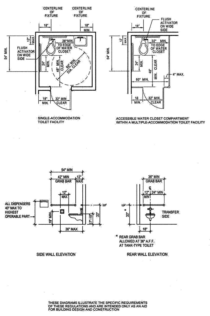
FIGURE 11B-1A
517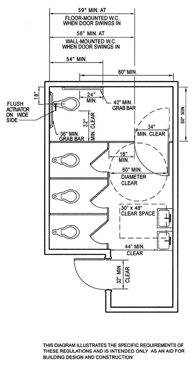
FIGURE 11B-1B—MULTIPLE-ACCOMMODATION TOILET FACILITY
518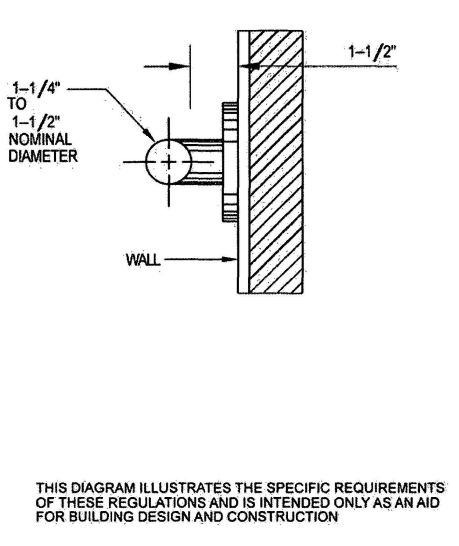
FIGURE 11B-1C—TYPICAL GRAB BAR SECTION
519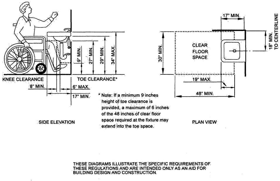
FIGURE 11 B-1 D—KNEE CLEARANCE
520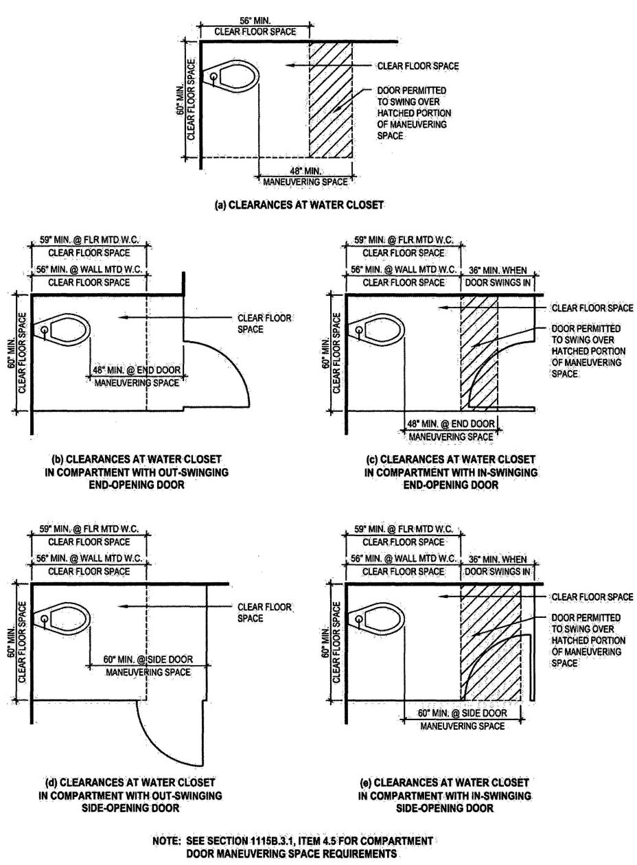
FIGURE 11B-1E—CLEARANCES AT WATER CLOSETS
521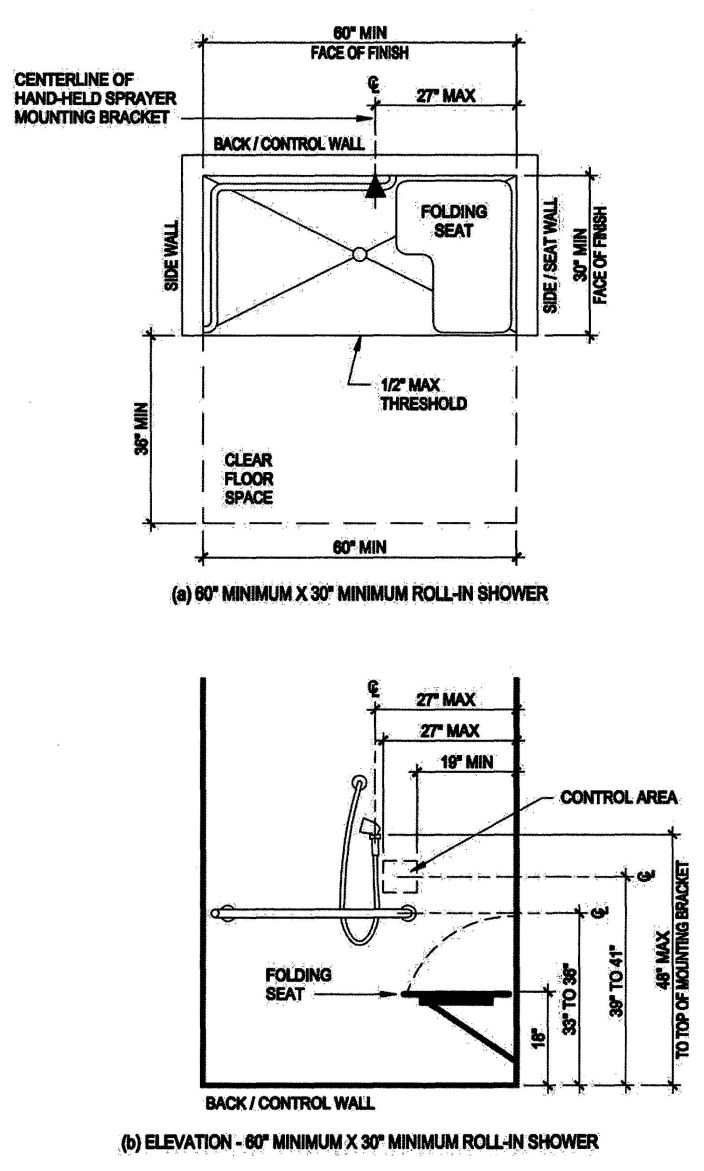
FIGURE 11B-2A—SHOWER STALLS (continued)
522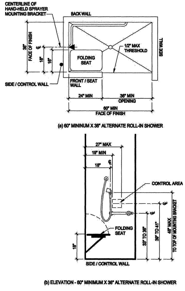
FIGURE 11B-2B—SHOWER STALLS—continued
523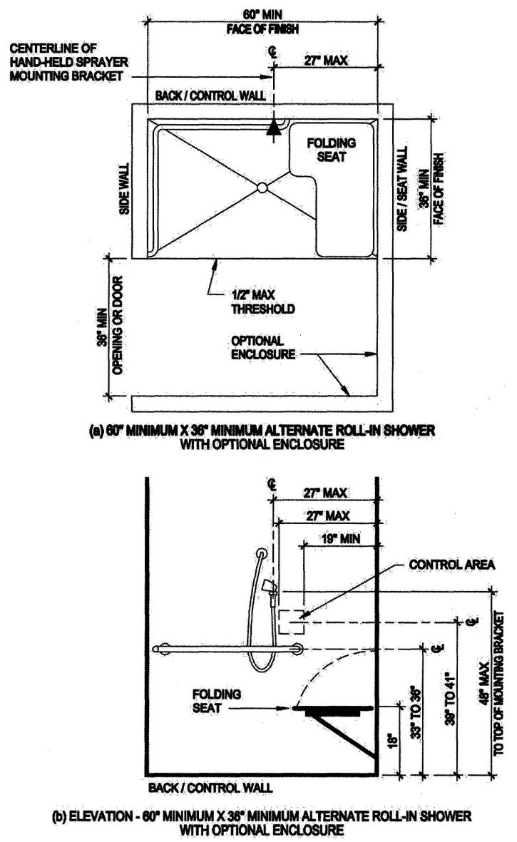
FIGURE 11B-2C—SHOWER STALLS—continued
524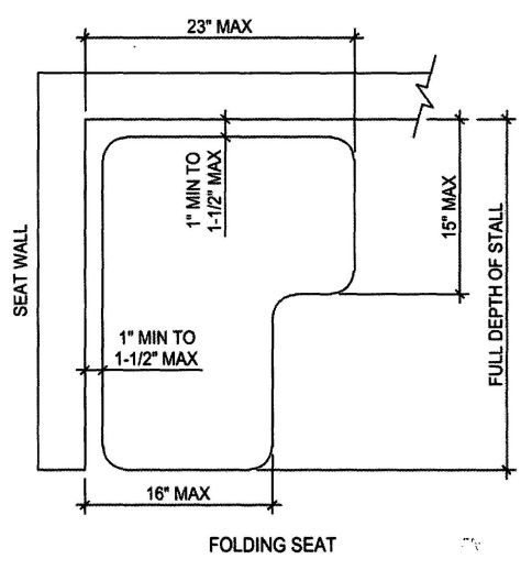
FIGURE 11B-2D—SHOWER SEAT
525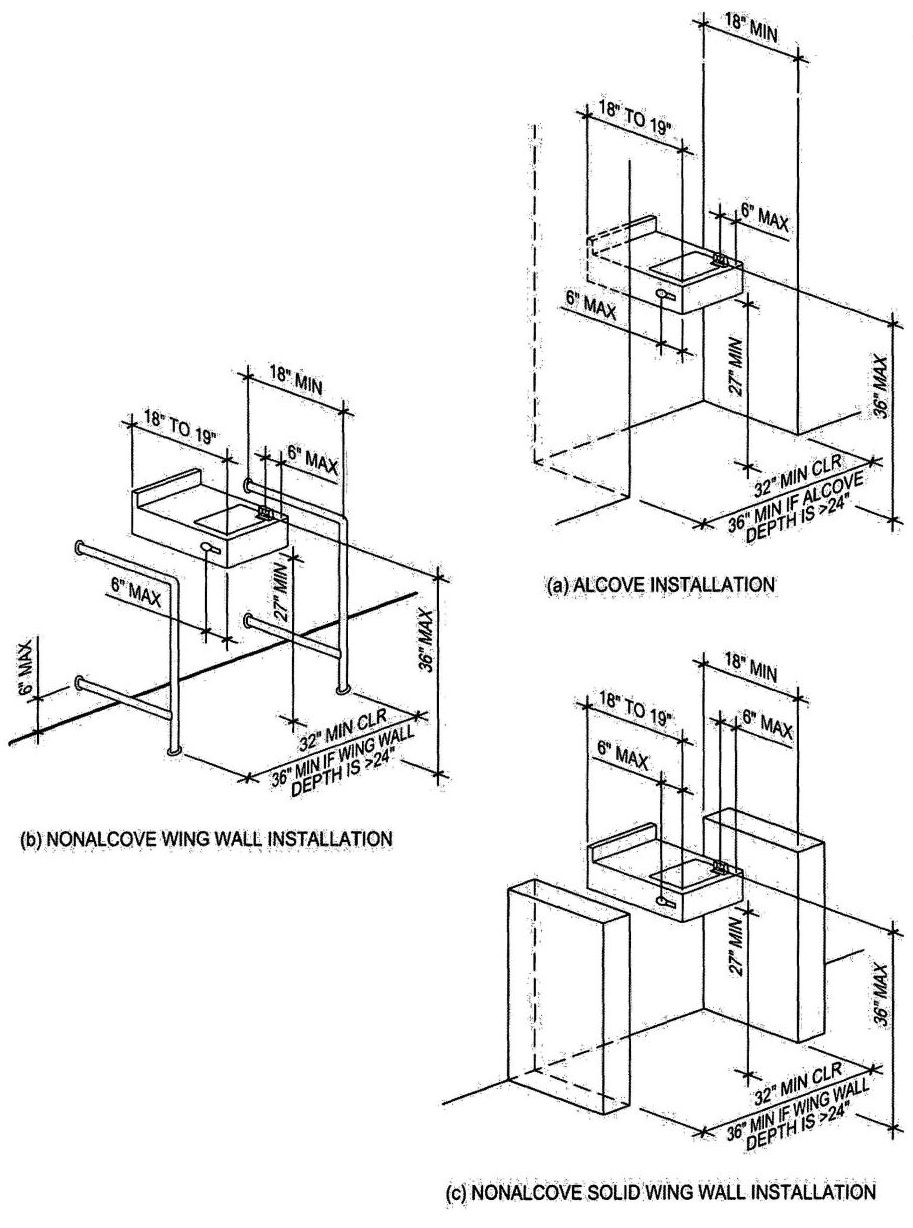
FIGURE 11B-3A—DRINKING FOUNTAINS
(continued)
526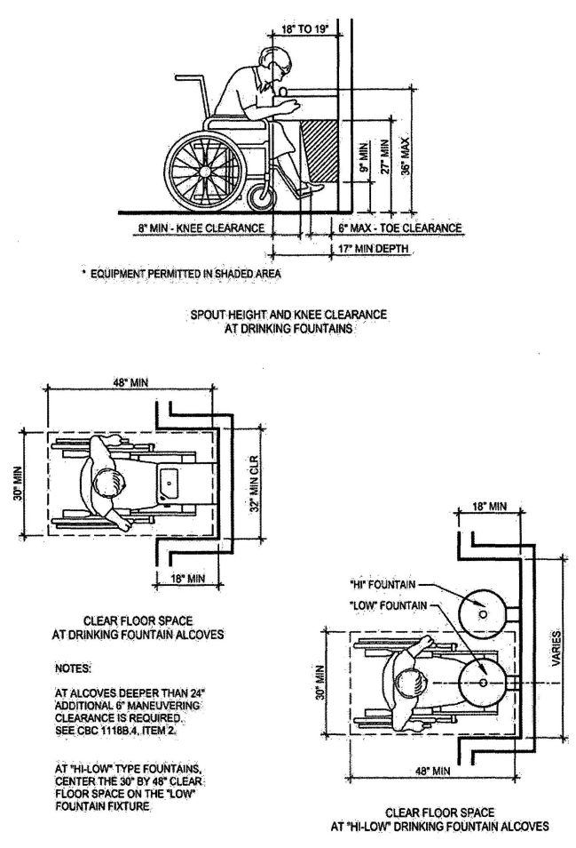
FIGURE 11B-3B—DRINKING FOUNTAINS—continued
527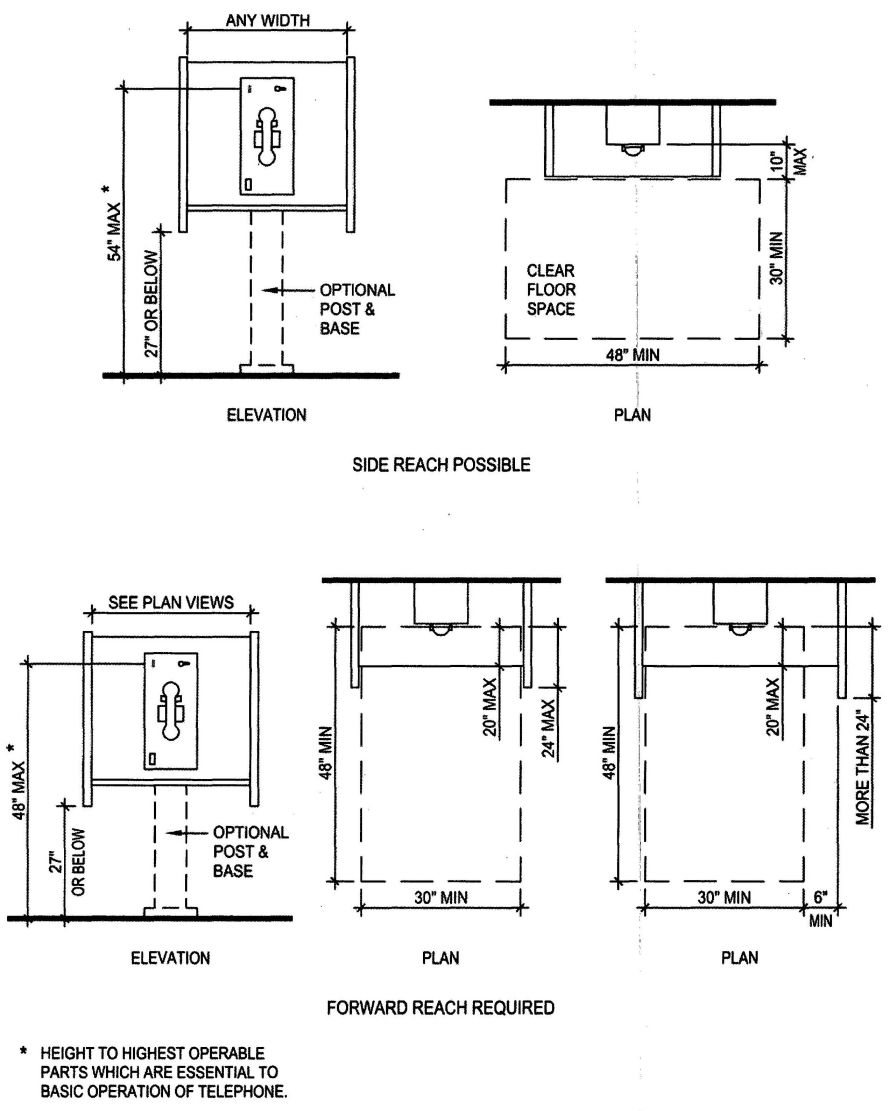
FIGURE 11B-4—MOUNTING HEIGHTS AND CLEARANCES FOR TELEPHONES
528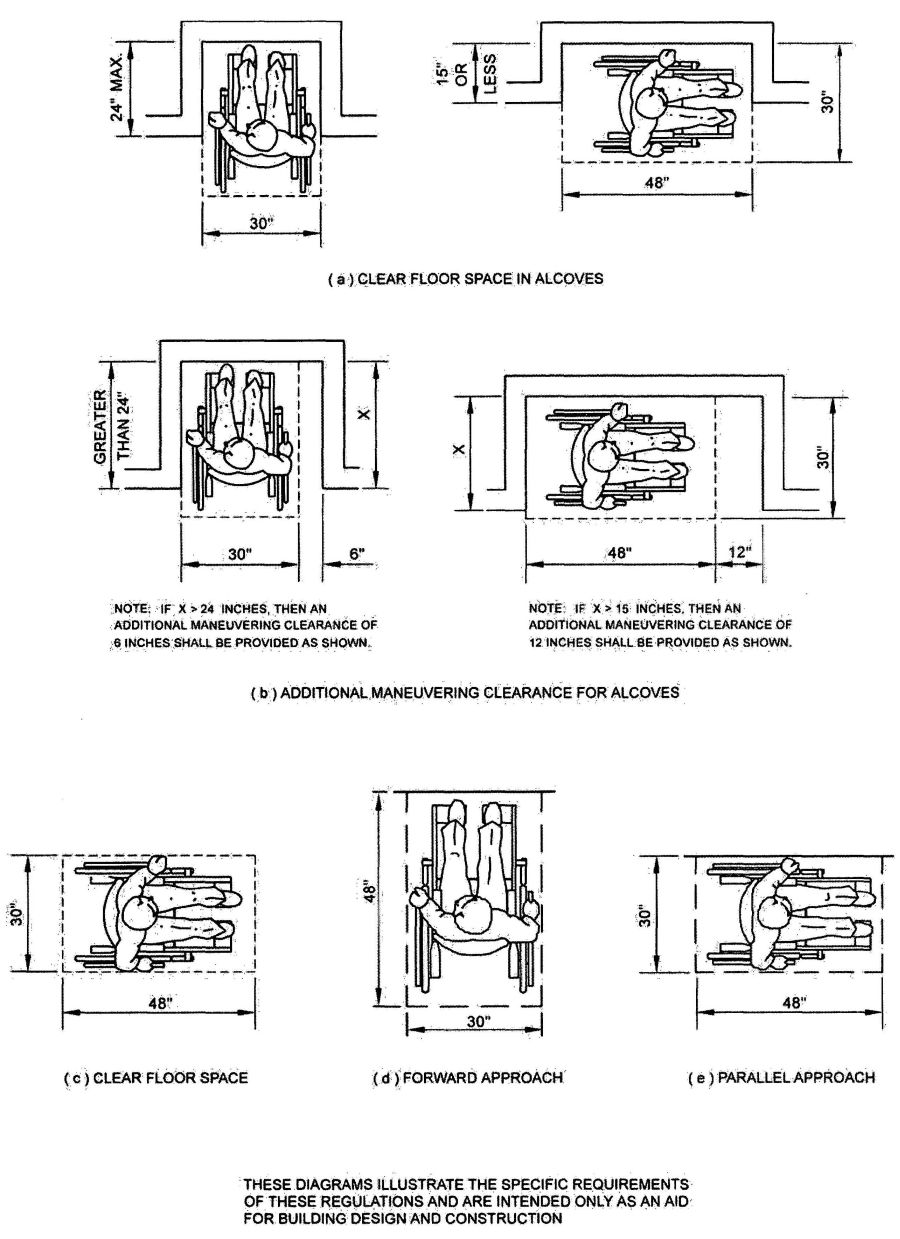
FIGURE 11B-5A—MINIMUM CLEAR FLOOR SPACE FOR WHEELCHAIRS
529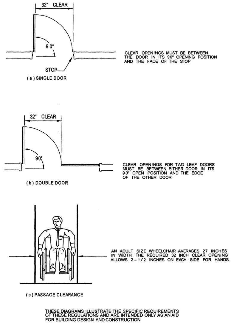
FIGURE 11B-5B—DOOR WIDTH
530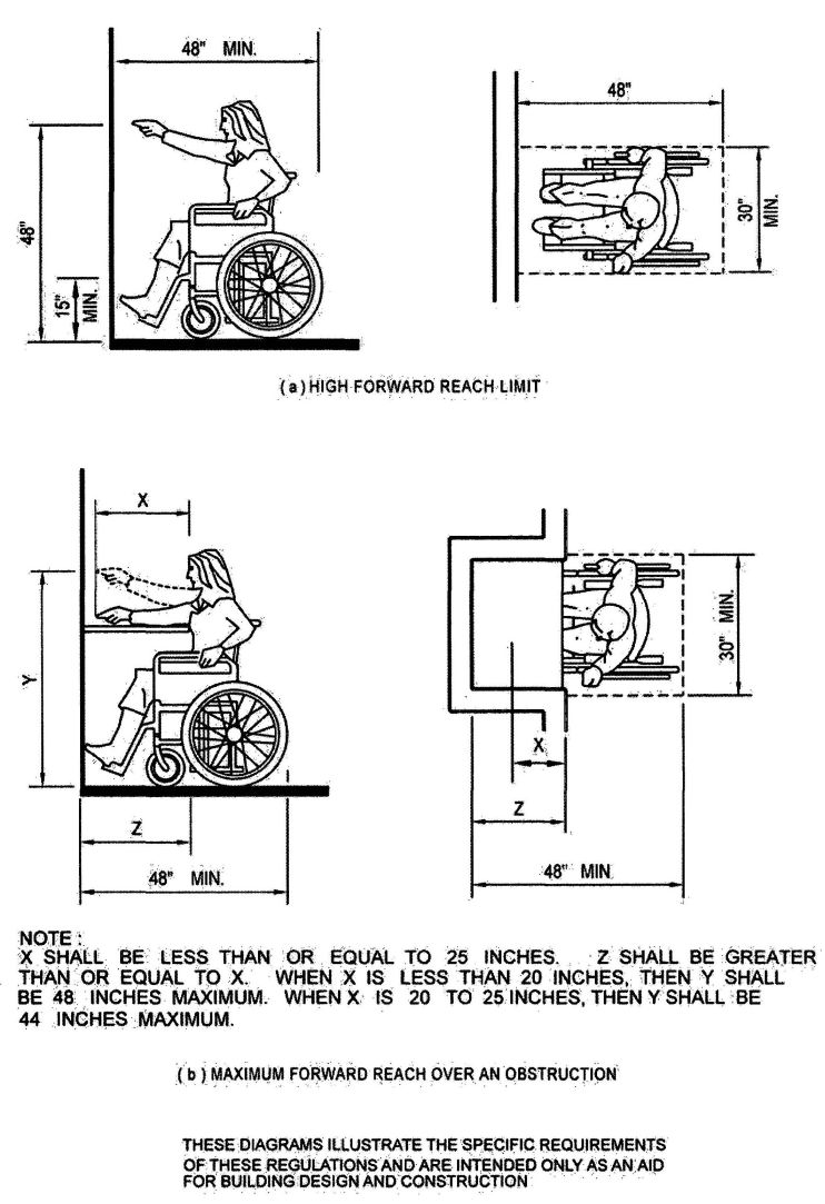
FIGURE 11B-5C—FORWARD REACH
531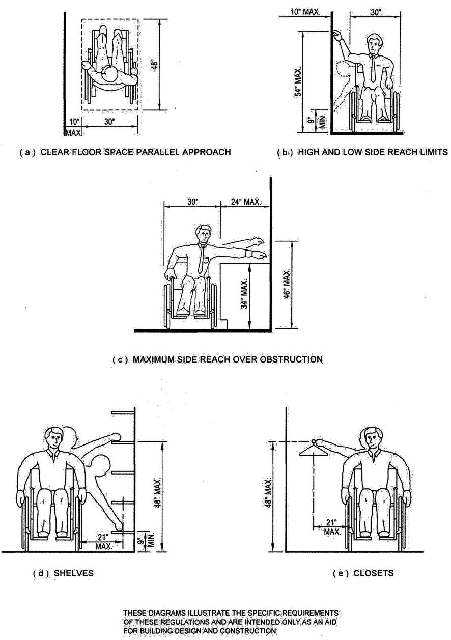
FIGURE 11B-5D—SIDE REACH
532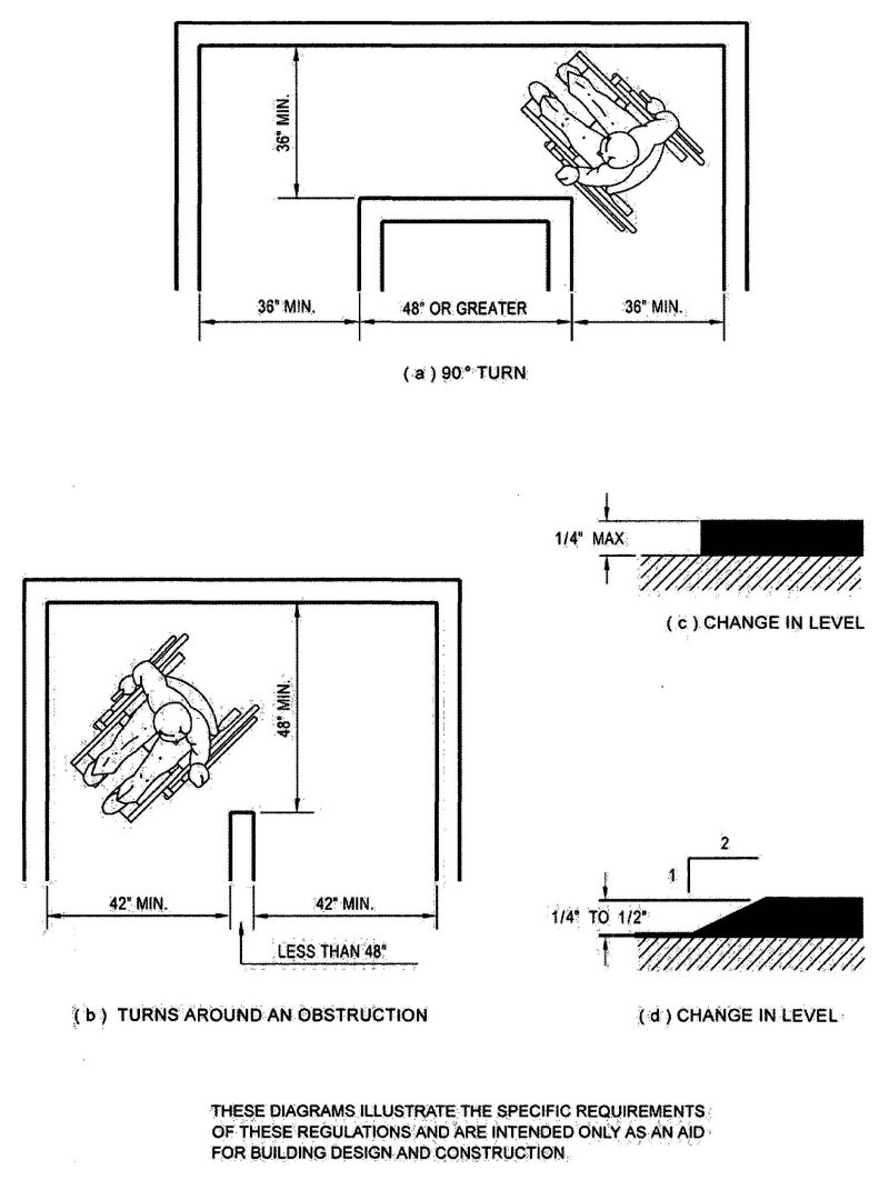
FIGURE 11B-5E—WIDTH OF ACCESSIBLE ROUTE
533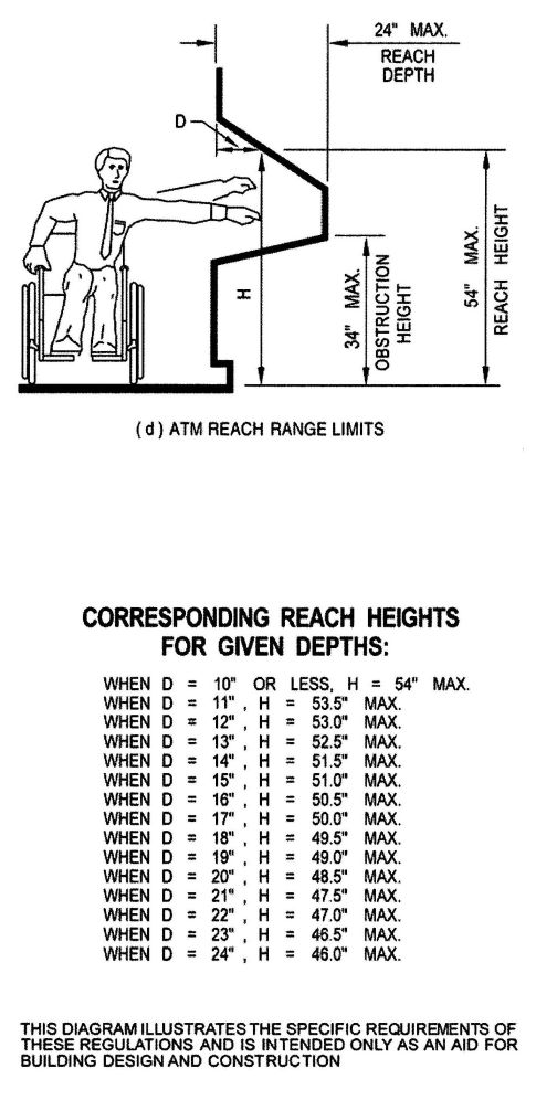
FIGURE 11B-5F—ATM REACH RANGE LIMITS
534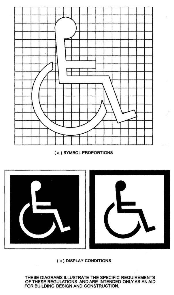
FIGURE 11B-6—INTERNATIONAL ACCESSIBILITY SYMBOL
535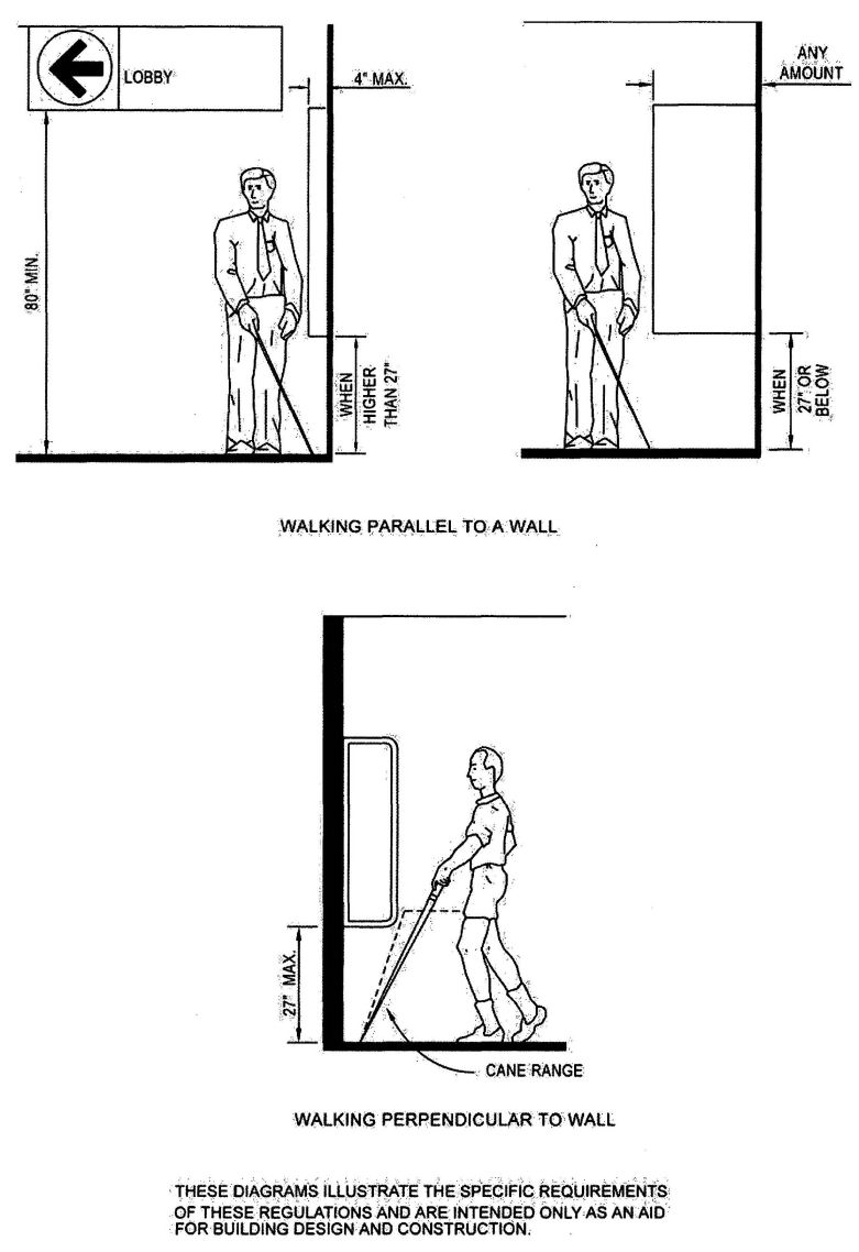
FIGURE 11B-7A—PROTRUDING OBJECTS
536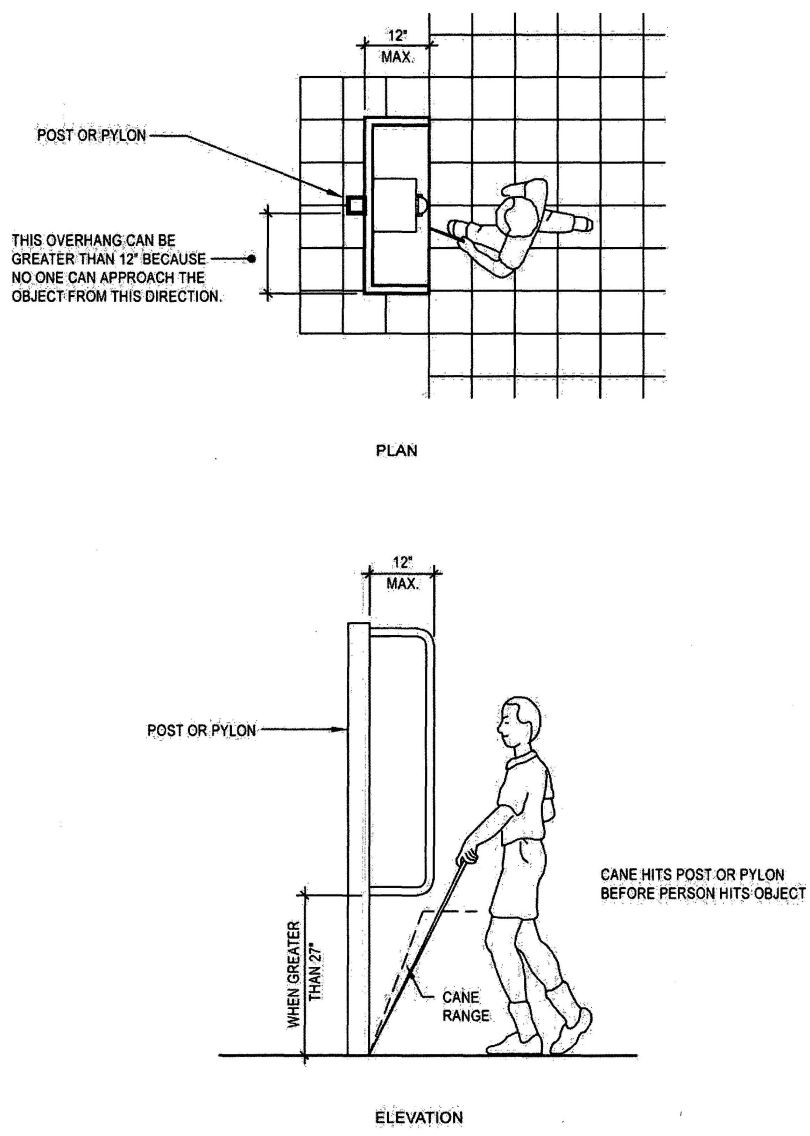
FIGURE 11B-7B—OBJECTS MOUNTED ON POSTS OR PYLONS
537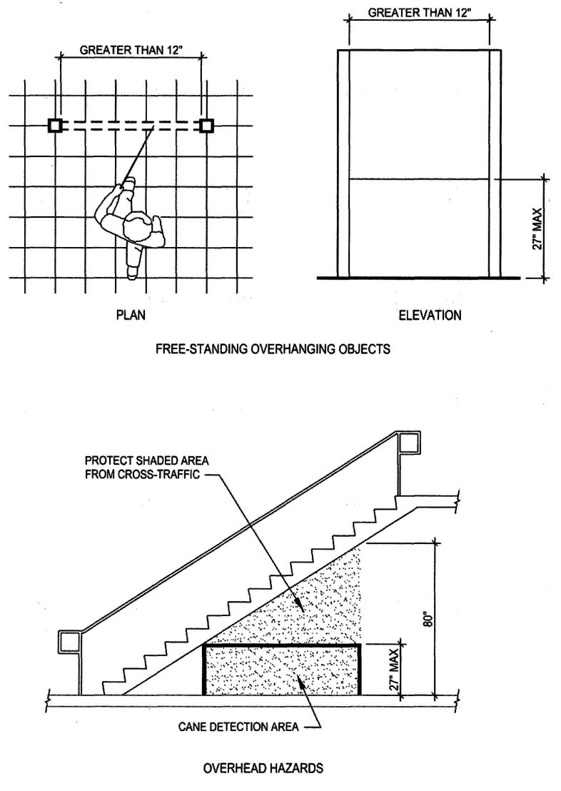
FIGURE 11B-7C—OVERHANGING AND OVERHEAD HAZARDS
538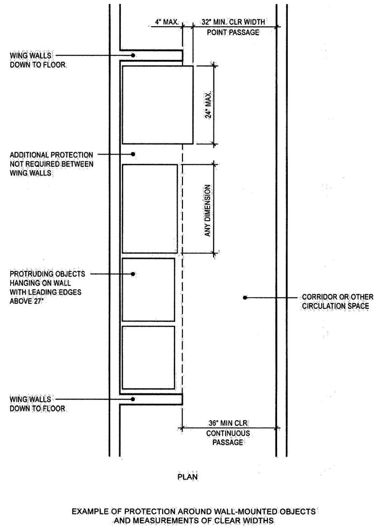
FIGURE 11B-7D—PROTECTION AROUND WALL-MOUNTED OBJECTS
539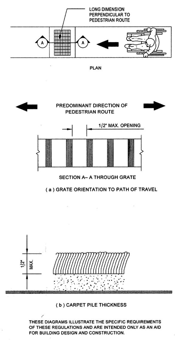
FIGURE 11B-7E
540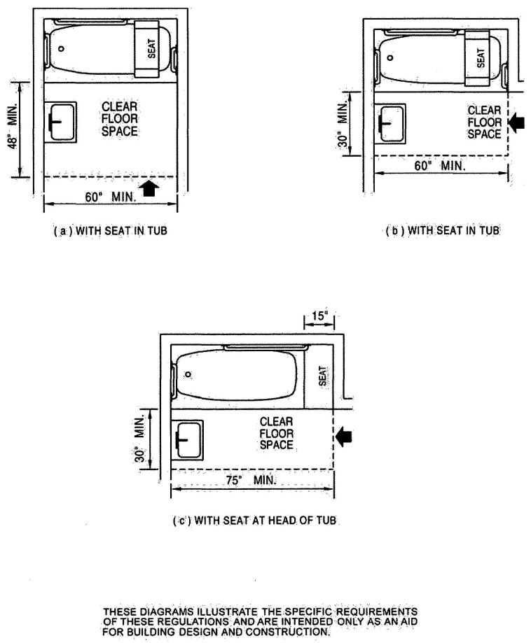
FIGURE 11B-8—CLEAR FLOOR SPACE AT BATHTUBS
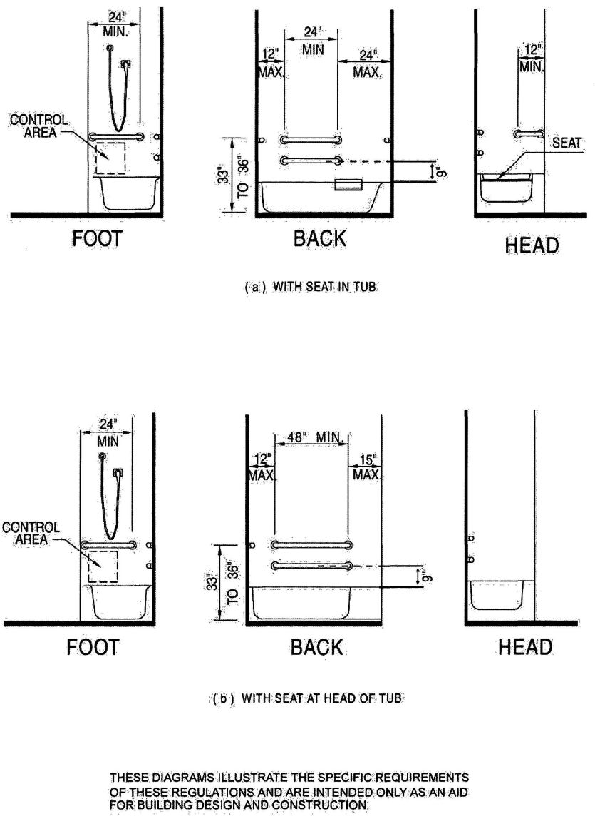
FIGURE 11B-9—GRAB BARS AT BATHTUBS
541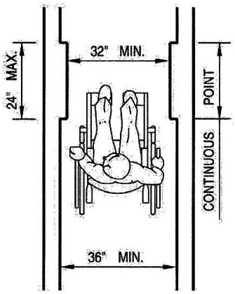
FIGURE 11B-10—MINIMUM CLEAR WIDTH FOR SINGLE WHEELCHAIR
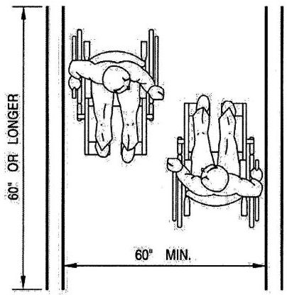
FIGURE 11B-11—MINIMUM CLEAR WIDTH FOR TWO WHEELCHAIRS
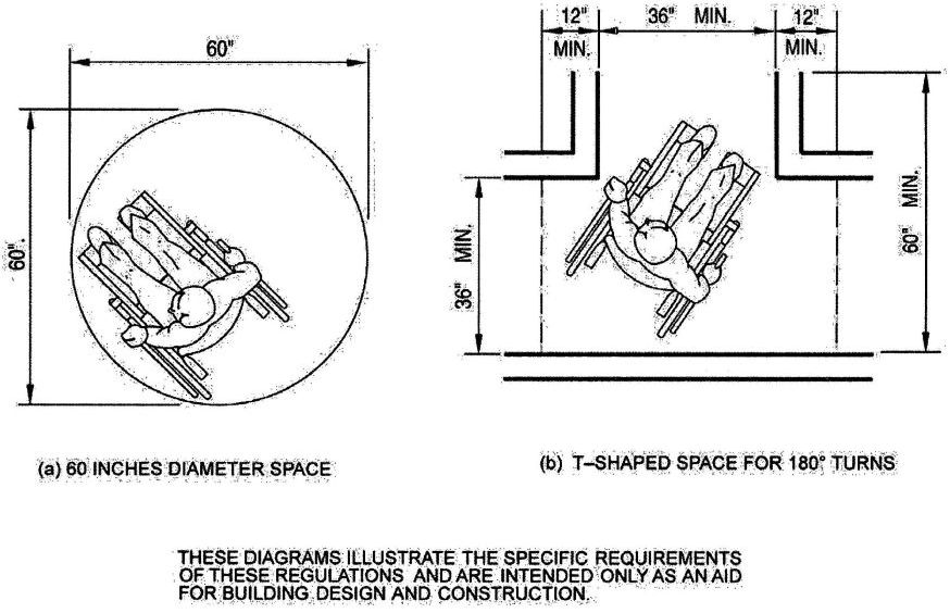
FIGURE 11B-12—WHEELCHAIR TURNING SPACE
543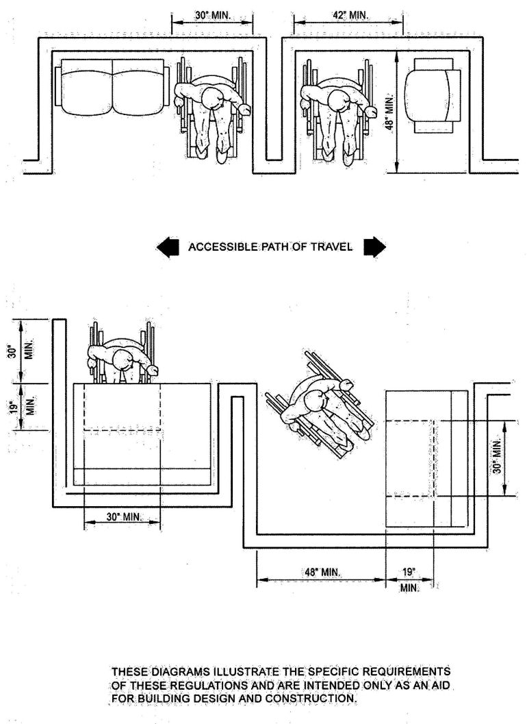
FIGURE 11B-13—MINIMUM CLEARANCES FOR SEATING AND TABLE
544
FIGURE 11B-14A—INTERNATIONAL TTY SYMBOL

FIGURE 11B-14B—VOLUME CONTROL TELEPHONES

FIGURE 11B-14C—INTERNATIONAL SYMBOL OF ACCESS FOR HEARING LOSS
THESE DIAGRAMS ILLUSTRATE THE SPECIFIC REQUIREMENTS OF THE THESE REGULATIONS AND ARE INTENDED ONLY AS AN AID FOR BUILDING DESIGN AND CONSTRUCTION
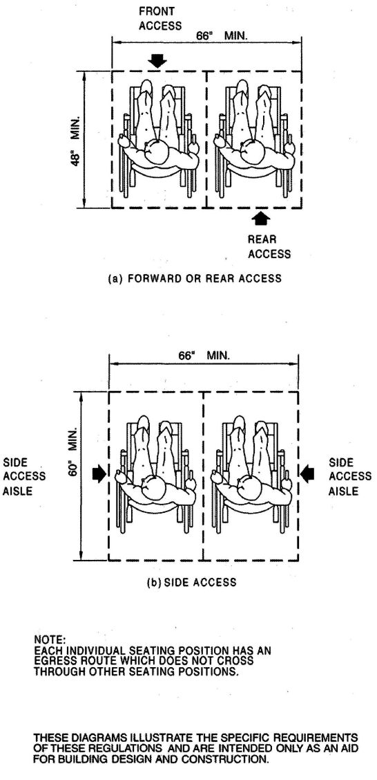
FIGURE 11B-15—SPACE REQUIREMENTS FOR WHEELCHAIR SEATING
546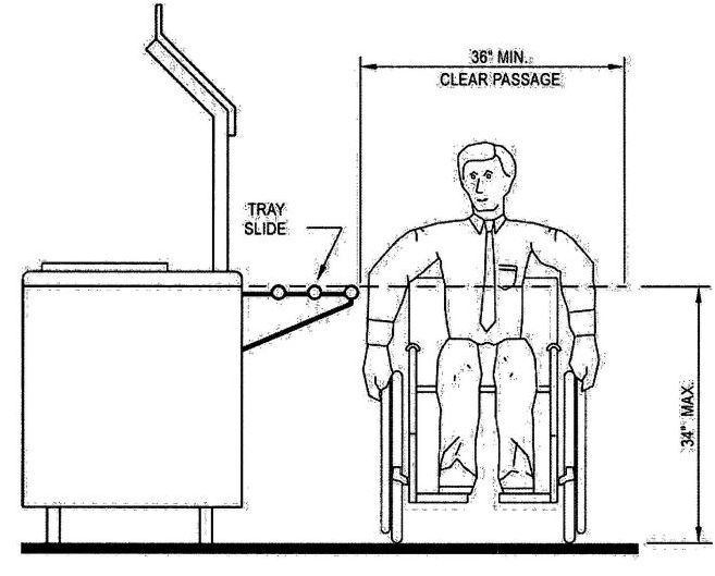
FIGURE 11B-16—FOOD SERVICE LINES
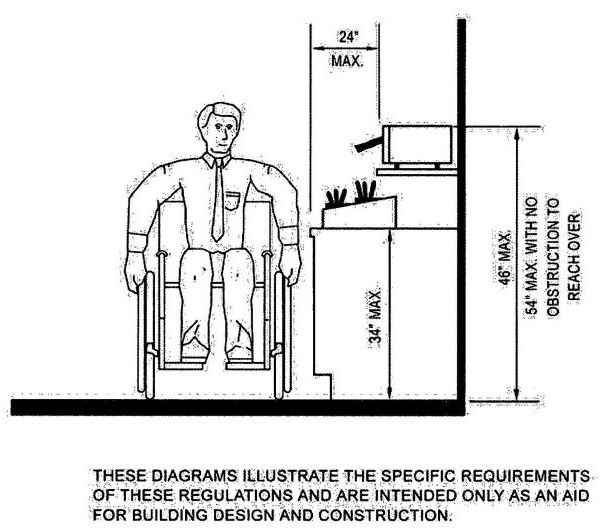
FIGURE 11B-17—TABLEWARE AREAS
547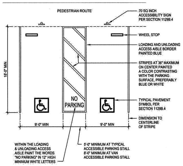
FIGURE 11B-18A—DOUBLE PARKING STALLS
548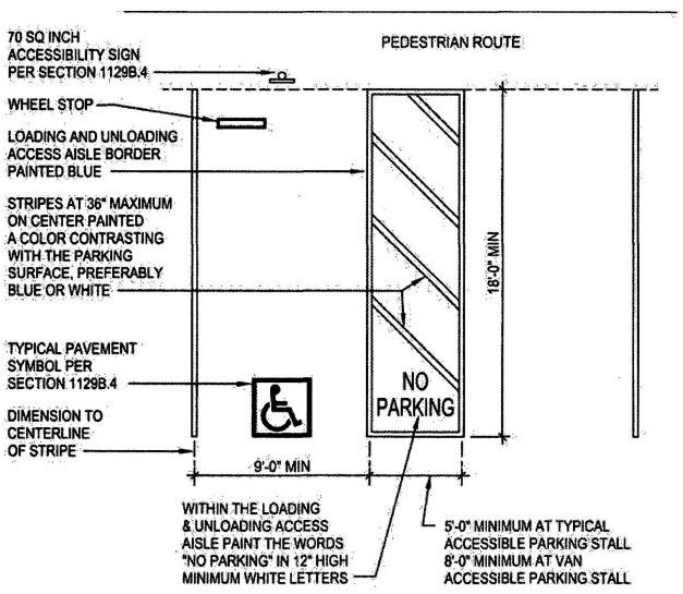
FIGURE 11B-18B—SINGLE PARKING STALLS
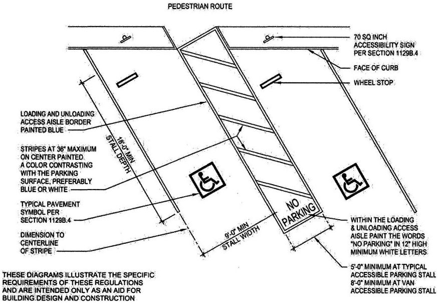
FIGURE 11B-18C—DIAGONAL PARKING STALLS
549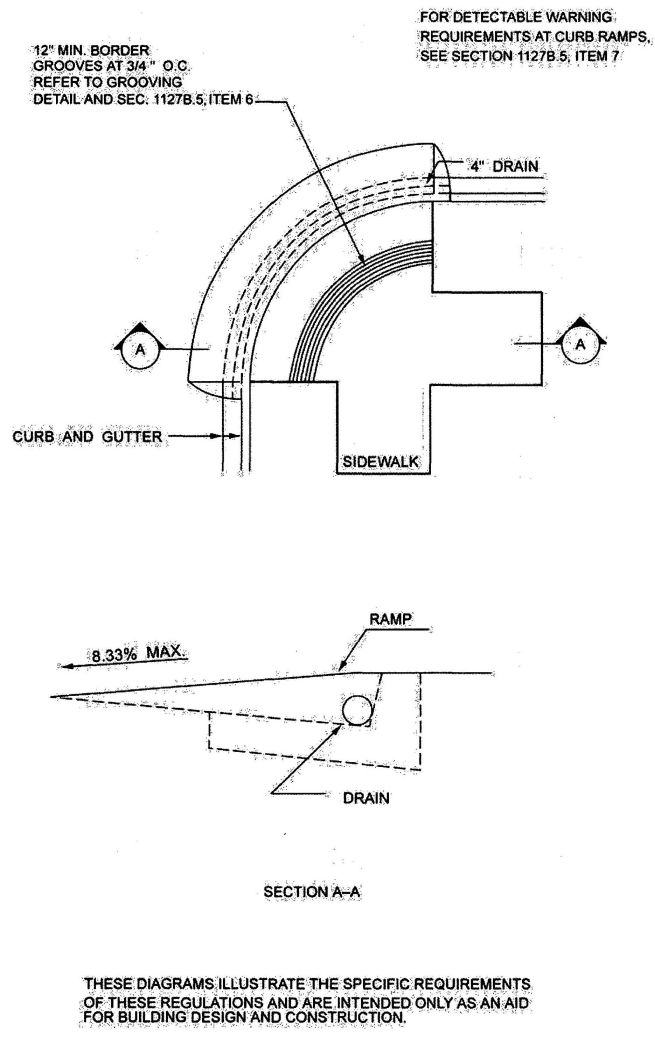
FIGURE 11B-19A—CURB DETAILS
550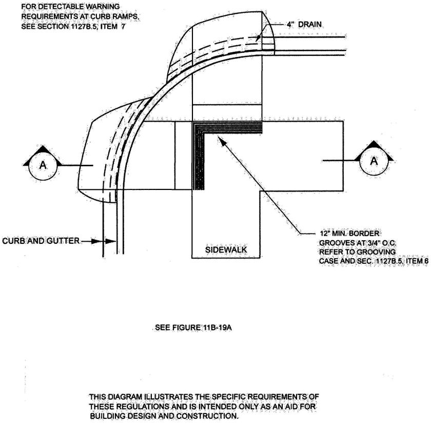
FIGURE 11B-19B—CURB DETAIL
551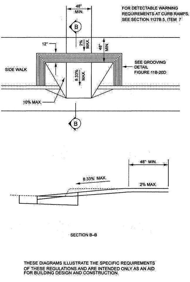
FIGURE 11B-19C—CURB DETAIL
552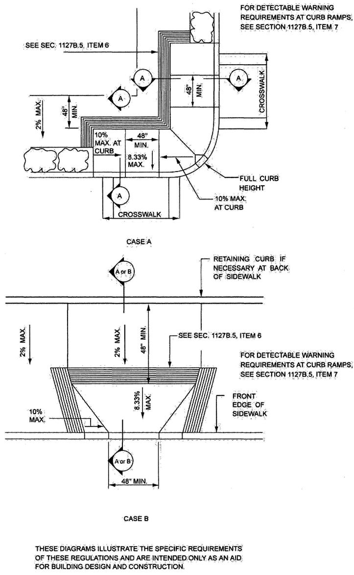
FIGURE 11B-20A—CURB DETAIL—CASES A AND B
553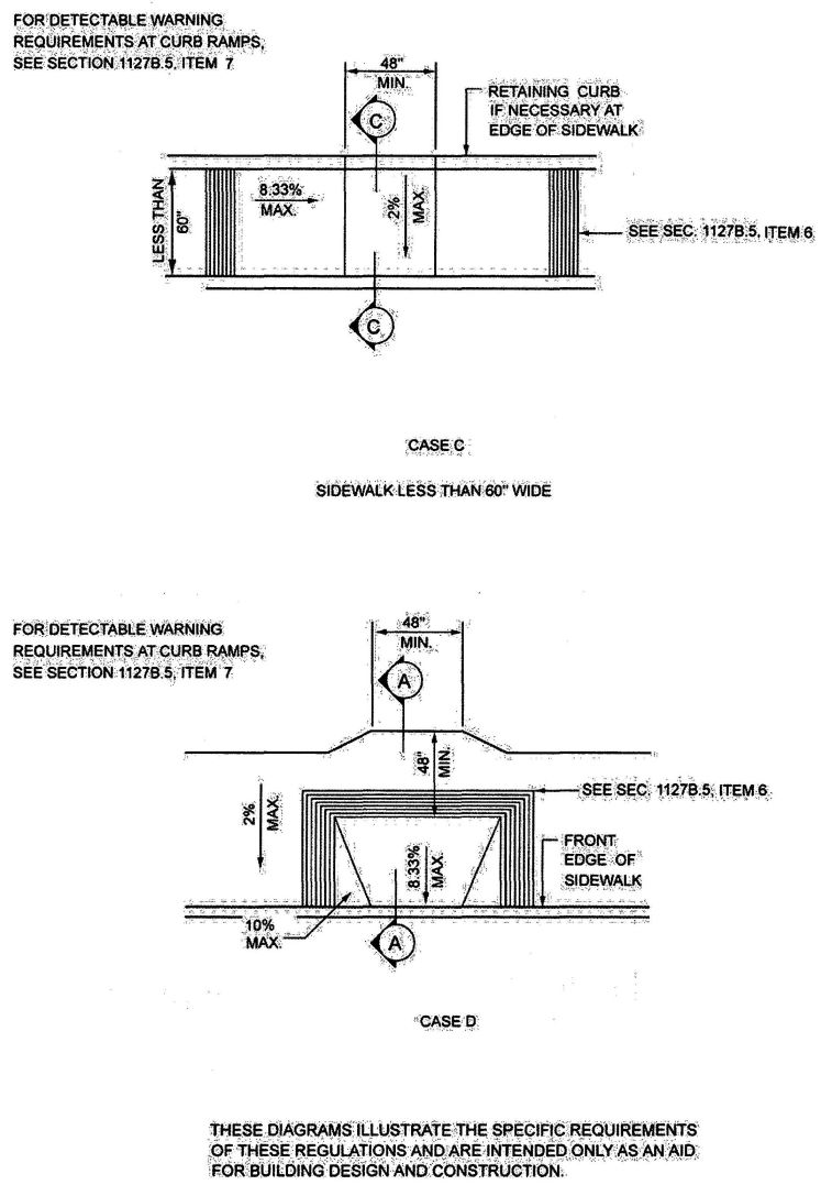
FIGURE 11B-20B—CURB DETAIL—CASES C AND D
554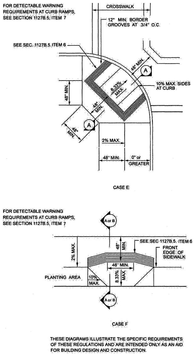
FIGURE 11B-20C—CURB DETAIL—CASES E AND F
555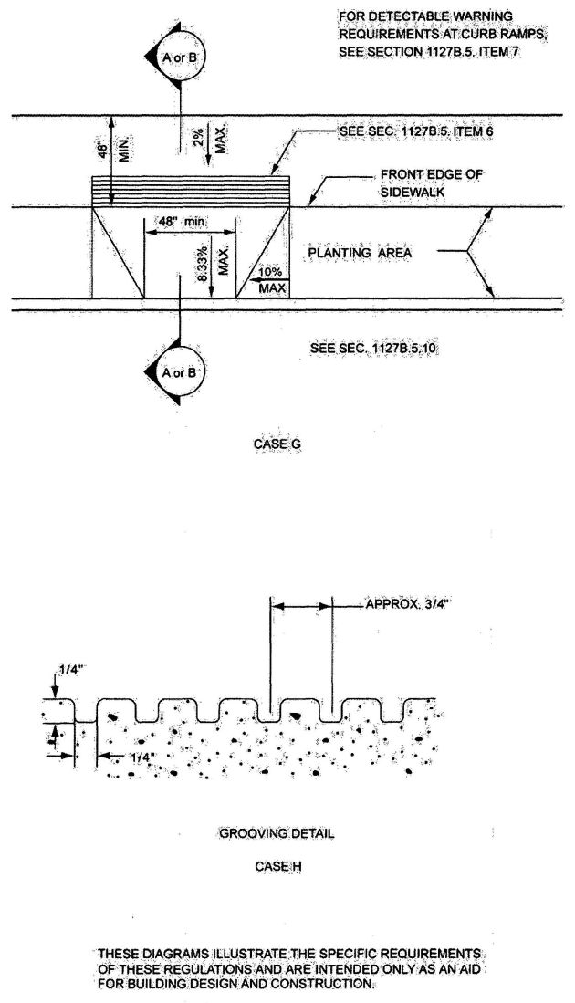
FIGURE 11B-20D—CURB DETAIL—CASES G AND H"
556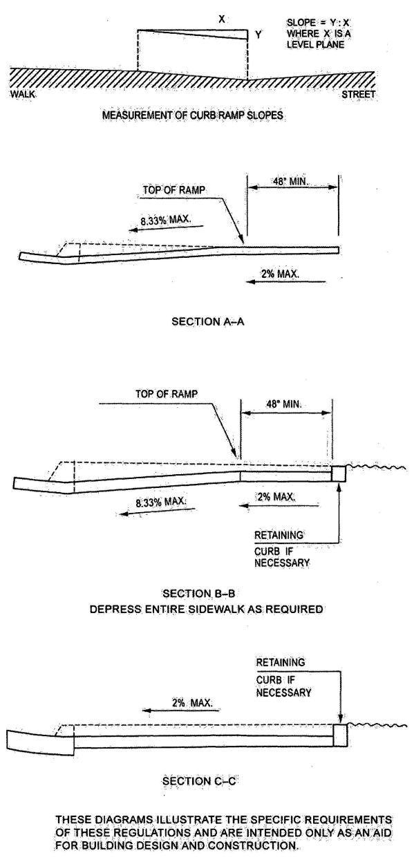
FIGURE 11B-20E—CURB SECTIONS
557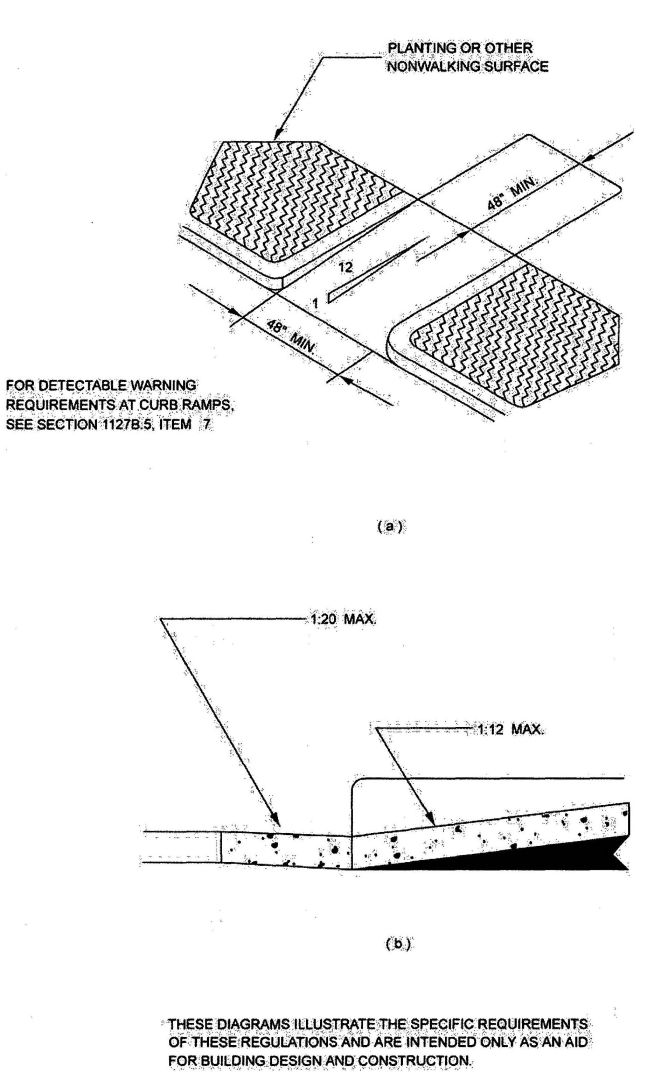
FIGURE 11B-21—RETURNED CURB STYLE
558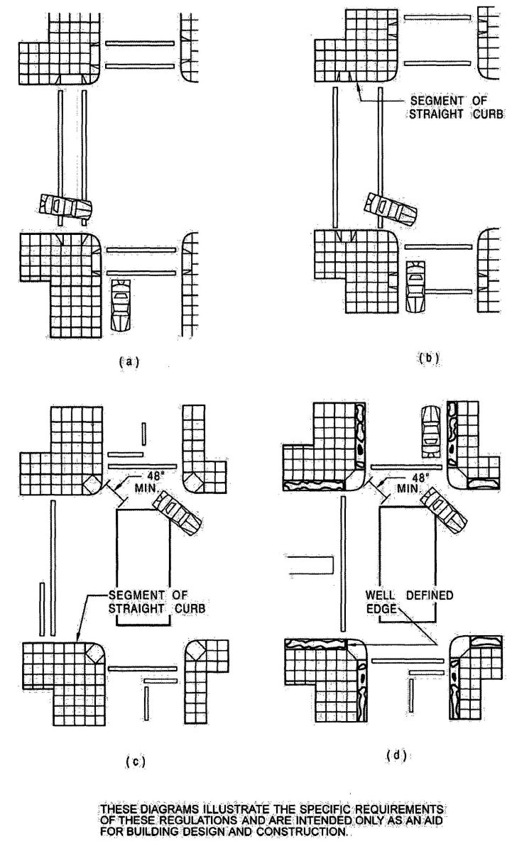
FIGURE 11B-22—CURB RAMPS AT MARKED CROSSING"
559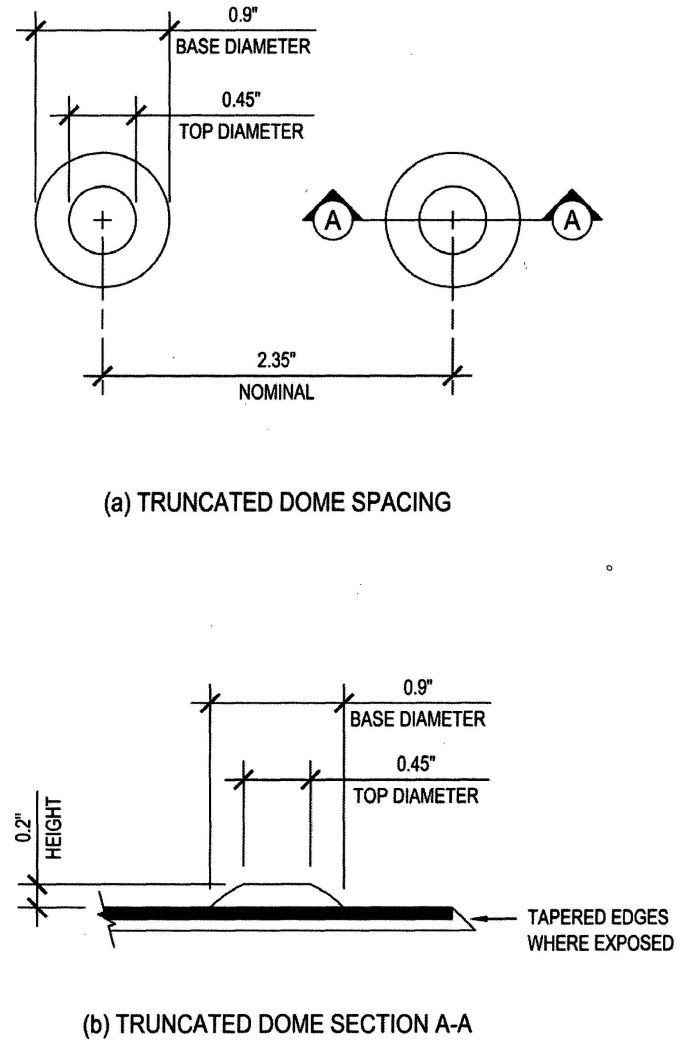
FIGURE 11B-23A—TRUNCATED DOMES
560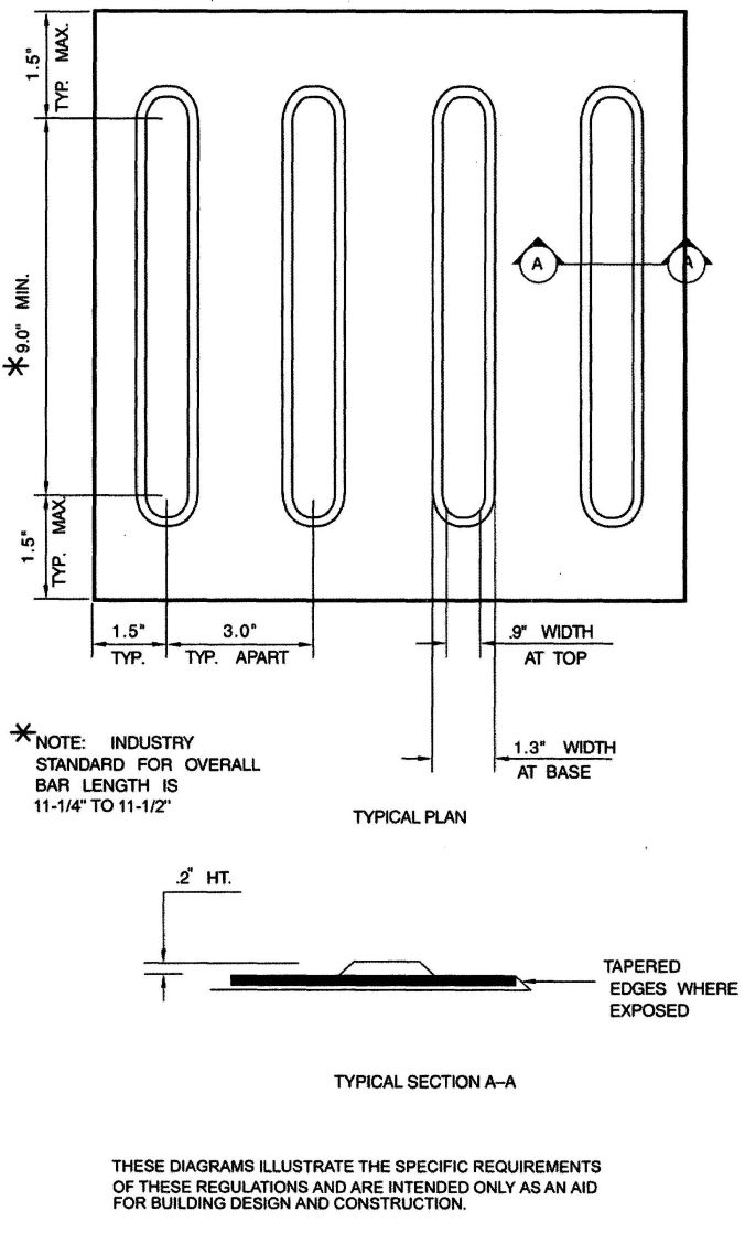
FIGURE 11B-23B—DIRECTIONAL BARS
561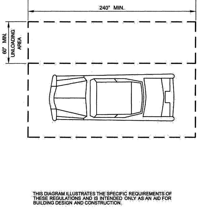
FIGURE 11B-24—ACCESS AISLE AT PASSENGER LOADING ZONES
562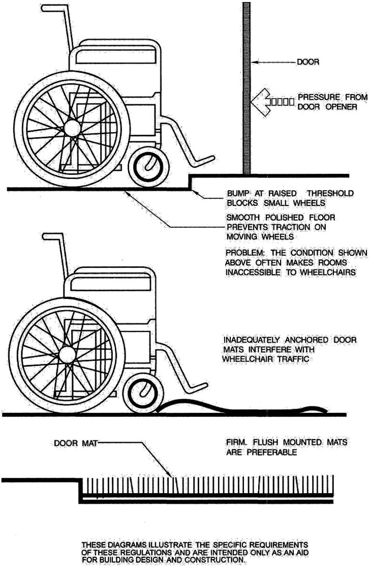
FIGURE 11B-25—OBSTRUCTIONS
563
FIGURE 11B-26A—LEVEL MANEUVERING CLEARANCE AT DOORS
(continued)
564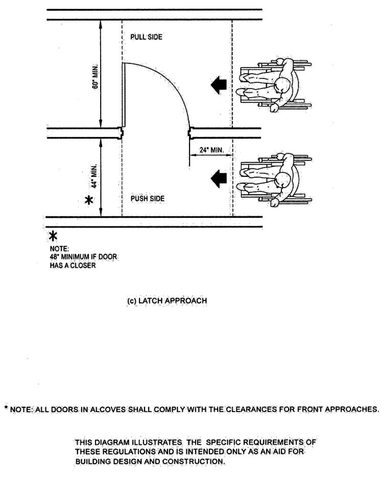
FIGURE 11B-26B—LEVEL MANEUVERING CLEARANCE AT DOORS—continued
(continued)
565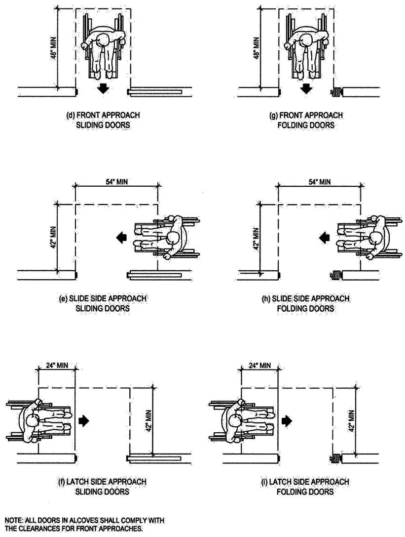
FIGURE 11B-26C—LEVEL MANEUVERING CLEARANCE AT DOORS—continued
(continued)
566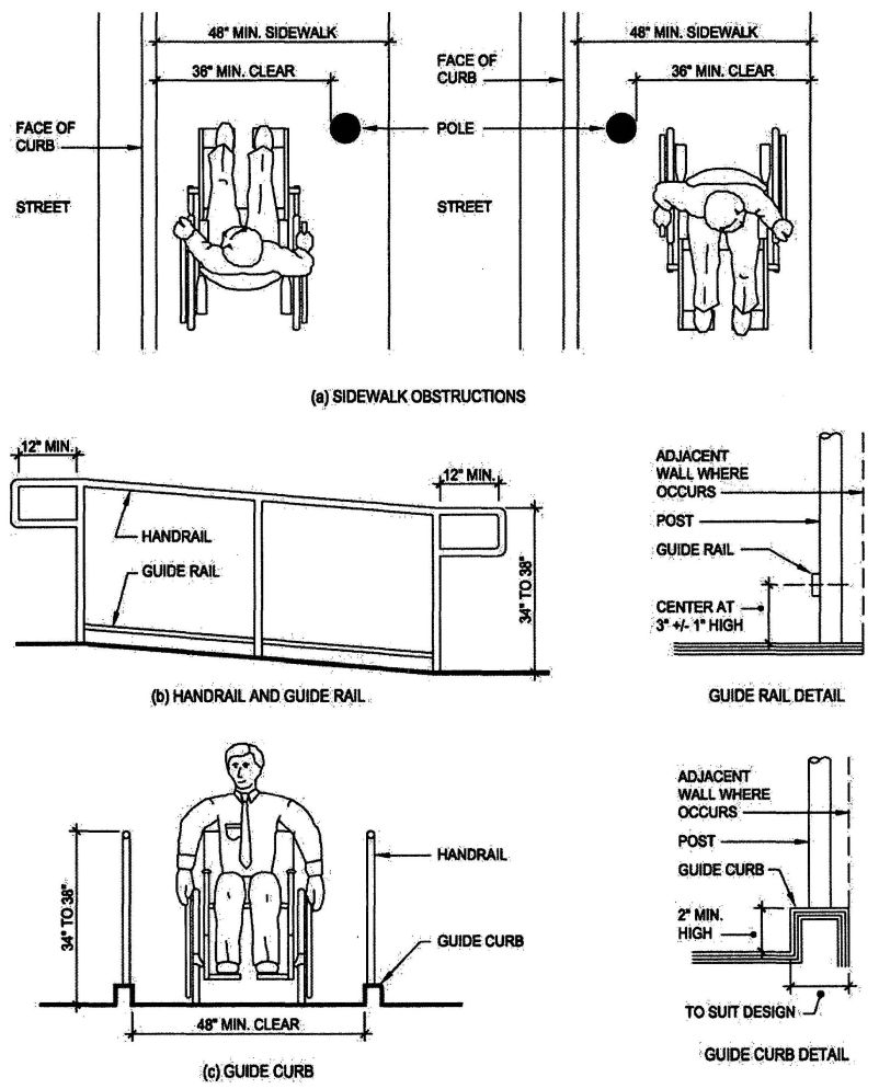
FIGURE 11B-27—RAMPS AND SIDEWALKS
567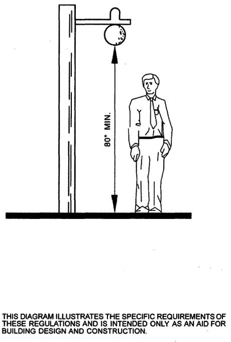
FIGURE 11B-28—OVERHANGING OBSTRUCTION
568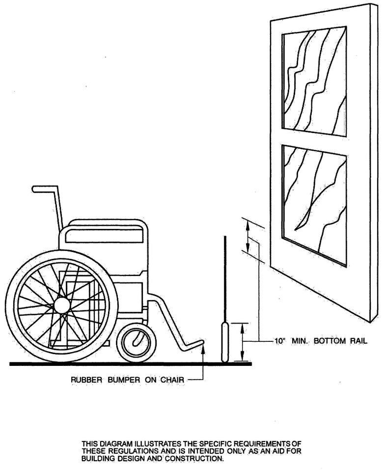
FIGURE 11B-29—DOOR CONSTRUCTION
569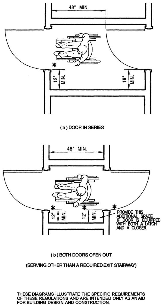
FIGURE 11 B-30—VESTIBULE
570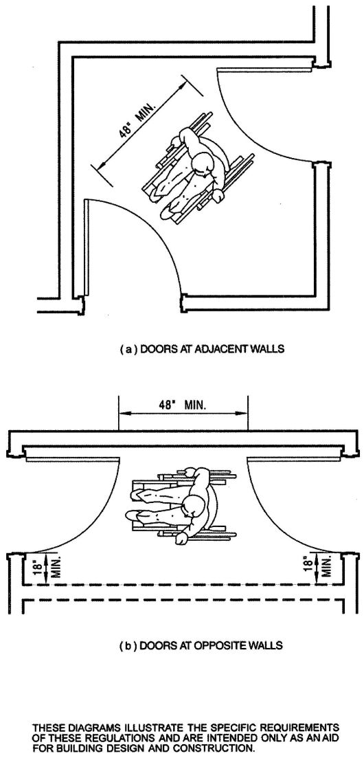
FIGURE 11B-31—VESTIBULE (SERVING OTHER THAN REQUIRED EXIT STAIRWAY)
571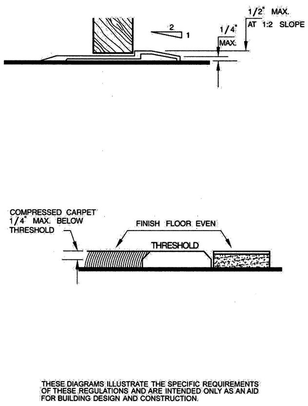
FIGURE 11B-32—THRESHOLDS
572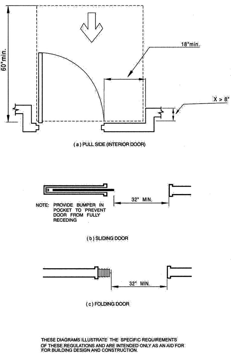
FIGURE 11B-33—CLEAR DOOR WIDTH AND DEPTH
573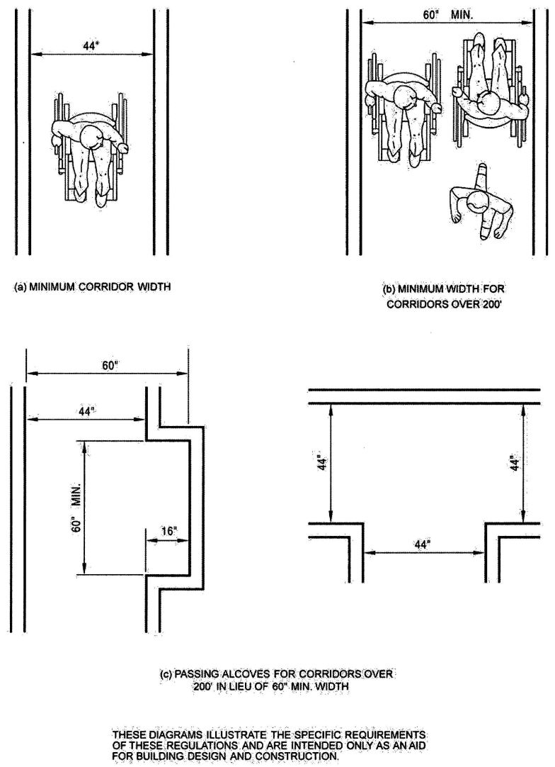
FIGURE 11B-34—CORRIDOR OVER 200 FEET (60 960 mm)
574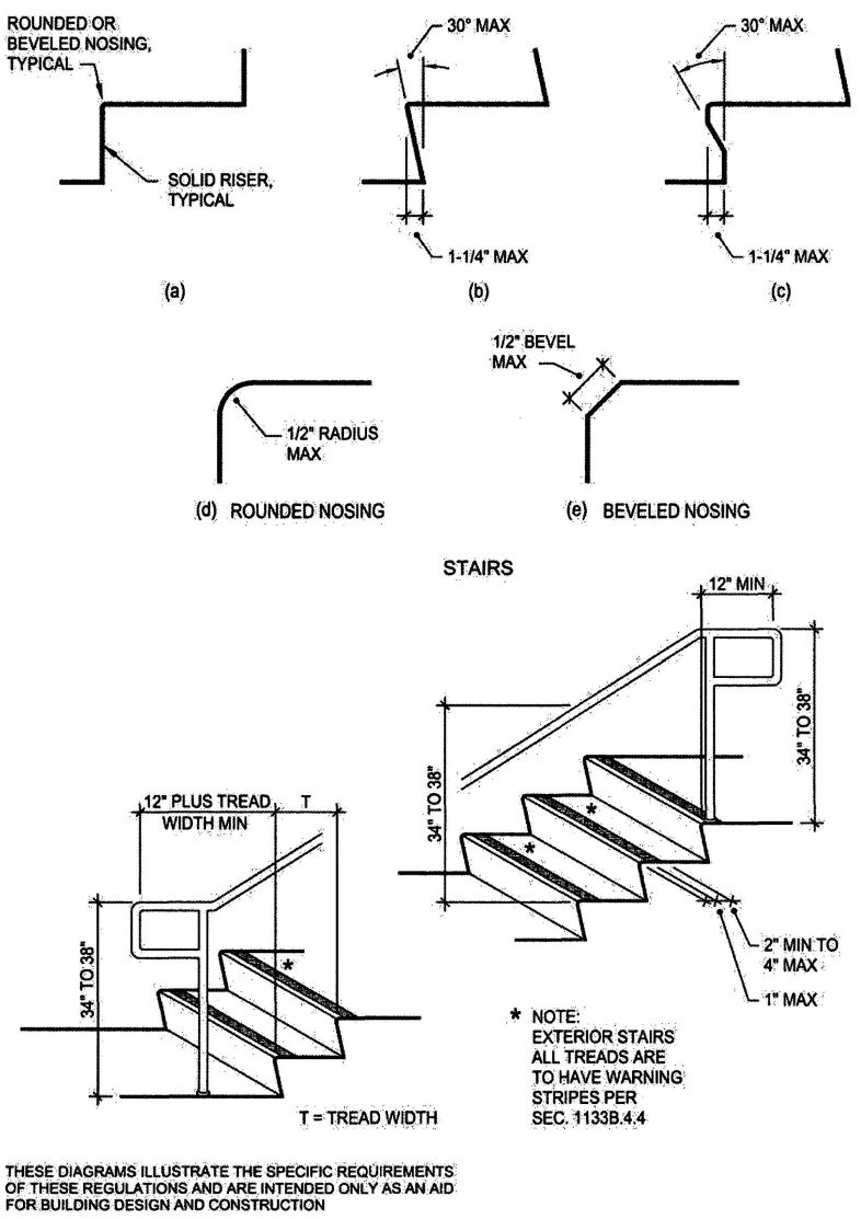
FIGURE 11B-35—WARNING STRIPING AND HANDRAIL EXTENSIONS
575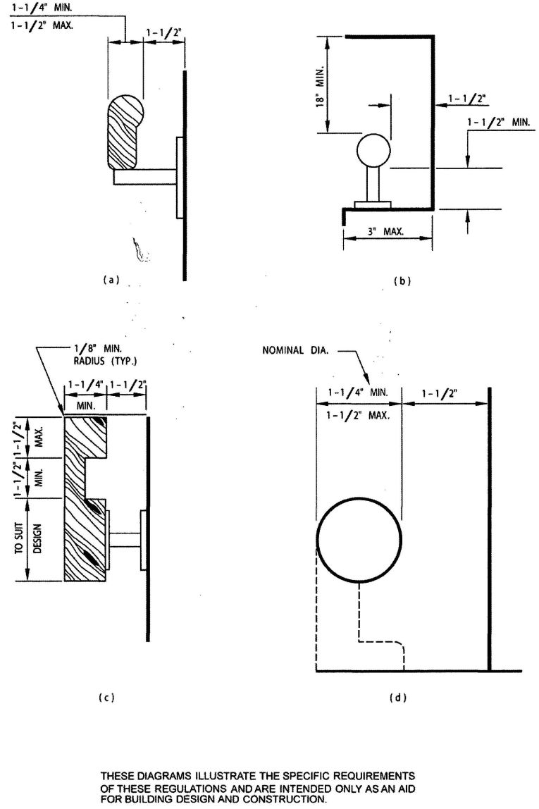
FIGURE 11B-36—STAIR HANDRAILS
576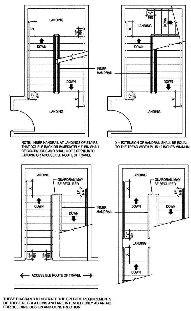
FIGURE 11B-37—STAIR HANDRAILS
577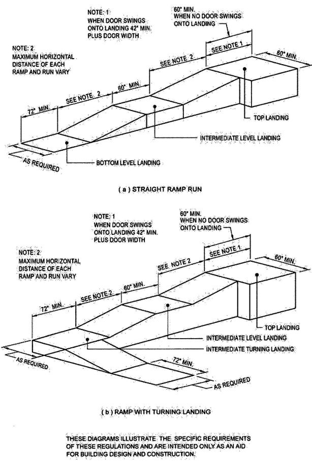
FIGURE 11B-38—RAMP DIMENSIONS
578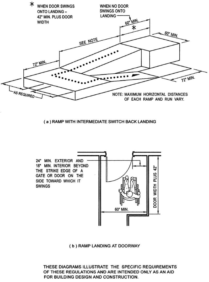
FIGURE 11B-39—RAMP LANDING AND DOORWAY
579
FIGURE 11B-40—CLEANER AIR SYMBOL
580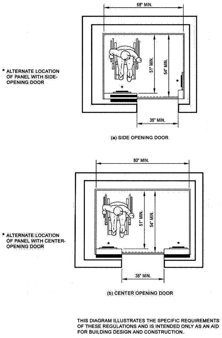
FIGURE 11B-40A—MINIMUM DIMENSIONS OF ELEVATOR CARS
581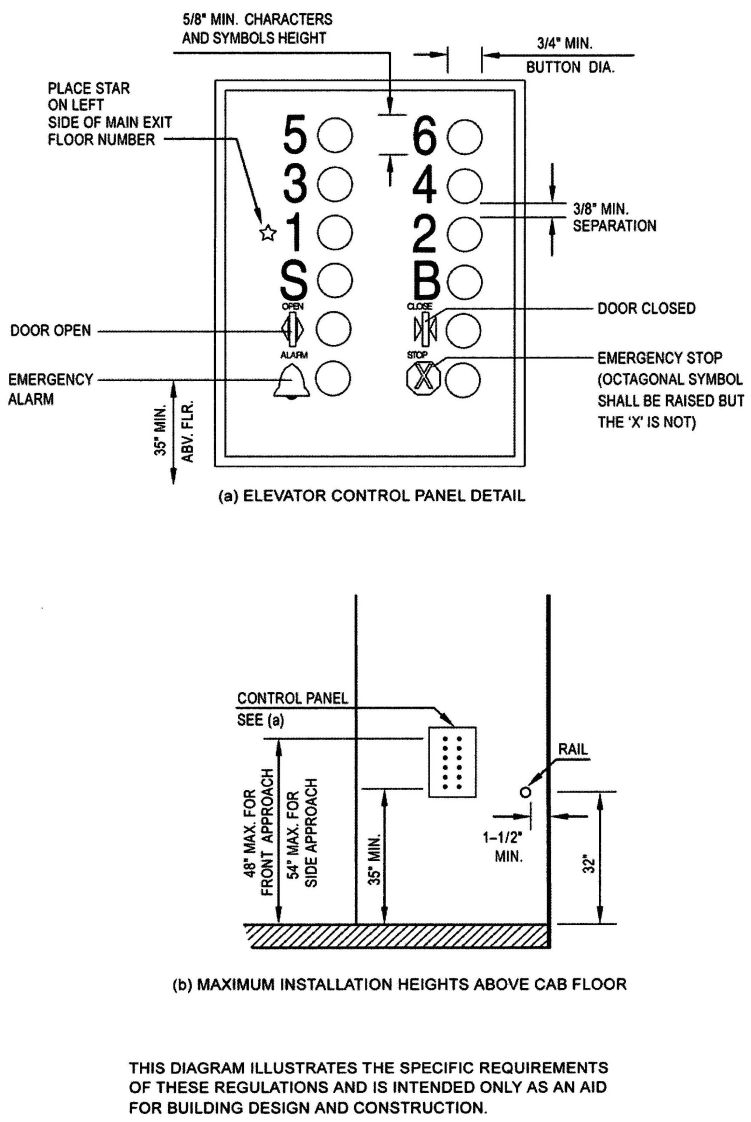
FIGURE 11B-40B—ELEVATOR CONTROL PANEL
582
FIGURE 11B-40C—HOISTWAY AND ELEVATOR ENTRANCES
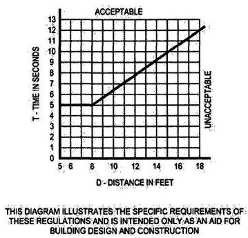
FIGURE 11B-40D—GRAPH OF TIMING EQUATION
583 584| Adopting agency | BSC | SFM | HCD | DSA | OSHPD | CSA | DPH | AGR | DWR | CEC | CA | SL | SLC | |||||||
|---|---|---|---|---|---|---|---|---|---|---|---|---|---|---|---|---|---|---|---|---|
| 1 | 2 | 1-AC | AC | SS | SS/CC | 1 | 2 | 3 | 4 | |||||||||||
| Adopt entire chapter | X | |||||||||||||||||||
| Adopt entire chapter as amended (amended sections listed below) | ||||||||||||||||||||
| Adopt only those sections that are listed below | ||||||||||||||||||||
| Chapter/Section | ||||||||||||||||||||
1101C.1 General. Notwithstanding other requirements in the California Building Code, only the requirements and additional definitions in this section shall apply to card-reading devices in motor vehicle fuel facilities, except that administrative requirements which are found in Chapter 1—California Administration Division I still apply.
For purposes of this section, the following definitions shall apply:
ACCESSIBLE. See Chapter 11A, Section 1107A.1-A and Chapter 11B, Section 1102B.
ACCESSIBLE ELEMENT. See Chapter 11B, Section 1102B.
ALTERNATE CARD READER shall be defined in this section as functionally equal card reader and control directly attached to or an integral part of the fuel dispenser in addition to the primary card reader, which is an integral part of the dispenser.
FREE-STANDING PEDESTAL is a card-reading device which controls one or more remote fuel dispensers that have no card readers as an integral part of the fuel dispenser.
GRADE (Adjacent Ground Elevation). See Chapter 2, Section 202.
INTERNATIONAL SYMBOL OF ACCESSIBILITY. See Chapter 11A, Section 1107A.9-I and Chapter 11B, Section 1102B.
LEVEL ACCESSIBLE AREA, for the purpose of this section, shall mean a slope of not more than one unit vertical in 50 units horizontal (2-percent slope) in front of the dispensing device; however, the slope may extend to one unit vertical in 20 units horizontal (5-percent slope) where the enforcing authority determines that, due to unusual site conditions, the 2-percent slope is not obtainable.
LEVEL AREA. See Chapter 11A, Section 1107A.12-L and Chapter 11B, Section 1102B.
RECOMMEND. See Chapter 2, Section 202.
TYPE OF MOTOR FUEL shall mean gasoline, diesel, compressed natural gas, methanol, electricity or ethanol.
This section shall apply to equipment located at the following facilities:
Where only one card-reading device is installed for use with any type of motor fuel, it shall meet the required features of this section. When more than one card-reading location is available for a specific type of motor fuel, a minimum of two for that type shall have the accessible features of this section.
Card-reading devices at motor vehicle fuel facilities shall be accessible by complying with only the following:
Exception: If an enforcing agency requires that fuel dispenser or card-reading devices be placed in a manner where the card-reading device exceeds the requirements described herein, the provisions of Section 1104C do not apply. Any enforcing agency having jurisdiction over retail fueling facilities may not require islands or impose other regulations which conflict with this section, unless the agency documents and justifies the specific necessity for such a rule or ordinance and complies with the requirements of Health and Safety Code Section 18941.
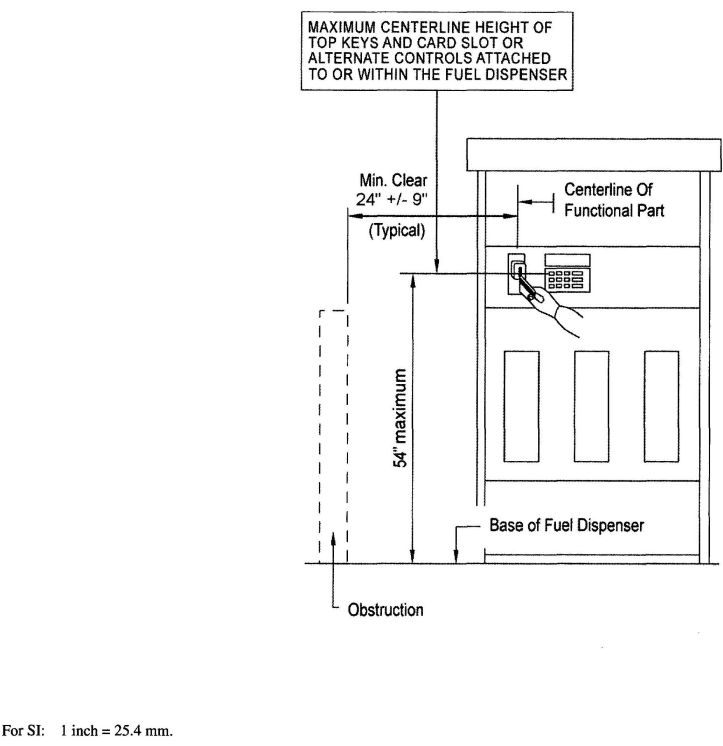
FIGURE 11C-1
CARD READERS MOUNTED IN FUEL DISPENSERS
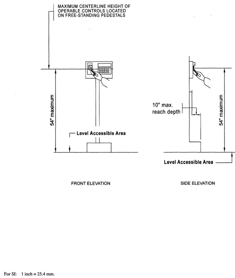
FIGURE 11C-2
CARD READERS LOCATED ON FREE-STANDING PEDESTALS
| Adopting agency | BSC | SFM | HCD | DSA | OSHPD | CSA | DPH | AGR | DWR | CEC | CA | SL | SLC | |||||||
|---|---|---|---|---|---|---|---|---|---|---|---|---|---|---|---|---|---|---|---|---|
| 1 | 2 | 1-AC | AC | SS | SS/CC | 1 | 2 | 3 | 4 | |||||||||||
| Adopt entire chapter | X | X | ||||||||||||||||||
| Adopt entire chapter as amended (amended sections listed below) | X | X | X | X | X | X | X | |||||||||||||
| Adopt only those sections that are listed below | X | |||||||||||||||||||
| Chapter/Section | ||||||||||||||||||||
| 1203.1 | X | X | X | X | ||||||||||||||||
| 1203.3.1.1 | ||||||||||||||||||||
| 1203.3.2 | X | X | ||||||||||||||||||
| 1203.3.2 Item 4 | ||||||||||||||||||||
| 1203.3.2 Exc/ 6 | ||||||||||||||||||||
| 1203.4 | X | X | ||||||||||||||||||
| 1203.4.2.1 | X | X | ||||||||||||||||||
| 1203.5 | X | X | X | |||||||||||||||||
| 1204.1 | X | X | ||||||||||||||||||
| 1204.1 w/Excs/ | X | X | X | X | X | X | ||||||||||||||
| 1205.1 | X | X | ||||||||||||||||||
| 1205.6 | X | |||||||||||||||||||
| 1206 | X | |||||||||||||||||||
| 1207 | X | |||||||||||||||||||
| 1207.1-1207.3;1207.4-1207.13 | X | X | ||||||||||||||||||
| 1208 | X | |||||||||||||||||||
| 1208.1 | X | |||||||||||||||||||
| 1208.2 | X | X | X | X | ||||||||||||||||
| 1208.2.1 | X | X | X | X | ||||||||||||||||
| 1208.4 | X | |||||||||||||||||||
| 1209 | X | |||||||||||||||||||
| 1209.1.1 | ||||||||||||||||||||
| 1210.2 | X | X | ||||||||||||||||||
| 1211 | X | X | ||||||||||||||||||
| 1211 — 1211.6 | X | X | ||||||||||||||||||
| 1224 | X | |||||||||||||||||||
| 1225 | X | |||||||||||||||||||
| 1226 | X | |||||||||||||||||||
| 1227 | X | |||||||||||||||||||
| The Office of the State Fire Marshal's adoption of this chapter or individual sections is applicable to structures regulated by other state agencies pursuant to Section 1.11. | ||||||||||||||||||||
1201.1 Scope. The provisions of this chapter shall govern ventilation, temperature control, lighting, yards and courts, sound transmission, room dimensions, surrounding materials and rodent proofing associated with the interior spaces of buildings.
1202.1 General. The following words and terms shall, for the purposes of this chapter and as used elsewhere in this code, have the meanings shown herein.
SUNROOM. A one-story structure attached to a building with a glazing area in excess of 40 percent of the gross area of the structure's exterior walls and roof.
THERMAL ISOLATION. A separation of conditioned spaces, between a sunroom addition and a dwelling unit, consisting of existing or new wall(s), doors and/or windows.
1203.1 General. Buildings shall be provided with natural ventilation in accordance with Section 1203.4, or mechanical ventilation in accordance with the California Mechanical Code.
Exception: [OSHPD 1,2,3 4] For restrictions on natural ventilation, see California Mechanical Code.
1203.2 Attic spaces. Enclosed attics and enclosed rafter spaces formed where ceilings are applied directly to the underside of roof framing members shall have cross ventilation for each separate space by ventilating openings protected against the entrance of rain and snow. Blocking and bridging shall be arranged so as not to interfere with the movement of air. A minimum of 1 inch (25 mm) of airspace shall be provided between the insulation and the roof sheathing. The net free ventilating area shall not be less than 1/300 of the area of the space ventilated, with 50 percent of the required ventilating area provided by ventilators located in the upper portion of the space to be ventilated at least 3 feet (914 mm) above eave or cornice vents with the balance of the required ventilation provided by eave or cornice vents.
1203.2.1 Openings into attic. Exterior openings into the attic space of any building intended for human occupancy shall be protected to prevent the entry of birds, squirrels, rodents, snakes and other similar creatures. Openings for ventilation having a least dimension of 1/16; inch (1.6 mm) minimum and ¼ inch (6.4 mm) maximum shall be permitted. Openings for ventilation having a least dimension larger than ¼ inch (6.4 mm) shall be provided with corrosion-resistant wire cloth screening, hardware cloth, perforated vinyl or similar material with openings having a least dimension of 1/16 inch (1.6 mm) minimum and ¼ inch (6.4 mm) maximum. Where combustion air is obtained from an attic area, it shall be in accordance with Chapter 7 of the California Mechanical Code.
1203.3 Under-floor ventilation. The space between the bottom of the floor joists and the earth under any building except spaces occupied by basements or cellars shall be provided with ventilation openings through foundation walls or exterior walls. Such openings shall be placed so as to provide cross ventilation of the under-floor space.
1203.3.1 Openings for under-floor ventilation. The minimum net area of ventilation openings shall not be less than 1 square foot for each 150 square feet (0.67 m2 for each 100 m2) of crawl-space area. Ventilation openings shall be covered for their height and width with any of the following materials, provided that the least dimension of the covering shall not exceed ¼ inch (6 mm):
1203.3.1.1 [SPCB] Openings for under-floor ventilation shall be not less than 1 ½ square feet (0.135 m2) for each 25 linear feet (7620 linear mm) of exterior wall. They shall be covered with corrosion-resistant wire mesh with mesh openings not less than ¼ inch (6.4 mm) nor more than ½ inch (13 mm) in any dimension.
1203.3.2 Exceptions. The following are exceptions to Sections 1203.3 and 1203.3.1:
1203.4 Natural ventilation. Natural ventilation of an occupied space shall be through windows, doors, louvers or other openings to the outdoors. The operating mechanism for such openings shall be provided with ready access so that the openings are readily controllable by the building occupants.
[HCD 1] In employee housing, all openable windows in rooms used for living, dining, cooking or sleeping purposes, and toilet and bath buildings, shall be provided and maintained with insect screening.
[HCD 1] Door openings of rooms used for dining, cooking, toilet and bathing facilities in employee housing shall be provided and maintained with insect screening or with solid doors equipped with self-closing devices in lieu thereof, when approved by the enforcement agency.
[HCD 1] The windows, doors, louvers or other approved closeable openings not required by Section 1029 may open into a passive solar energy collector for ventilation required by this section. The area of ventilation openings to the outside of the passive solar energy collector shall be increased to compensate for the openings required by the interior space.
1203.4.1 Ventilation area required. The minimum openable area to the outdoors shall be 4 percent of the floor area being ventilated.
1203.4.1.1 Adjoining spaces. Where rooms and spaces without openings to the outdoors are ventilated through an adjoining room, the opening to the adjoining room shall be unobstructed and shall have an area of not less than 8 percent of the floor area of the interior room or space, but not less than 25 square feet (2.3 m2). The minimum openable area to the outdoors shall be based on the total floor area being ventilated.
Exception: Exterior openings required for ventilation shall be permitted to open into a thermally isolated sunroom addition or patio cover provided that the openable area between the sunroom addition or patio cover and the interior room shall have an area of not less than 8 percent of the floor area of the interior room or space, but not less than 20 square feet (1.86 m2). The minimum openable area to the outdoors shall be based on the total floor area being ventilated.
1203.4.1.2 Openings below grade. Where openings below grade provide required natural ventilation, the outside horizontal clear space measured perpendicular to the opening shall be one and one-half times the depth of the opening. The depth of the opening shall be measured from the average adjoining ground level to the bottom of the opening.
1203.4.2 Contaminants exhausted. Contaminant sources in naturally ventilated spaces shall be removed in accordance with the California Mechanical Code and the California Fire Code.
1203.4.2.1 Bathrooms. Rooms containing bathtubs, showers, spas and similar bathing fixtures shall be mechanically ventilated in accordance with the California Mechanical Code. The minimum ventilation or exhaust rate shall not be less than that established by Table 4-4 “Minimum Exhaust Rates.” See California Mechanical Code for additional provisions related to environmental air ducts.
1203.4.3 Openings on yards or courts. Where natural ventilation is to be provided by openings onto yards or courts, such yards or courts shall comply with Section 1206.
1203.5 Other ventilation and exhaust systems. Ventilation and exhaust systems for occupancies and operations involving flammable or combustible hazards or other contaminant sources as covered in the California Mechanical Code or the California Fire Code shall be provided as required by both codes.
1204.1 Equipment and systems. Interior spaces intended for human occupancy shall be provided with active or passive space-heating systems capable of maintaining a minimum indoor temperature of 68°F (20°C) at a point 3 feet (914 mm) above the floor on the design heating day.
Exceptions:
- Interior spaces where the primary purpose is not associated with human comfort.
- [HCD 1] For limited-density owner-built rural dwellings, a heating facility or appliance shall be installed in each dwelling subject to the provisions of Subchapter 1, Chapter 1, Title 25, California Code of Regulations, commencing with Section 74; however, there shall be no specified requirement for heating capacity or temperature maintenance. The use of solid-fuel or solar-heating devices shall be deemed as complying with the requirements of this section. If nonrenewable fuel is used in these dwellings, rooms so heated shall meet current installation standards.
- [OSHPD 1, 2, 3 & 4] Space heating systems shall comply with the requirements of the California Mechanical Code.
- [HCD 1] When a passive solar energy collector is designed as a conditioned area it shall comply with 594the California Energy Code, Title 24, Part 6. Nonconditioned passive solar energy collectors are exempt from Title 24, Part 6.
1205.1 General. Every space intended for human occupancy shall be provided with natural light by means of exterior glazed openings in accordance with Section 1205.2 or shall be provided with artificial light in accordance with Section 1205.3. Exterior glazed openings shall open directly onto a public way or onto a yard or court in accordance with Section 1206.
[HCD 1] Glazed openings may open into a passive solar energy collector provided the area of exterior glazed openings in the passive solar energy collector is increased to compensate for the area required by the interior space.
1205.2 Natural light. The minimum net glazed area shall not be less than 8 percent of the floor area of the room served.
1205.2.1 Adjoining spaces. For the purpose of natural lighting, any room is permitted to be considered as a portion of an adjoining room where one-half of the area of the common wall is open and unobstructed and provides an opening of not less than one-tenth of the floor area of the interior room or 25 square feet (2.32 m2), whichever is greater.
Exception: Openings required for natural light shall be permitted to open into a thermally isolated sunroom addition or patio cover where the common wall provides a glazed area of not less than one-tenth of the floor area of the interior room or 20 square feet (1.86 m2), whichever is greater.
1205.2.2 Exterior openings. Exterior openings required by Section 1205.2 for natural light shall open directly onto a public way, yard or court, as set forth in Section 1206.
Exceptions:
- Required exterior openings are permitted to open into a roofed porch where the porch:
- Abuts a public way, yard or court;
- Has a ceiling height of not less than 7 feet (2134 mm); and
- Has a longer side at least 65 percent open and unobstructed.
- Skylights are not required to open directly onto a public way, yard or court.
1205.3 Artificial light. Artificial light shall be provided that is adequate to provide an average illumination of 10 foot-candles (107 lux) over the area of the room at a height of 30 inches (762 mm) above the floor level.
1205.4 Stairway illumination. Stairways within dwelling units and exterior stairways serving a dwelling unit shall have an illumination level on tread runs of not less than 1 foot-candle (11 lux). Stairs in other occupancies shall be governed by Chapter 10.
1205.4.1 Controls. The control for activation of the required stairway lighting shall be in accordance with the California Electrical Code.
1205.5 Emergency egress lighting. The means of egress shall be illuminated in accordance with Section 1006.1.
1205.6 Campus lighting for parking facilities and primary walkways at california state universities, colleges, and community colleges. Artificial light shall be provided for parking facilities and primary walkways at California State Universities, colleges, and community colleges in accordance with provisions of this subsection. This subsection shall not apply to the University of California unless the Regents of the University of California, by resolution, make it applicable.
1205.6.1 Lighting requirements. Based on the recommendations of the most current edition of the Illumination Engineering Society lighting handbook, the following lighting standards shall be used for all new construction of open parking facilities, covered parking facilities and primary walkways:
1206.1 General. This section shall apply to yards and courts adjacent to exterior openings that provide natural light or ventilation. Such yards and courts shall be on the same property as the building.
1206.2 Yards. Yards shall not be less than 3 feet (914 mm) in width for buildings two stories or less above grade plane. For buildings more than two stories above grade plane, the minimum width of the yard shall be increased at the rate of 1 foot (305 mm) for each additional story. For buildings exceeding 14 stories above grade plane, the required width of the yard shall be computed on the basis of 14 stories above grade plane.
1206.3 Courts. Courts shall not be less than 3 feet (914 mm) in width. Courts having windows opening on opposite sides shall not be less than 6 feet (1829 mm) in width. Courts shall not be less than 10 feet (3048 mm) in length unless bounded on one end by a public way or yard. For buildings more than two stories above grade plane, the court shall be increased 1 foot (305 mm) in width and 2 feet (610 mm) in length for each additional story. For buildings exceeding 14 stories above grade plane, the required dimensions shall be computed on the basis of 14 stories above grade plane.
1206.3.1 Court access. Access shall be provided to the bottom of courts for cleaning purposes.
1206.3.2 Air intake. Courts more than two stories in height shall be provided with a horizontal air intake at the bottom not less than 10 square feet (0.93 m2) in area and leading to the exterior of the building unless abutting a yard or public way
1206.3.3 Court drainage. The bottom of every court shall be properly graded and drained to a public sewer or other approved disposal system complying with the California Plumbing Code.
1207.1 Purpose and scope. The purpose of this section is to establish uniform minimum noise insulation performance standards to protect persons within hotels, motels, dormitories, apartment houses and dwellings other than detached single-family dwellings from the effects of excessive noise, including, but not limited to, hearing loss or impairment and interference with speech and sleep. This section shall apply to all buildings for which applications for building permits were made subsequent to August 22, 1974.
1207.2 Definitions. The following special definitions shall apply to this section:
SOUND TRANSMISSION CLASS (STC) is a single-number rating used to compare walls, floor-ceiling assemblies and doors for their sound-insulating properties with respect to speech and small household appliance noise. The STC is derived from laboratory measurements of sound transmission loss across a series of 16 test bands.
Laboratory STC ratings should be used to the greatest extent possible in determining that the design complies with this section.
FIELD SOUND TRANSMISSION CLASS (FSTC) is a single-number rating similar to STC, except that the transmission loss values used to derive the FSTC are measured in the field. All sound transmitted from the source room to the receiving room is assumed to be through the separating wall or floor-ceiling assembly.
This section does not require determination of the FSTC, and field-measured values of noise reduction should not be reported as transmission loss.
IMPACT INSULATION CLASS (IIC) is a single-number rating used to compare the effectiveness of floor-ceiling assemblies in providing reduction of impact-generated sounds such as footsteps. The IIC is derived from laboratory measurements of impact sound pressure level across a series of 16 test bands using a standardized tapping machine. Laboratory IIC ratings should be used to the greatest extent possible in determining that the design complies with this section.
FIELD IMPACT INSULATION CLASS (FIIC) is a single-number rating similar to the IIC, except that the impact sound pressure levels are measured in the field
NOISE ISOLATION CLASS (NIC) is a single-number rating derived from measured values of noise reduction between two enclosed spaces that are connected by one or more paths. The NIC is not adjusted or normalized to a standard reverberation time.
NORMALIZED NOISE ISOLATION CLASS (NNIC) is a single-number rating similar to the NIC, except that the measured noise reduction values are normalized to a reverberation time of one-half second.
NORMALIZED A-WEIGHTED SOUND LEVEL DIFFERENCE (Dn) means for a specified source room sound spectrum, Dn is the difference, in decibels, between the average sound levels produced in two rooms after adjustment to the expected acoustical conditions when the receiving room under test is normally furnished.
DAY-NIGHT AVERAGE SOUND LEVEL (Ldn) is the A-weighted equivalent continuous sound exposure level for a 24-hour period with a 10 db adjustment added to sound levels occurring during nighttime hours (10 p.m. to 7 a.m.).
COMMUNITY NOISE EQUIVALENT LEVEL (CNEL) is a metric similar to the Ldn, except that a 5 db adjustment is added to the equivalent continuous sound exposure level for evening hours (7 p.m. to 10 p.m.) in addition to the 10 db nighttime adjustment used in the Ldn.
1207.3 Relevant standards. The current edition of the following standards is generally applicable for determining compliance with this section. Copies may be obtained from the American Society for Testing and Materials (ASTM) at 100 Barr Harbor Drive, West Conshohoken, PA, 19428-2959.
596ASTM C 634, Standard Terminology Relating to Building and Environmental Acoustics.
ASTM E 90, Standard Test Method for Laboratory Measurement of Airborne Sound Transmission Loss of Building Partitions and Elements.
ASTM E 336, Standard Test Method for Measurement of Airborne Sound Attenuation Between Rooms in Buildings.
ASTM E 413, Classification for Rating Sound Insulation.
ASTM E 492, Standard Test Method for Laboratory Measurement of Impact Sound Transmission Through Floor-Ceiling Assemblies Using the Tapping Machine.
ASTM E 497, Standard Recommended Practice for Installation of Fixed Partitions of Light Frame Type for the Purpose of Conserving Their Sound Insulation Efficiency.
ASTM E 597, Recommended Practice for Determining a Single-Number Rating of Airborne Sound Isolation in Multi-unit Building Specifications.
ASTM E 966, Standard Guide for Field Measurements of Airborne Sound Insulation of Building Facades and Facade Elements.
ASTM E 989, Standard Classification for Determination of Impact Insulation Class (IIC).
ASTM E 1007, Standard Test Method for Field Measurement of Tapping Machine Impact Sound Transmission Through Floor-Ceiling Assemblies and Associated Support Structures.
ASTM E 1014, Standard Guide for Measurement of Outdoor A-Weighted Sound Levels.
1207.4 Complaints. Where a complaint as to noncompliance with this chapter requires a field test, the complainant shall post a bond or adequate funds in escrow for the cost of said testing. Such costs shall be chargeable to the complainant if the field tests show compliance with this chapter. If the tests show noncompliance, testing costs shall be borne to the owner or builder.
1207.5 Local modification. The governing body of any city or county or city and county may, by ordinance, adopt changes or modifications to the requirements of this section as set forth in Section 17922.7 of the Health and Safety Code.
1207.6 Interdwelling sound transmission control.
1207.6.1 Wall and floor-ceiling assemblies. Wall and floor-ceiling assemblies separating dwelling units or guest rooms from each other and from public or service areas such as interior corridors, garages and mechanical spaces shall provide airborne sound insulation for walls, and both airborne and impact sound insulation for floor-ceiling assemblies.
Exception: Impact sound insulation is not required for floor-ceiling assemblies over nonhabitable rooms or spaces not designed to be occupied, such as garages, mechanical rooms or storage areas.
1207.7 Airborne sound insulation. All such acoustically rated separating wall and floor-ceiling assemblies shall provide airborne sound insulation equal to that required to meet a sound transmission class (STC) rating of 50 based on laboratory tests as defined in ASTM E 90 and E 413. Field-tested assemblies shall meet a noise isolation class (NIC) rating of 45 for occupied units and a normalized noise isolation class (NINIC) rating of 45 for unoccupied units as defined in ASTM E 336 and E 413.
ASTM E 597 may be used as simplified procedure for field tests of the airborne sound isolation between rooms in unoccupied buildings. In such tests, the minimum value of Dn is 45 db for compliance.
Entrance doors from interior corridors together with their perimeter seals shall have STC ratings not less than 26. Such tested doors shall operate normally with commercially available seals.
Solid-core wood-slab doors 1 3/8 inches (35 mm) thick minimum or 18 gauge insulated steel-slab doors with compression seals all around, including the threshold, may be considered adequate without other substantiating information.
Field tests of corridor walls should not include segments with doors. If such tests are impractical, however, the NIC or NNIC rating for the composite wall-door assembly shall not be less than 30.
Penetrations or openings in construction assemblies for piping, electrical devices, recessed cabinets, bathtubs, soffits or heating, ventilating or exhaust ducts shall be sealed, lined, insulated or otherwise treated to maintain the required ratings.
1207.8 Impact sound insulation. All acoustically rated separating floor-ceiling assemblies shall provide impact sound insulation equal to that required to meet a IIC rating of 50 based on laboratory tests as defined in ASTM E 492 and E 989. Field-tested assemblies shall meet a field impact insulation class (FIIC) rating of 45 for both occupied and unoccupied units as defined in ASTM E 1007 and E 989, with the exception that the measured impact sound pressure levels shall not be normalized to a standard amount of absorption in the receiving room.
Floor coverings may be included in the assembly to obtain the required ratings. These coverings must be retained as a permanent part of the assembly and may be replaced only by other floor coverings that provide the required impact sound insulation.
1207.9 Tested assemblies. Laboratory-tested wall or floor-ceiling designs having STC or IIC ratings of 50 or more may be used by the building official to determine compliance with this section during plan review phase. Field tests shall be required by the building official when evidence of sound leaks or flanking paths is noted, or when the separating assembly is not built according to the approved design.
Generic sound transmission control systems as listed in the Catalog of STC and IIC Ratings for Wall and Floor-Ceiling Assemblies, as published by the Office of Noise Control, California Department of Health Services, or the Fire Resistance Design Manual, as published by the Gypsum Association, may be used to evaluate construction assemblies for their sound transmission properties. Other tests from recognized laboratories may also be used. When ratings for essentially similar assemblies differ, and when ratings are below STC or IIC 50, field testing may be used to demonstrate that the building complies with this section.
For field testing, rooms should ideally be large and reverberant for reliable measurements to be made in all test bands. This is often not possible for bathrooms, kitchens, hallways or rooms with large amounts of sound-absorptive materials. Field test results should, however, report the measured values in all bands, noting those which do not meet relevant ASTM criteria for diffusion.
It should be noted that STC ratings do not adequately characterize the sound insulation of construction assemblies when the intruding noise is predominantly low-pitched, as is often produced by amplified music or by large pieces of mechanical equipment.
It should also be noted that the transmission of impact sound from a standardized tapping machine may vary considerably for a given design due to differences in specimen size, flanking transmission through associated structure and the acoustical response of the room below. Laboratory IIC values should therefore be used with caution when estimating the performance of hard-surfaced floors in the field. Additionally, IIC ratings may not always be adequate to characterize the subjectively annoying creak or boom generated by footfalls on a lumber floor.
1207.10 Certification. Field testing, when required, shall be done under the supervision of a person experienced in the field of acoustical testing and engineering, who shall forward test results to the building official showing that the sound isolation requirements stated above have been met. Documentation of
597field test results should generally follow the requirements outlined in relevant ASTM standards.
1207.11 Exterior sound transmission control.
1207.11.1 Application. Consistent with local land-use standards, residential structures located in noise critical areas, such as proximity to highways, county roads, city streets, railroads, rapid transit lines, airports or industrial areas, shall be designed to prevent the intrusion of exterior noises beyond prescribed levels. Proper design shall include, but shall not be limited to, orientation of the residential structure, setbacks, shielding and sound insulation of the building itself.
1207.11.2 Allowable interior noise levels. Interior noise levels attributable to exterior sources shall not exceed 45 db in any habitable room. The noise metric shall be either the day-night average sound level (Ldn) or the community noise equivalent level (CNEL), consistent with the noise element of the local general plan.
Note: Ldn is the preferred metric for implementing these standards. Worst-case noise levels, either existing or future, shall be used as the basis for determining compliance with this section. Future noise levels shall be predicted for a period of at least 10 years from the time of building permit application.
1207.11.3 Airport noise sources. Residential structures to be located where the annual Ldn or CNEL (as defined in Title 21, Division 2.5, Chapter 6, Article 1, Section 5001, California Code of Regulations) exceeds 60 db shall require an acoustical analysis showing that the proposed design will achieve prescribed allowable interior level. For public-use airports or heliports, the Ldn or CNEL shall be determined from the airport land-use plan prepared by the county wherein the airport is located. For military bases, the Ldn shall be determined from the facility Air Installation Compatible Use Zone (AICUZ) plan. For all other airports or heliports, or public-use airports or heliports for which a land-use plan has not been developed, the Ldn or CNEL shall be determined from the noise element of the general plan of the local jurisdiction.
When aircraft noise is not the only significant source, noise levels from all sources shall be added to determine the composite site noise level.
1207.11.4 Other noise sources. Residential structures to be located where the Ldn or CNEL exceeds 60 db shall require an acoustical analysis showing that the proposed design will limit exterior noise to the prescribed allowable interior level. The noise element of the local general plan shall be used to the greatest extent possible to identify sites with noise levels potentially greater than 60 db.
1207.12 Compliance. Evidence of compliance shall consist of submittal of an acoustical analysis report, prepared under the supervision of a person experienced in the field of acoustical engineering, with the application for a building permit. The report shall show topographical relationships of noise sources and dwelling sites, identification of noise sources and their characteristics, predicted noise spectra and levels at the exterior of the proposed dwelling structure considering present and future land usage, basis for the prediction (measured or obtained from published data), noise attenuation measures to be applied, and an analysis of the noise insulation effectiveness of the proposed construction showing that the prescribed interior noise level requirements are met.
If interior allowable noise levels are met by requiring that windows be unopenable or closed, the design for the structure must also specify a ventilation or air-conditioning system to provide a habitable interior environment. The ventilation system must not compromise the dwelling unit or guest room noise reduction.
1207.13 Field testing. When inspection indicates that the construction is not in accordance with the approved design, or that the noise reduction is compromised due to sound leaks or flanking paths, field testing may be required. A test report showing compliance or noncompliance with prescribed interior allowable levels shall be submitted to the building official.
Measurements of outdoor sound levels shall generally follow the guidelines in ASTM E 1014.
Field measurements of the A-weighted airborne sound insulation of buildings from exterior sources shall generally follow the guidelines in ASTM E 966.
For the purpose of this standard, sound level differences measured in unoccupied units shall be normalized to a receiving room reverberation time of one-half second. Sound level differences measured in occupied units shall not be normalized to a standard reverberation time.
1208.1 Minimum room widths. Habitable spaces, other than a kitchen, shall not be less than 7 feet (2134 mm) in any plan dimension. Kitchens shall have a clear passageway of not less than 3 feet (914 mm) between counter fronts and appliances or counter fronts and walls.
[HCD 1] For limited-density owner-built rural dwellings, there shall be no requirements for room dimensions, provided there is adequate light and ventilation and adequate means of egress.
1208.2 Minimum ceiling heights. Occupiable spaces, habitable spaces and corridors shall have a ceiling height of not less than 7 feet 6 inches (2286 mm). Bathrooms, toilet rooms, kitchens, storage rooms and laundry rooms shall be permitted to have a ceiling height of not less than 7 feet (2134 mm).
Exceptions:
- In one- and two-family dwellings, beams or girders spaced not less than 4 feet (1219 mm) on center and projecting not more than 6 inches (152 mm) below the required ceiling height.
- If any room in a building has a sloped ceiling, the prescribed ceiling height for the room is required in one-half the area thereof. Any portion of the room measuring less than 5 feet (1524 mm) from the finished floor to the ceiling shall not be included in any computation of the minimum area thereof.598
- Mezzanines constructed in accordance with Section 505.1.
- [OSHPD 1 & 2] Minimum ceiling heights shall comply with Section 1224.4.10.
- [OSHPD 3] Minimum ceiling heights shall comply with Section 1226.8.
- [OSHPD 4] Minimum ceiling heights shall comply with Section 1227.8.
1208.2.1 Furred ceiling. Any room with a furred ceiling shall be required to have the minimum ceiling height in two-thirds of the area thereof, but in no case shall the height of the furred ceiling be less than 7 feet (2134 mm).
Exception: [OSHPD 1, 2, 3 & 4] Minimum ceiling heights shall comply with Section 1208.2
1208.3 Room area. Every dwelling unit shall have at least one room that shall have not less than 120 square feet (13.9 m2) of netfloor area. Other habitable rooms shall have a net floor area of not less than 70 square feet (6.5 m2).
Exception: Every kitchen in a one-and two-family dwelling shall have not less than 50 square feet (4.64 m2) of gross floor area.
1208.4 Efficiency dwelling units. [HCD 1] Unless modified by local ordinance pursuant to Health and Safety Code Section 17958.1, efficiency dwelling units shall comply with the following:
[HCD 1] For additional information, see Health and Safety Code Section 17958.1.
1209.1 Crawl spaces. Crawl spaces shall be provided with a minimum of one access opening not less than 18 inches by 24 inches (457 mm by 610 mm).
1209.1.1 [SPCB] Accessible under-floor areas shall be provided with an 18-inch by 24-inch (457 mm by 610 mm) access crawl hole. Pipes, ducts and other nonstructural construction shall not interfere with the accessibility to or within under-floor areas.
1209.2 Attic spaces. An opening not less than 20 inches by 30 inches (559 mm by 762 mm) shall be provided to any attic area having a clear height of over 30 inches (762 mm). A 30-inch (762 mm) minimum clear headroom in the attic space shall be provided at or above the access opening.
1209.3 Mechanical appliances. Access to mechanical appliances installed in under-floor areas, in attic spaces and on roofs or elevated structures shall be in accordance with the California Mechanical Code.
1210.1 Floors and wall base finish materials. In other than dwelling units, toilet, bathing and shower room floor finish materials shall have a smooth, hard, nonabsorbent surface. The intersections of such floors with walls shall have a smooth, hard, nonabsorbent vertical base that extends upward onto the walls at least 4 inches (102 mm).
1210.2 Walls and partitions. Walls and partitions within 2 feet (610 mm) of urinals and water closets shall have a smooth, hard, nonabsorbent surface, to a height of 4 feet (1219 mm) above the floor, and except for structural elements, the materials used in such walls shall be of a type that is not adversely affected by moisture.
Exceptions:
- Dwelling units and sleeping units.
- Toilet rooms that are not accessible to the public and which have not more than one water closet.
Accessories such as grab bars, towel bars, paper dispensers and soap dishes, provided on or within walls, shall be installed and sealed to protect structural elements from moisture.
1210.3 Showers. Shower compartments and walls above bathtubs with installed shower heads shall be finished with a smooth, nonabsorbent surface to a height not less than 70 inches (1778 mm) above the drain inlet.
1210.4 Waterproof joints. Built-in tubs with showers shall have waterproof joints between the tub and adjacent wall.
1210.5 Toilet rooms. Toilet rooms shall not open directly into a room used for the preparation of food for service to the public.
1211.1 General. This section shall apply to applications listed in Sections 1.8.2.1.1 and 1.8.2.1.3 regulated by the Department of Housing and Community Development.
1211.1.1 Extension garage door springs. Every extension garage door spring sold or offered for sale, whether new or as a replacement, or installed in any garage or carport which is accessory to an apartment house, hotel, motel or dwelling shall conform to the following requirements:
Hard-drawn spring wire shall conform to ASTM A 227-71 or a more current version, and shall be made by the steel processes described therein, conforming to the chemical composition requirements listed and meeting the standards of steel heat as set forth by the ladle analysis. Wire tensile strength and dimension variations shall meet the prescribed properties of established standards.
599Oil-tempered wire shall conform to ASTM A 229-71 or a more current version, and shall be made by the steel processes described therein conforming to the chemical composition requirements listed and meeting the standards of steel heat as set forth by the ladle analysis. Wire tensile strength and dimension variations shall meet the prescribed properties of established standards.
Extension springs shall be fabricated from either hard drawn spring wire or oil-tempered wire as specified above.
1211.2 Design standards. Minimum design standard shall be 9,000 cycles. (One cycle is equal to door opening plus door closing at maximum working load.)
1211.3 Certification.
Mill certification of wire physical tests and chemical properties shall be kept on file by the spring manufacturer.
Physical cycling tests shall be performed for each extension spring design and shall be certified by an approved testing agency acceptable to the department and reports kept on file by the manufacturer.
Containment devices shall be physically tested for each extension spring design by installing the device on the spring and by destroying the spring at maximum recommended stretch. Containment tests shall be certified by an approved testing agency acceptable to the department and reports kept on file by the manufacturer.
1211.4 Containment devices. Each extension spring shall be equipped with an approved device capable of restraining the spring or any part thereof in the event it breaks.
1211.5 Identification. Extension springs shall be permanently identified as to manufacturer and also to indicate maximum recommended stretch. Both extension springs and containment devices shall bear information stating that they have been manufactured in accordance with requirements of the California Department of Housing and Community Development.
1211.6 Installation. Installation of extension springs, containment devices and hardware shall be in accordance with the manufacturer's installation instructions. Instructions shall be provided by the manufacturer and shall specify the approved method of restraint and maximum recommended stretch. Unless otherwise permitted by the manufacturer's installation instructions, the hardware and extension springs shall be mounted to nominal 12 by 6 framing members which shall be a species identified as Group I or II in Volume 3, Chapter 23, Division III.
Reserved
Reserved
Reserved
Reserved
Reserved
Reserved
Reserved
Reserved
Reserved
Reserved
Reserved
Reserved
1224.1 Scope. The provisions of this section shall apply to general acute-care hospitals, acute psychiatric hospitals and general acute-care hospitals providing only acute medical rehabilitation center services. The provisions of Section 1225 shall apply to distinct part skilled nursing and intermediate-care services on a general acute-care or acute psychiatric hospital license, provided either in a separate unit or a freestanding building.
1224.2 Application. New buildings and additions, alterations or repairs to existing buildings subject to licensure shall comply with applicable provisions of the California Electrical Code, California Mechanical Code, California Plumbing Code, California Fire Code (Parts 3, 4, 5 and 9 of Title 24) and this section.
Exceptions:
- Facilities licensed and in operation prior to the effective date of this section shall not be required to institute corrective alterations or construction to comply with any new requirements imposed thereby or subsequently, except where specifically required or where the enforcing agency determines that a definite hazard 600to health and safety exists. Facilities for which preliminary drawings have been submitted to the enforcing agency prior to the effective date of this change shall not be required to comply with such new requirements, provided working drawings are submitted within one year of the effective date of such new requirements.
- The provisions of this section do no prohibit the use of alternate space utilization, new concepts of design, treatment techniques, equipment and alternate finish materials provided the intent of this section is accommodated and written approval for such alternative is granted by the enforcing agency. Written substantiating evidence in support of the alternate and a written request for consideration shall be submitted to the enforcing agency.
- Nothing in this section shall prohibit the provisions of required services from a centralized service facility serving two or more licensed facilities when approved in writing by the licensing agency. Buildings and required spaces for services facility shall comply with all applicable provisions of these regulations and applicable local codes and ordinances for the services so provided.
- Acute psychiatric hospitals and general acute-care hospitals providing only acute medical rehabilitation center services may provide for surgical and anesthesia services to be provided by an outside licensed facility when approved by the licensing agency.
- When the Corrections Standards Authority, the Department of Corrections or the Department of Youth Authority determines that a particular requirement for hospitals located in a correctional facility may compromise the safety, security or protection of staff, inmates or property, the enforcement agency shall consider an alternate design.
1224.3 Definitions. For the purpose of this section, the following terms shall have the meaning indicated:
AIR CONDITIONING. The process or system by which simultaneously the temperature, humidity, air motion and quality are maintained within required limits.
AIRBORNE INFECTION ISOLATION ROOM. A single-occupancy patient room where environmental factors are controlled in an effort to minimize the transmission of those infectious agents usually spread from person to person by droplet nuclei associated with coughing and inhalation.
AMBULATORY CARE. A defined health care encounter(s) of less than 24 hours in duration that requires direct professional health care support within a specific facility.
AMBULATORY SURGICAL FACILITY. Any surgical facility organized for the purpose of providing procedural, invasive surgical care to patients with the expectation that they will be recovered sufficiently to be discharged in less than a 24-hour period.
BASIC SERVICES. Those essential services required for licensure as a hospital, including medical, nursing, surgical, anesthesia, laboratory, radiology, pharmacy, dietary services and support services. See ″ SUPPLEMENTAL SERVICES″.
BIOTERRORISM. The use, or threat of use, of biological agents to intimidate a political entity or population group.
CENTRAL AIR-HANDLING SYSTEMS. Any units requiring ductwork on the supply or inlet side and serving more than one room.
COURT. An open exterior space bounded on three or more sides by the walls of a structure.
ENVIRONMENT OF CARE. Those features in a built health care entity that are created, structured, and maintained to support quality health care.
FLOOR AREA, CLEAR. The actual occupied area exclusive of fixed or wall-mounted cabinets, built-in shelves, toilet rooms, closets, lockers, wardrobes, alcoves, anterooms or vestibules.
GENERAL ACUTE-CARE HOSPITAL. A hospital, licensed by the Department of Health Services, having a duly constituted governing body with overall administrative and professional responsibility and an organized medical staff which provides 24-hour inpatient care, including the basic services.
GOOSENECK SPOUT. A deck or fixture-mounted spout shaped so the discharge point is at least 5 inches (127 mm) above the fixture rim.
HANDWASHING FIXTURE. A special application sink having a water supply spout mounted so the discharge point is at least 5 inches (127 mm) above the fixture rim and equipped with hot and cold supply controls not requiring direct contact of the hands for operation. The fixture cannot be equipped with a nonaerating laminar flow blade handles, but may be equipped with an aerator and wrist or elbow blade handles, but may be equipped with a nonaerating laminar flow device. Sensor operated fixtures may be used, provided they are either battery operated or connected to the essential electrical system.
HOSPITAL. A general acute-care hospital, including those providing only acute medical rehabilitation center services and acute psychiatric hospitals.
HOUSEKEEPING. Services anywhere within a health care facility that include general cleaning and tidying and the provision and positioning of identified materials, e.g., soaps, towels, etc. (While routine disinfection protocols can be included in such a definition, the definition is not intended to include complex, nonroutine disinfection procedures nor the nonroutine disposition of hazardous materials such as potentially toxic drugs or other chemicals and radioactive wastes.)
LDR. Labor, Delivery, Recovery (an unlicensed patient bed)
LDRP. Labor, Delivery, Recovery, Postpartum (a licensed patient bed)
LICENSING AGENCY. The Department of Public Health, Licensing and Certification.
NURSING UNIT. A designated patient care area of the hospital which is planned, organized, operated and maintained to function as a unit. It includes patient rooms with adequate support facilities, services and personnel providing nursing care and necessary management of patients.
601OPERATING ROOM. A room specifically designed for the performance of surgical procedures. (In common understanding, this means most types of surgical procedures, especially those involving the administration of anesthesia, multiple personnel, recovery room access, and a fully controlled environment.)
OUTPATIENT SERVICE. An organizational unit of the hospital, which provides nonemergency healthcare services to patients.
PATIENT ROOM. Licensed patient bed rooms.
PERIOPERATIVE. Patient care and other related supportive activities before, during or after the operative event.
PROTECTIVE ENVIRONMENT. A bedded unit or patient room where severely immunosuppressed patients are cared for.
SCRUB SINK. A sink used to wash and scrub the hands and arms during the aseptic preparation for surgery, and equipped with a supply spout and controls as required for a handwashing fixture.
SERVICE SINK. A sink located in a housekeeping room and designed for the purpose of cleaning mops and the disposal of waste water.
SUB-ACUTE CARE. A segment within a continuum of levels of care determined by patient acuity, clinical stability, and resource needs.
SUPPLEMENTAL SERVICE. An inpatient or outpatient service which is not required to be provided by law or regulation for licensure. A supplemental service, when provided, must accommodate the provisions of this section.
Note: See ″BASIC SERVICES.″
SURGICAL SERVICE SPACE. A space that includes the operating room(s) and service areas.
1224.4 GENERAL CONSTRUCTION.
1224.4.1 Services/systems and utilities. Services/systems and utilities that are necessary to the operation of an acute care hospital, skilled nursing facility, intermediate care facility, or correctional treatment center shall meet the structural requirements of this section. Examples of services/systems and utilities include normal power; emergency power; nurse call; fire alarm; communication and data systems; space-heating systems; process load systems; cooling systems; domestic hot and cold water systems; fire-suppression systems; building drain and sewer systems;. and medical gas systems that support basic and supplemental services.
Services from and acute care hospital, skilled nursing facility or a correctional treatment center may serve a building that does not comply with the structural requirements of the 1973 edition or later edition of the California Building Standards Code with prior approval of the Office.
Exception: Remodel projects that use available existing services/systems and utilities are exempted from the requirements of this section. The enforcing agency may exempt minor addition, minor alteration, and minor remodel projects and projects to upgrade existing services/systems and utilities from the requirements of this section.
1224.4.1.1 Services/systems and utilities for hospital buildings.
1224.4.1.1.1 Additions, alterations, and remodels of conforming (SPC-3, -4 or -5) hospital buildings. Services/systems and utilities for new buildings and additions, and alterations or remodels to existing conforming buildings shall originate in hospital buildings that have OSHPD- approved performance categories of SPC-3 or higher and NPC-4 or higher The services/system and utilities shall not pass through or under buildings that do not have OSHPD-approved performance categories of SPC-2 or higher and NPC-4 or higher.
Exceptions:
- Remodel and alteration projects that use available existing services/systems and utilities are exempted from these requirements.
- Services/systems and utilities may pass through or under building that have OSHPD-approved nonstructural performance categories of NPC-2 or NPC-3, provided that the service/systems and utilities feeding the new building addition, alteration, or remodel conform with ASCE 7, Chapter 13 as modified in Section 1615A and are deemed by OSHPD to be free of adverse seismic interactions caused by potential failure of overhead or adjacent components.
1224.4.1.1.2 Additions, alterations and remodels of SPC-2 hospitals buildings. Service/systems and utilities for additions, alterations or remodel of SPC-2 hospital buildings may originate in and pass through or under SPC-2 or better buildings that have an OSHPD-approved nonstructural performance category of NPC-3 or higher.
Exception: Services/systems and utilities may pass through or under buildings that have OSHPD-approved nonstructural performance categories of NPC-2, provided that the services/systems and utilities feeding the addition, alteration, or remodel conform with ASCE 7, Chapter 13 as modified by Section 1615A and are deemed by OSHPD to be free of adverse seismic interactions caused by potential failure of overhead or adjacent components.
1224.4.1.1.3 Alterations and remodels of SPC-1 hospital buildings. Services/systems and utilities for alterations or remodels of SPC-1 hospital buildings may originate in and pass through or under SPC-1 or better buildings that have and OSHPD-approved nonstructural performance category of NPC-2 or higher.
602| LOCATION | OXYGEN | VACUUM | MEDICAL AIR | |
|---|---|---|---|---|
| 1 | Patient rooms (medical and surgical) | 1/bed | 1/bed | - |
| 2 | Examination or treatment (medical, surgical, and postpartum care) | 1/room | 1/room | - |
| 3 | Airborne infection isolation or protective environment rooms (medical and surgical) | 1/bed | 1/bed | - |
| 4 | Seclusion room (medical, surgical, and postpartum) | 1/bed | 1/bed | - |
| 5 | Intensive care (general) | 3/bed | 3/bed | 1/bed |
| 6 | Airborne infection isolation | 3/bed | 3/bed | 1/bed |
| 7 | Coronary-care service space | 3/bed | 2/bed | 1/bed |
| 8 | Pediatric intensive care | 3/bed | 3/bed | 1/bed |
| 9 | Newborn intensive care | 3/bassinet | 3/bassinet | 3/bassinet |
| 10 | Newborn nursery (full term) | ¼bassinets2 | ¼bassinets2 | ¼bassinets2 |
| 11 | Pediatric and adolescent | 1/bed | 1/bed | 1/bed |
| 12 | Pediatric nursery | 1/bassinet | 1/bassinet | 1/bassinet |
| 13 | Psychiatric patient room | - | - | - |
| 14 | Seclusion treatment room | - | - | - |
| 15 | General operating room | 2/room | 3/room | - |
| 16 | Cardio, ortho, neurological | 2/room | 3/room | - |
| 17 | Orthopedic surgery | 2/room | 3/room | - |
| 18 | Surgical cysto and endo | 1/room | 3/room | - |
| 19 | Post-anesthesia care unit | 1/bed | 3/bed | 1/bed |
| 20 | Anesthesia workroom | 1 per workstation | - | 1 per workstation |
| 21 | Not used | - | - | - |
| 22 | Postpartum bedroom | 1/bed | 1/bed | - |
| 23 | Cesarean operating/delivery room | 2/room | 3/room | 1/room |
| 24 | Infant resuscitation space4 | 1/bassinet | 1/bassinet | 1/bassinet |
| 25 | Labor room | 1/room | 1/room | 1/room |
| 26 | OB recovery room | 1/bed | 3/bed | 1/room |
| 27 | Labor/delivery/recovery (LDR)5 | 1/bed | 1/bed | - |
| 28 | Labor/deliver/recovery/postpartum (LDRP)5 | 1/bed | 1/bed | - |
| 29 | Initial emergency management | 1/bed | 1/bed | - |
| 30 | Triage area (definitive emergency care) | 1/station | 1/station | - |
| 31 | Definitive emergency care examination or treatment rooms | 1/bed | 1/bed | 1/bed |
| 32 | Definitive emergency care observation unit | 1/bed | 1/bed | - |
| 33 | Trauma/cardiac room(s) | 2/bed | 3/bed | 1/bed |
| 34 | Orthopedic and cast room | 1/room | 1/room | - |
| 35 | Cardiac catheterization lab | 2/bed | 2/bed | 2/bed |
| 36 | Autopsy room | - | 1 per workstation | - |
| 37 | MRI | 1/room | 1/room | 1/room |
| 1.For any area or room not described above, the facility clinical staff shall determine outlet requirements after consultation with the enforcing agency. | ||||
| 2. Four bassinets may share one outlet that is accessible to each bassinet. | ||||
| 3. Not used. | ||||
| 4. When infant resuscitation takes place in a room such as cesarean section/delivery or LDRP, then the infant resuscitation services must be provided in that room in addition to the minimum service required for the mother. | ||||
| 5. Two outlets for mother and two for one bassinet. | ||||
| 6. Renovation projects of existing spaces where the existing function is not changed, are not required to comply with the requirements of Table 1224.2. | ||||
| NEW CONSTRUCTION | AIRBORNE SOUND TRANSMISSION CLASS (STC)1 | |
|---|---|---|
| Partitions | Floors | |
| Patient room to patient room | 45 | 40 |
| Public space to patient room3 | 55 | 40 |
| Service areas to patient room4 | 65 | 45 |
| Patient room access corridor5 | 45 | 45 |
| Exam room to exam room | 45 | - |
| Exam room to public space | 45 | - |
| Toilet room to public space | 45 | - |
| Consultation rooms/conference rooms to public space | 45 | - |
| Consultation rooms/conference rooms to patient rooms | 45 | - |
| Staff lounges to patient rooms | 45 | - |
| 1. Sound Transmission Class (STC) shall be determined by tests in accordance with methods set forth in ASTM 90 and ASTM 413. Where partitions do not extend to the structure above, sound transmission through ceilings and composite STC performance shall be considered. | ||
| 2. Treatment rooms shall be treated the same as patient rooms. | ||
| 3. Public space includes corridors (except patient room access corridors), lobbies, dining rooms, recreation rooms and similar space. | ||
| 4. Service areas for the purposes of this table include kitchens, elevators, elevator machine rooms, laundries, garages, maintenance rooms, boiler and mechanical equipment rooms, and similar spaces of high noise. Mechanical equipment located on the same floor or above patient rooms, offices, nurses stations and similar occupied space shall be effectively isolated from the floor. | ||
| 5. Patient room access corridors contain composite walls with doors/windows and have direct access to patient rooms. | ||
| 6. Renovation projects of existing spaces where the existing function is not changed, are not required to comply with the requirements of Table 1224.3. | ||
1224.4.1.1.4 Buildings without SPC/NPC ratings. When services/systems and utilities for new buildings, additions, alterations, or remodels pass through or under hospital buildings which would not otherwise require evaluation for an SPC rating, such buildings shall be evaluated in accordance with the requirements of Section 1.3, Chapter 6, Part 1, California Administrative Code, to determine the appropriate ratings, or shall be shown to meet the structural requirements of these regulations for new hospital buildings. The services/systems and utilities feeding the new building addition, alteration, or remodel shall conform with ASCE7, Chapter 13 as modifed in Section 1615A and shall be deemed by OSHPD to be free of adverse seismic interactions caused by potential failure of overhead or adjacent components.
1224.4.1.1.5 Buildings removed from acute-care hospital service. Services/systems and utilities for conforming acute care hospital buildings may pass through or under a building that has been removed from acute care hospital service until January 1, 2030 if the building removed from service remains under the jurisdiction of OSHPD and meets the performance requirements of Section 1224.4.1.1.1. Services/systems and utilities for noncomforming acute care hospital buildings may pass through or under a building that has been removed from acute care hospital service only if the building removed from service remains under the jurisdiction of OSHPD and meets the performance requirements of Section 1224.4.1.1.2.
Exception: Service/system and utilities for acute care hospital buildings may pass through or under the buildings that have been removed from acute care service and which do not meet the performance requirements of Section 1224.4.1.1.1 or Section 1224.4.1.1.2, provided all of the following are met:
- The hospital has obtained an approved extension to the 2008 deadlines in accordance with Section 1.5.2, Article 1, Chapter 6 California Administrative Code.
- The extension request specifically includes a request to allow services/systems and utilities to pass through or under the building removed from acute care service. The services/systems and utilities may pass through or under the building for the duration of the extension.
- The building removed from acute care service remains under the jurisdiction of OSHPD.
After January 1, 2030, services/systems and utilities for acute care hospital buildings shall not originate in or pass through or under a nonhospital building unless it has OSHPD-approved performance
606categories of SPC-3 or better and NPC-4 or better, and the nonhospital building remains under the jurisdiction of OSHPD.
1224.4.1.2 Services/systems and utilities for skilled nursing facilities, intermediate care facilities, and correctional treatment centers.
1224.4.1.2.1 New buildings and additions. Services/systems and utilities for new buildings and additions shall not originate in or pass through or under structures that do not comply with the structural requirements of the 1973 edition or later edition of the California Building Standards Code. The structures must be under the jurisdiction of OSHPD.
Exception: As an alternate to this section, skilled nursing and intermediate care facilities, and correctional treatment centers may meet the requirements in Section 1224.4.1.1 for hospital buildings.
1224.4.1.2.2 Alterations and remodels. Services/systems and utilities for alterations or remodels of existing buildings may pass through structures that do not comply with the structural requirements of the 1973 edition or later edition of the California Building Standards Code, provided that the structure is under the jurisdiction of OSHPD, and the new services/systems and utilities passing through the buildings are anchored and braced for seismic forces in accordance with these regulations for new buildings and are free of adverse seismic interactions caused by potential failure of overhead or adjacent components.
1224.4.2 Service spaces. Spaces for dietary, laundry, morgue, ambulance entrance, receiving areas, power plants, mechanical equipment, incinerator, garbage can cleaning, automobile parking and storage areas for garbage, trash and medical gases shall be located and constructed to minimize noise, steam, odors, hazards and unsightliness in patient-care areas and bedrooms.
1224.4.3 Treatment spaces. Radiology, laboratory, pharmacy, physical therapy and service spaces serving only outpatients and similar outpatient service departments shall not be located in nursing units, surgical units, perinatal units, nursery areas, central sterilization rooms, food-service' areas, power plants, mechanical equipment rooms, maintenance shops, general storage, laundry, employees' dressing or housekeeping facilities.
Exception: Physical and occupational therapy spaces of a rehabilitation service may serve both outpatients and inpatients.
1224.4.4 Examination or treatment room. Unless specified elsewhere, if a treatment room or an exam room is provided, it shall have a minimum clear floor area of 80 square feet (7.4 mm2), the least dimension of which shall be 8 feet (2438 mm). The room shall contain a handwashing fixture.
1224.4.5 Outpatient access. If x-ray examinations are to be performed on outpatients, outpatient access to the radiological spaces shall not traverse a nursing unit.
Exception: Satellite radiology, laboratory, pharmacy, physical and occupational therapy space serving inpatients may be located in nursing units and inpatient treatment areas.
1224.4.6 Miscellaneous requirements.
1224.4.6.1 Station outlets. Station outlets for oxygen, vacuum and medical air shall comply with Table 1224.2.
1224.4.6.2 Gas and vacuum systems. The design, installation and testing of medical gas and vacuum systems shall conform to NFPA 99.
1224.4.6.3 Hyperbaric facilities. The design and construction of hyperbaric facilities shall conform to NFPA 99.
1224.4.6.4 Laboratories. The design and construction of hospital laboratories shall conform to NFPA 99.
1224.4.7 Corridors.
1224.4.7.1 Width. The minimum width of corridors and hallways shall be 8 feet (2438 mm).
Exception: Patient-care corridors and hallways in hospitals for psychiatric care of patients who are not bedridden shall have a minimum clear and unobstructed width of 6 feet (1829 mm). For the purposes of this section, bedridden patients shall be defined as patients confined to beds who would be transported or evacuated in beds or litters.
1224.4.7.2 Light traffic. Service corridors and hallways with anticipated light traffic volume for nonpatient use may be reduced to a width of 5 feet (1524 mm) if approved by the enforcing agency.
Exception: Corridors and hallways in administrative and business areas may be reduced to a width of 44 inches (1118 mm).
1224.4.7.3 Outpatient services. Outpatient clinics or outpatient departments which contain facilities for outpatient use only, such as laboratory, x-ray, physical therapy or occupational therapy, shall have a minimum corridor or hallway width of 5 feet (1524 mm). Outpatient clinics and outpatient departments consisting only of waiting rooms, business offices, doctor's offices, and examining rooms, where there is no traffic through such area to other services or to exits from the building, shall have a minimum corridor or hallway width of 44 inches (1118 mm).
1224.4.7.4 Handrails. Corridors for patient traffic in areas providing skilled nursing, intermediate care or rehabilitation services shall be furnished with a handrail on both sides at a height not less than 30 inches (762 mm) or greater than 36 inches (914 mm).
6071224.4.7.5 Connections. Corridor systems shall connect all patient rooms and basic services.
Exception: Covered pedestrian walkways connecting separate buildings are permitted for ambulatory, psychiatric or chemical dependency patients.
1224.4.8 Doors and door openings.
1224.4.8.1 Toilet room doors. Doors to toilet rooms shall have an opening of not less than 32 inches (813 mm) clear in width and shall be equipped with hardware which will permit the door to swing outward or in a manner to negate the need to push against a patient who may have collapsed within the toilet room.
1224.4.8.2 Pocket doors. Pocket sliding doors are not permitted.
Exception: Administration and business areas.
1224.4.9 Windows and screens.
1224.4.9.1 Windows. Rooms approved for the housing of patients shall be provided with natural light by means of exterior glazed openings excluding clerestory window, obscure glass and skylights, with an area not less than one tenth of the total floor area.
Exception: Newborn intensive-care units shall comply with Section 1224.29.2.12 Daylight.
1224.4.9.2 Operation and sills. Patient room windows shall have sills not more than 36 inches (914 mm) above the floor. If operable windows are provided that require the use of tools or keys for operation, the tools or keys shall be located at the nurses' station.
Exception: Window sills in intensive-care units may be 60 inches (1524 mm) above the floor.
1224.4.9.2.1 Airborne infection isolation or protective environment rooms. If operable windows are provided in airborne infection isolation or protective environment rooms, they shall only be operable by the use of tools or keys which shall be located at the nurses' station.
1224.4.9.3 Psychiatric unit windows. Safety glass or plastic glazing materials shall be used in windows in psychiatric patient areas.
1224.4.9.4 Screens. Windows which may be frequently left in an open position shall be provided with insect screens of 16 meshes to the inch.
1224.4.9.5 Light and ventilation. All portions of a building used by patients, personnel or other persons shall be provided with artificial light and a mechanically operated ventilating system as specified in the California Electrical Code and the California Mechanical Code.
1224.4.10 Ceiling heights.
1224.4.10.1 Minimum height. The minimum height of ceilings shall be 8 feet (2438 mm).
Exception: Closet, toilet room and bathroom minimum ceiling heights shall not be less than 7 feet (2134 mm).
1224.4.10.2 Minimum height with fixed ceiling equipment. Operating rooms, emergency rooms, delivery rooms, radiographic rooms and other rooms containing ceiling-mounted, major fixed equipment or ceiling-mounted surgical light fixtures shall have ceiling heights to accommodate the equipment or fixtures and their normal movement.
1224.4.11 Interior finishes.
1224.4.11.1 Floor finishes. Floor finishes shall be smooth, waterproof and durable.
Exceptions:
- Upon written appropriate documented request, the licensing agency may grant approval of the installation of carpet. See Table 1224.1.
- Wall and ceiling finish requirements of Section 1224.4.11 do not apply to boiler rooms, mechanical equipment rooms, administration departments, other offices, enclosed stairways, maintenance shops and similar spaces.
1224.4.11.1.1 Coved base. Resilient flooring, if used in toilet and bathing rooms, shall be continuous and extend upward onto the walls at least 5 inches (127 mm).
1224.4.11.2 Wall bases.
1224.4.11.2.1 Material. The material and textures of bases and the installation thereof shall be such as to minimize dust-catching surfaces, moisture, infiltration and the harboring of vermin.
Exception: In locations where carpet is permitted as a floor finish material, the use of carpeted base (coved or strip base) up to a maximum height of 5 inches (127 mm) is also permissible.
1224.4.11.2.2 Wet cleaning. Wall bases in kitchens, operating rooms, delivery rooms, emergency operating rooms, cast rooms, special procedure rooms and other areas which are subject to wet cleaning methods shall be made integral and coved with the floor, and constructed without voids at the intersection of floor and wall surfaces.
1224.4.11.3 Walls. Interior wall finishes shall be smooth, washable and durable.
1224.4.11.4 Ceilings. Ceiling finishes shall comply with Table 1224.1.
1224.4.12 Courts. Where one or more walls of a court contain a door or window of one or more patients' bedrooms, the least dimension of the court shall be 20 feet (6096 mm) between facing structures.
1224.4.13 Elevators.
1224.4.13.1 Patient. Patient elevators shall have minimum inside platform dimensions of 5 feet by 8 feet (1524 mm by 2438 mm), and a minimum clear door opening of 4 feet 0 inches (1219 mm).
6081224.4.13.2 Passenger. Passenger elevators shall have minimum inside platform dimensions of 4 feet 8 inches by 7 feet 4 inches (1422 mm by 2236 mm).
1224.4.13.3 Patient services. Buildings over one story in height with accommodations or services for patients on floors without grade-level entrance shall provide at least one passenger or patient elevator.
1224.4.13.4 Low patient capacity. If bed patients are accommodated on one or more floors, other than the main entrance floor or where operating rooms or delivery rooms are above or below the main entrance floor, at least one patient elevator shall be provided.
1224.4.13.5 Medium patient capacity. At least one patient elevator and one service elevator shall be provided in hospitals with a capacity of from 60 to 149 beds on floors other than the main entrance floor.
1224.4.13.6 High patient capacity. At least one patient elevator, one passenger elevator and one service elevator shall be provided in hospitals with a capacity of 150 or more beds on floors other than the main entrance floor.
1224.4.14 Garbage, solid waste and trash storage. Rooms or screening enclosures shall be provided for the washing and cleaning of garbage containers and for the storage of garbage, trash and other solid wastes. Such rooms or screening enclosures shall include the following:
1224.4.15 Housekeeping room. This rooms shall be a minimum floor area of 15 square feet (1.4m2). It shall contain a service sink or floor receptor and provisions for storage of supplies and housekeeping equipment.
1224.4.16 Laundry and trash chutes. Gravity-type laundry and trash chutes shall have a minimum diameter of 2 feet (610 mm) and shall be designed to prevent distribution of airborne contaminating elements to all floors served.
1224.4.17 Telephone. Each floor accommodating patients shall have a telephone installed for patient use. Such telephones shall be readily accessible to patients who are limited to wheel chairs and stretchers. This may not be required in separate buildings having six or fewer beds which are restricted to occupancy by ambulatory patients.
1224.4.18 Grab bars. Each toilet, bathtub and shower serving patients shall be provided with grab bars and shall comply with Section 1115B.7.
Exception: Excluding facilities designed for use by persons with disabilities, grab bars may be deleted from those facilities serving chemical dependency recovery and psychiatric patients.
1224.5 NOISE CONTROL.
1224.5.1 Impact noises. Recreation rooms, exercise rooms, equipment rooms and similar spaces where impact noises may be generated shall not be located directly over patient bed areas or delivery and operating suites, unless special provisions are made to minimize such noise.
1224.5.2 Noise reduction. The noise reduction criteria shown in Table 1224.3 shall apply to partitions, floors and ceiling construction in patient areas.
1224.6 Reserved
1224.7 Reserved
1224.8 Reserved
1224.9 Reserved
1224.10 Reserved
1224.11 Reserved
1224.12 Reserved
1224.13 Reserved
BASIC SERVICES
1224.14 NURSING SERVICE SPACE.
1224.14.1 Patient rooms.
1224.14.1.1 Capacity. No patient room shall be designed to accommodate more than eight beds.
1224.14.1.2 Space requirements. In new construction, patient rooms shall have a minimum of 100 square feet (9.29 m2) of clear floor area per bed in multiple-bed rooms and 120 square feet (11.15 m2) of clear floor area for single-bed rooms. The dimensions and arrangement of rooms shall be such that there is a minimum of 3 feet (914 mm) between the sides and foot of the bed and any wall or any other fixed obstruction. In multiple-bed rooms, a clearance of 4 feet (1219 mm) shall be available at the foot of each bed to permit the passage of equipment and beds.
Exceptions:
- Where renovation of existing patient rooms is undertaken in facilities built under the 2001 or prior California Building Code, patient rooms shall have no less than 80 square feet (7.43m2) of clear floor area per bed in multiple-bed rooms and 110 square feet. (10.22 m2) of clear floor area in single-bed rooms.
- For shelled spaces built under the 2001 or prior California Building Code, patient rooms shall have no less than 80 square feet (7.43 m2) of clear floor area per bed in multiple-bed rooms and 110 square feet (10.22 m2) of clear floor area in single-bed rooms.
1224.14.1.3 Windows. Each patient room shall have a window in accordance with Section 1224.4.9.
1224.14.1.4 Arrangement. Patient rooms shall not be designed to permit the placement of beds more than three deep from the exterior window, but shall be of such shape
609and dimensions to allow for the performance of routine functions, including the easy transfer of patients to and from bed to wheelchair or wheeled gurney.
1224.14.1.5 Outside exposure. All patient bedrooms shall have an outside exposure and shall not be below ground level.
1224.14.1.6 Handwashing fixtures. A handwashing fixture shall be provided in the patient room. In multiple-bed rooms the handwashing fixture shall be located outside of the patient's cubicle curtain so that it is accessible to staff. Where renovation of patient rooms is undertaken a handwashing fixture shall be located in the toilet room or patient room.
1224.14.1.7 Toilet room. Each patient shall have access to a toilet room without having to enter the general corridor area. One toilet room shall serve no more than four beds and no more than two patient rooms. The toilet room shall contain a water closet and a lavatory and the door shall swing outward or be double acting.
1224.14.1.8 Patient storage. Each patient shall have within his or her room a separate wardrobe, locker, or closet suitable for hanging full-length garments and for storing personal effects.
1224.14.1.9 Privacy. In multiple-bed rooms, visual privacy from casual observation by other patients and visitors shall be provided for each patient. The design for privacy shall not restrict patient access to the entrance, lavatory, or toilet room.
1224.14.1.10 Grab bars. Grab bars shall be installed in accordance with Section 1224.4.18.
1224.14.2 Service areas. Unless otherwise indicated, provision for the services listed below shall be in or readily available to each nursing unit. The size and location of each service area will depend upon the numbers and types of beds served. Identifiable spaces are required for each of the indicated functions. Each service area may be arranged and located to serve more than one nursing unit but, unless noted otherwise, at least one such service area shall be provided on each nursing floor. Where the words “room” or “offices” are used, a separate, enclosed space for the one named function is intended; otherwise, the described area may be specific space in another room or common area.
1224.14.2.1 Administrative center(s) or nurse station(s). This area shall have space for counters and storage and shall have convenient access to handwashing fixtures. It may be combined with or include centers for reception, charting and communication.
1224.14.2.2 Nurse or supervisor office.
1224.14.2.3 Toilet room(s) conveniently located for staff use.
1224.14.2.4 Multipurpose room(s) for staff, patients, patients' families for patient conferences, reports, education, training sessions, and consultation. These rooms must be accessible to each nursing unit. They may be on other floors if convenient for regular use. One such room may serve several nursing units and/or departments.
1224.14.2.5 Examination or treatment room(s). Examination or treatment rooms are optional. If provided, provision shall be made to preserve patient privacy from observation from outside the exam room though an open door.
1224.14.2.6 Clean utility room. If the room is used for preparing patient care items, it shall contain a work counter, a handwashing fixture, and storage facilities for clean and sterile supplies. If the room is used only for storage and holding as part of a system for distribution of clean and sterile materials, the work counter and handwashing fixture may be omitted. Soiled and clean utility or holding rooms shall be separated and have no direct connection.
1224.14.2.7 Soiled workroom or soiled holding room. This room shall be separate from the clean utility room. The soiled workroom utilities room shall contain a clinical sink (or equivalent flushing-rim fixture). The room shall contain a handwashing fixture. The above fixtures shall both have a hot and cold mixing faucet. The room shall have a work counter and space for separate covered containers for soiled linen and waste. Rooms used only for temporary holding of soiled material may omit the clinical sink and work counter. If the flushing-rim clinical sink is eliminated, facilities for cleaning bedpans shall be provided elsewhere.
1224.14.2.8 Medication station. Provision shall be made for distribution of medications. This shall be done from a medicine preparation room or from a self-contained medicine dispensing unit.
1224.14.2.8.1 Medicine preparation room. If provided, this room shall be directly accessible from the nursing station. It shall contain a work counter, handwashing fixture, refrigerator, and locked storage for controlled drugs. When a medicine preparation room is to be used to store one or more self-contained medicine dispensing unit(s) present.
1224.14.2.8.2 Self-contained medicine dispensing unit. If provided, a self-contained medicine dispensing unit shall be located at the nurses' station, in the clean utility room, or in an alcove.
1224.14.2.9 Clean linen storage. Each nursing unit shall contain a designated area for clean linen storage. This may be within the clean utility room or a separate closet.
1224.14.2.10 Nourishment area. There shall be a nourishment area with sink, work counter, refrigerator, storage cabinets, and equipment for hot and cold nourishment between scheduled meals. The nourishment area shall included space for trays and dishes used for nonscheduled meal service. Provisions and space shall be included for separate temporary storage of unused and soiled dietary trays not picked up at mealtime. Handwashing fixtures separate from the nourishment sink shall be in or adjacent to the nourishment area.
6101224.14.2.11 Ice machine. Each nursing unit shall have equipment to provide ice for treatments and nourishment. Ice making equipment may be in the clean utility room/holding room or at the nourishment station. Ice intended for human consumption shall be from self-dispensing icemakers.
1224.14.2.12 Equipment storage room. Appropriate room(s) shall be provided for storage of equipment necessary for patient care. Each unit shall provide not less than 10 square feet (0.93 m2) per patient bed.
1224.14.2.13 Gurneys and wheelchairs. Provide a storage room or alcove for gurneys and wheelchairs which shall be a minimum of 15 square feet (1.39 m2).
1224.14.2.14 Showers and bathtubs. When individual bathing facilities are not provided in patient rooms, there shall be at least one shower and/or bathtub for each 12 beds without such facilities. Each bathtub or shower shall be in an individual room or enclosure that provides privacy for bathing, drying, and dressing. Special bathing facilities, including space for attendant, shall be provided for patients on gurneys, carts, and wheelchairs at the ratio of one per 100 beds or a fraction thereof. This may be on a separate floor if convenient for use.
1224.14.2.15 Patient toilet room(s), in addition to those serving bed areas, shall be conveniently located to multipurpose room(s) and within or directly accessible to each central bathing facility.
1224.14.2.16 Emergency equipment storage. Space shall be provided for emergency equipment that is under direct control of the nursing staff, such as a cardiopulmonary resuscitation (CPR) cart. This space shall be directly accessible from the nursing station, but out of normal traffic.
1224.14.2.17 Housekeeping room.
1224.14.2.18 Grab bars. Grab bars shall be installed in accordance with Section 1224.4.18.
1224.14.3 Airborne infection isolation rooms.
1224.14.3.1 General. Single rooms shall be provided for the isolation of patients with airborne communicable disease at a ratio of one room for each 35 licensed beds, or major fraction thereof. At least one airborne infection isolation room shall be provided. Airborne infection isolation rooms shall be labeled with the words “Airborne Infection Room” on or adjacent to the anteroom side of the door between the isolation room and the anteroom.
Exceptions:
- Acute psychiatric hospitals shall provide airborne infection isolation rooms at the ratio of one room for each 50 beds, or major fraction thereof.
- Airborne infection isolation rooms are not required for chemical dependency recovery services.
1224.14.3.2 Anteroom doors. Airborne infection isolation room(s) shall have self-closing and latching devices on all anteroom doors.
1224.14.3.3 Anteroom. A separate anteroom shall be provided between the airborne infection isolation room and the corridor, which shall constitute the primary entrance to the airborne infection isolation room. This anteroom shall have a handwashing fixture, work counter at least 3 feet (914 mm) long, cabinets and space to gown and to store clean and soiled materials. There shall be a view window from the anteroom to the isolation room and means to allow for airflow from the anteroom into the airborne infection isolation room. Doors shall be aligned to allow large equipment to be wheeled into the airborne infection isolation room unless a secondary door complying with Section 1224.14.3.2 is provided. One anteroom may serve no more than two airborne infection isolation rooms.
1224.14.3.4 Secondary entry. When a secondary entry is provided, the secondary doors shall be provided with locking devices which are readily operable from the room side and which are readily operable by the facility staff on the other side. When key locks are used on isolation rooms, keys shall be located at the nurses’ station in a prominent readily accessible location.
1224.14.3.5 Sealed-tight room. Airborne infection isolation room perimeter walls, ceilings, floors, doors, and penetrations shall be sealed tightly to minimize air infiltration from the outside or from other spaces.
1224.14.3.6 Adjoining toilet room. Each isolation room shall have its own adjoining toilet room with an emergency nurse call system, a lavatory, a shower providing a seat or a space for a shower chair and a toilet equipped with a bedpan flushing attachment with a vacuum breaker.
1224.14.4 Protective environment room(s).
1224.14.4.1 General. Protective environment rooms for the protection of certain immunosuppressed patients may be provided by the facility. Protective environment rooms shall be labeled “Protective Environment Room” on or adjacent to the anteroom side of the door between the isolation room and the anteroom. Protective environment rooms shall contain only one bed.
1224.14.4.2 Anteroom doors. Protective environment room (s) shall have self-closing and latching devices on all anteroom doors.
1224.14.4.3 Anteroom. A separate anteroom shall be provided between the protective environment room and the corridor, hallway or adjoining space which shall constitute the only entrance to the protective environment room. This anteroom shall have a handwashing fixture, work counter at least 3 feet (914 mm) long, cabinets and space to gown and to store clean and soiled materials. There shall be a view window from the anteroom to the protective environment room. There shall be means to allow for airflow from the protective environment room into the anteroom. Anteroom doors shall be aligned so
611that large equipment can be wheeled into the protective environment room. One anteroom may serve no more than one protective environment room.
Exception: Alternate designs for protective environment rooms, without individual anterooms, may be approved by the enforcement agency when it can be demonstrated that the alternate design meets the requirements of the California Mechanical Code and does not compromise or alter any health or fire protection component, assembly or system.
1224.14.4.4 Adjoining toilet room. Room shall meet the requirements of Section 1224.14.4.5.
1224.14.4.5 Sealed-tight room. Protective environment room perimeter walls, ceiling, floors, doors, and penetrations shall be sealed tightly to minimize air infiltration from the outside or from other spaces.
1224.14.5 Seclusion room(s). If provided, the hospital shall provide one or more single bedrooms for patients needing close supervision for medical and/or psychiatric care. This may be part of the psychiatric unit described in Section 1224.31. If the single bedroom(s) is part of the acute-care nursing unit, the provisions of Section 1224.14.1 shall apply, with the following exceptions: each room shall be for single occupancy; each shall be located to permit staff observation of the entrance, preferably adjacent to the nurses’ station; and each shall be designed to minimize the potential for escape, hiding, injury, or suicide. If vision panels are used for observation of patients, the arrangement shall insure patient privacy and prevent casual observation by visitors and other patients.
1224.15 SURGICAL SERVICE SPACE. A minimum of one operating room and one recovery bed is required. The surgical service space shall be located and arranged to prevent nonrelated traffic through the service space.
Exception: Surgical service space is not required in a rural general acute care hospital, if the hospital maintains written transfer agreements with one or more general acute care hospitals that provide surgical and anesthesia services. Written transfer agreements shall be approved by the Department of Public Health, Licensing and Certification.
1224.15.1 Surgery.
1224.15.1.1 General operating room(s). In new construction, each room shall have a minimum clear floor area of 400 square feet (37.16 m2) with a minimum of 20 feet (6096 mm) clear dimension between fixed cabinets and built-in shelves; and a system for emergency communication with the surgical service space control station. X-ray or imaging viewing capabilities shall be provided.
Exception:
- Where renovation of existing operating rooms is undertaken in facilities built under the 2001 or prior California Building Code, each operating room shall have a minimum clear floor area of 324 square feet (30.10 m2) with a minimum of 18 feet (5486 mm) clear dimension between fixed cabinets and built-in shelves.
- For shelled spaces built under the 2001 or prior California Building Code, each existing operating room shall have a minimum clear floor area of 324 square feet (30.10 m2) with a minimum of 18 feet (5486 mm) clear dimension between fixed cabinets and built-in shelves.
1224.15.1.2 Surgical cystoscopic and other endo-urologic procedures. In new construction each room shall have a minimum clear floor area of 250 square feet (23.23 m2) with a minimum of 15 feet (4572 mm) clear dimension between fixed cabinets and built-in shelves. X-ray viewing capability shall be provided.
Exception:
- Where renovation of operating rooms is undertaken in facilities built under the 2001 or prior California Building Code rooms for surgical cystoscopy shall have a minimum clear floor area of 180 square feet (16.72 m2). Cast rooms for open reductions, if provided, shall have a minimum clear floor area of 180 square feet (16.72 m2), no dimension of which shall be less than 11 feet (3353 mm).
- For shelled spaces built under the 2001 or prior California Building Code, each surgical cystoscopy shall have a minimum clear floor area of 180 square feet (16.72 m2). Cast rooms for open reductions, if provided, shall have a minimum floor area of 180 square feet (16.72 m2), no dimension of which shall be less than 11 feet (3353 mm).
1224.15.2 Preoperative patient holding area(s). In facilities with two or more operating rooms, area(s) shall be provided to accommodate gurney patients or sitting space for ambulatory patients not requiring gurneys. These area(s) shall be under the direct visual control of the nursing staff and may be part of the recovery service space. Each gurney station shall be a minimum clear floor area of 80 square feet (7.43 m2) and shall have a minimum clearance of 3 feet (914 mm) on the sides of the gurneys and the foot of the gurney. Provisions for patient privacy such as cubicle curtains shall be made.
1224.15.3 Service areas. Services, except for the enclosed soiled workroom referenced in Section 1224.15.3.7 and the housekeeping room referenced in Section 1224.15.3.12. Housekeeping room may be shared with the obstetrical facilities. Service areas, when shared with delivery rooms, shall be designed to avoid the passing of patients or staff between the operating room and the delivery room areas.
1224.15.3.1 Control station. Control stations shall be located to permit visual observation of all traffic into the surgical service space.
1224.15.3.2 Supervisor's office or station.
1224.15.3.3 Sub sterile areas. If provided, a sub sterile area(s) shall be equipped with a flash sterilizer, warming
612cabinet, and handwashing fixture. If a sterilizing facility(ies) with high-speed sterilizer(s) or other sterilizing equipment for immediate or emergency use are provided, they shall be grouped to service several operating rooms for convenient, efficient use; and a work space and handwashing fixture shall be included. Other facilities for processing and sterilizing reusable instruments, etc., may be located in another hospital department such as central services.
1224.15.3.4 Medication station. Shall be provided in accordance with Section 1224.14.2.8.
1224.15.3.5 Scrub facilities. Scrub sinks shall be located outside of sterile areas. A minimum of two scrub sinks shall be provided in a surgical unit containing one operating room. Four scrub sinks shall be provided in surgical units containing two operating rooms. One additional scrub sink shall be provided for each additional operating room. Scrub sinks shall have water supply controls not requiring direct contact of the hands for operation.
1224.15.3.6 Clock. A direct-wired or battery-operated clock or other equivalent timing device shall be visible from the scrub-up sinks.
1224.15.3.7 Soiled workroom. An enclosed soiled work-room (or soiled holding room that is part of a system for the collection and disposal of soiled material) for the exclusive use of the surgical service space shall be provided. The soiled workroom shall contain a flushing-rim clinical sink or equivalent flushing-rim fixture, a handwashing fixture, a work counter, and space for waste receptacles and soiled linen receptacles. Rooms used only for temporary holding of soiled material may omit the flushing-rim clinical sink and work counters. However, if the flushing-rim clinical sink is omitted, other provisions for disposal of liquid waste shall be provided. The room shall not have direct connection with operating rooms. Soiled and clean utility room or holding rooms shall be separated. The soiled workroom shall provide 24 square feet (2.23 m2) per operating room up to eight operating rooms and shall have a minimum area of 48 square feet (4.46 m2), with no dimension less than 6 feet (1829 mm).
1224.15.3.8 Clean utility room. This room shall not be used for food preparation.
1224.15.3.9 Anesthesia workroom. Provide an anesthesia workroom for cleaning, testing, and storing anesthesia equipment. This room shall contain work counter(s) and sink(s) and racks for cylinders.
1224.15.3.10 Equipment storage room(s) for equipment and supplies used in surgical service space. Each surgical service space shall provide sufficient storage area to keep its required corridor width free of equipment and supplies, but not less than 150 square feet (13.94 m2) or 50 square feet (4.65 m2) per operating room, whichever is greater.
1224.15.3.11 Staff clothing change areas. Appropriate areas shall be provided for male and female personnel (orderlies, technicians, nurses, and doctors) working within the surgical service space. The areas shall contain lockers, showers, toilets, lavatories equipped for handwashing, and space for donning surgical attire. These areas shall be arranged to encourage a one-way traffic pattern so that personnel entering from outside the surgical service space can change and move directly into the surgical service space.
1224.15.3.12 Housekeeping room. Shall be provided for the exclusive use of the surgical service space. It shall be directly accessible from the service space.
1224.16 ANESTHESIA SERVICE SPACE.
1224.16.1 Post-anesthetic care units (PACUs). Each PACU shall contain a medication station in accordance with Section 1224.14.2.8; handwashing fixtures; nurse control with charting facilities; clinical sink, refrigerator, provisions for bedpan cleaning; and storage space for gurneys, supplies, and equipment. Additionally, the design shall provide a minimum of 80 square feet (7.43 m2) for each patient station with clearance of at least 5 feet (1524 mm) between patient gurneys and 4 feet (1218 mm) between patient gurneys and adjacent walls. Provisions for patient privacy such as cubicle curtains shall be made. In new construction, at least one door to the recovery room shall access directly from the surgical service space without crossing public corridors. Handwashing fixtures shall be provided with at least one for every four gurneys uniformly distributed to provide equal access from each patient gurney.
613Exception: In a rural general acute care hospital, when the surgical service space is not provided, the anesthesia service space is not required. The hospital must maintain written transfer agreements with one or more general acute care hospitals that provide surgical and anesthesia
services. Written transfer agreements shall be approved by the Department of Public Health, Licensing and Certification.
1224.17 CLINICAL LABORATORY SERVICE SPACE.
1224.17.1 General requirements. All hospitals shall provide space and equipment to perform urinalysis, complete blood counts, hemoglobin blood typing and cross matching. If laboratory facilities for bacteriological, serological, pathological and additional hematological procedures are not available in the community, then space, equipment and supplies for such procedures shall be provided. The following physical facilities shall be provided:
1224.18 RADIOLOGICALIMAGING SERVICE SPACE.
1224.18.1 Minimum requirements. Hospital shall provide a minimum of:
1224.18.1.1 Radiation protection. A certified physicist or other qualified expert shall specify the type, location, and amount of radiation protection to be installed in accordance with the final approved department layout and equipment selections. Where protected alcoves with view windows are required, a minimum of 1’-6” (0.45 meter) between the view window and the outside partition edge shall be provided. Radiation protection requirements shall be incorporated into the construction documents and comply with Chapter 31C and the requirements of California Radiation Control Regulations, California Code of Regulations, Title 17, Division 1, Chapter 5, and Subchapter 4.
1224.18.2 Angiography. If provided, angiography space shall accommodate the following:
1224.18.2.1 Surgery. If surgery is to be performed in the angiography room, the room must comply with general operating room requirements in Section 1224.15.1.1.
1224.18.3 Computerized tomography (CT) scanning. If provided, CT space shall accommodate the following:
1224.18.3.1 Spaces required. If provided, CT scan spaces shall accommodate the equipment with a minimum of 3 feet (1524 mm) on all sides of the equipment, together with the following:
1224.18.4 Magnetic resonance imaging (MRI). If provided, the MRI room shall accommodate the equipment with a minimum of 3 feet (1524 mm) on all sides of the equipment, together with the following:
1224.18.5 Ultrasound. If ultrasound is provided, a patient toilet room, accessible from the procedure room, shall be provided.
1224.18.6 Support spaces. The following spaces are common to the imaging service area and are minimum requirements unless stated otherwise:
1224.18.6.1 Patient's toilet room(s). In service spaces with procedure rooms that do not have dedicated patient toilets, provide a minimum of one patient toilet room within the service space.
1224.18.6.2 Patient dressing rooms. Dressing rooms shall be provided convenient to the imaging rooms.
1224.18.6.3 Staff facilities. In service space of three or more procedure rooms, staff toilet room(s) internal to the service space shall be provided.
1224.18.6.4 Film storage (active). If film systems are used provide the following:
1224.18.6.5 Locked storage. Provision shall be made for locked storage of medications and drugs.
1224.19 PHARMACEUTICAL SERVICE SPACE.
1224.19.1 Licensed pharmacy. All hospitals having a licensed capacity of 100 or more beds shall have a pharmacy on the premises licensed by the California Board of Pharmacy.
Note: See General Acute Care Hospitals §70263(a), Article 3, Chapter 1, Division 5, Title 22, California Code of Regulations, for requirements concerning hospitals with fewer than 100 beds. The pharmacy room or service space shall conform to the requirements of §1751, Article 7, Division 17, Title 16, California Code of Regulations as enforced by the California Board of Pharmacy.
1224.19.1.1 Handwashing fixture. Handwashing fixture(s) shall be provided within each separate room where open medication is handled.
1224.19.1.2 Location. Provide for convenient access to toilet room and locker.
1224.20 DIETETIC SERVICE SPACE.
1224.20.1 General. Food service facilities and equipment shall conform to these standards, the standards of the National Sanitation Foundation and the requirements of the local public health agency.
1224.20.2 Functional elements. On-site conventional food service preparation shall be provided as follows:
1224.20.2.1 Location. Patient food preparation areas shall have access to delivery, interior transportation, storage, etc., without traversing patient or public circulation. Food preparation, service and storage shall be inaccessible to nondietetic service staff.
1224.20.2.2 Receiving/control stations. Provide an area for the receiving and control of incoming dietary supplies.
1224.20.2.3 Storage spaces. They shall be convenient to the receiving area and shall be located to exclude traffic through the food preparation area to reach them. Storage spaces for bulk, refrigerated, and frozen foods shall be provided. At least one weeks” (7 days) supply of staple foods and at least two (2) days” supply of perishable foods shall be maintained on the premises. Food storage components shall be grouped for convenient access from receiving and to the food preparation areas. All food shall be stored clear of the floor. Lowest shelf shall be not less than 12 inches (305 mm) above the floor or shall be closed in and sealed tight for ease of cleaning.
1224.20.2.4 Cleaning supplies storage. Provide a separate storage room for the storage of nonfood items such as cleaning supplies that might contaminate edibles.
1224.20.2.5 Food preparation workspaces. Provide workspaces for food preparation, cooking, and baking. These areas shall be as close as possible to the user (i.e., tray assembly and dining). Provide additional spaces for thawing and portioning.
1224.20.2.6 Assembly and distribution. Provide a patient tray assembly area and locate within close proximity to the food preparation and distribution areas.
1224.20.2.7 Food service carts. A cart distribution system shall be provided with spaces for storage, loading, distribution, receiving, and sanitizing of the food service carts. Cart circulation shall not be through food preparation areas.
1224.20.2.8 Dining area. Provide dining space(s) for ambulatory patients, staff, and visitors. These spaces shall be separate from the food preparation and distribution areas.
1224.20.2.9 Vending services. If vending devices are used for unscheduled meals, provide a separate room that can be accessed without having to enter the main dining area.
1224.20.2.10 Ware washing facilities. They shall be designed to prevent contamination of clean wares with soiled wares through cross-traffic. The clean wares shall be transferred for storage or use in the dining area with-out having to pass through food preparation areas.
1224.20.2.11 Pot washing facilities. Pot washing shall include multicompartmented sinks.
1224.20.2.12 Waste storage room. A food waste storage room shall be conveniently located to the food preparation and ware washing areas but not within the food preparation area. It shall have direct access to the hospital's waste collection and disposal facilities.
1224.20.2.13 Handwashing fixtures. Handwashing fixtures shall be located conveniently accessible at locations throughout the unit.
1224.20.2.14 Office space. Office or other space shall be provided for the dietician or dietetic service supervisor.
1224.20.2.15 Toilet room(s) and locker spaces. Shall be provided for the exclusive use of the dietary staff. They shall not open directly into the food preparation areas, but must be in close proximity to them.
1224.20.2.16 Housekeeping room. Shall be provided for the exclusive use of the dietary department.
1224.20.3 Outside service. On approval of the licensing agency, when food is provided by an outside food service, all applicable licensing and certification requirements shall be met. The facility shall maintain adequate space, equipment and staple food supplies to provide patient food service in emergencies, as required by licensing and certification.
SUPPORT SERVICES
1224.21 ADMINISTRATIVE SPACE.
1224.21.1 Administration. An administration area shall be provided which shall provide for the following functions:
1224.21.2 Records. Hospitals shall provide a health record service which shall accommodate the following functions:
1224.22 CENTRAL STERILE SUPPLY.
1224.22.1 Minimum requirements. A central supply and sterilizing area shall be provided. Rooms and spaces shall accommodate the following services and equipment:
Exception: Section 1224.22.1 does not apply to hospitals which serve psychiatric or alcoholism patients exclusively.
1224.22.2 All sterilizers and autoclaves which emit steam exhaust shall be vented to the outside of the building. Such vents shall be independent from the plumbing vent system.
Exception: Small instrument sterilizers.
1224.23 STORAGE.
1224.23.1 General storage. Hospitals shall provide general storage space of at least 20 square feet (1.86 m2) per bed in addition to specialized storage spaces. All storage spaces shall be readily accessible on the site of the facility.
1224.23.2 Specialized storage. Specialized storage spaces shall include the following:
1224.23.2.1 Linen. Provide separate and enclosed facilities for clean and soiled linen in each nursing unit. The clean linen storage space shall have a minimum area of 10 square feet (0.93 m2) and may be within the clean utility room. The soiled linen collection space shall have an area of no less than 10 square feet(0.93 m2), except where linen chutes are provided, and may be within the soiled utility room.
1224.23.2.2 Supply. One supply storage space having a minimum area of 15 square feet (1.39m2) shall be provided in each nursing unit. Supply storage may be within the clean utility room used only as part of a system for distributing clean and sterile supplies.
1224.23.2.3 Wheelchairs. A room or space shall be provided in each nursing unit for wheelchairs and gurneys. The wheelchair and gurney space shall have a minimum area of 15 square feet (1.39 m2).
1224.23.2.4 Sterile and unsterile supplies shall be stored separately.
1224.23.2.5 Food storage shall be as described in Section 1224.20.
1224.24 MORGUE AND AUTOPSY FACILITIES.
1224.24.1 General acute-care hospitals with a licensed bed capacity of 50 or more beds shall provide a morgue with autopsy facilities.
Exception: This may not be required if it can be demonstrated to the licensing agency that morgue an autopsy facilities are available locally.
1224.24.2 Minimum requirements. The morgue and autopsy space shall have a minimum of 250 square feet (23.23 m2of floor area, no dimension of which shall be less than 10 feet (3048 mm), and provide for:
1224.25 EMPLOYEE DRESSING ROOMS AND LOCKERS.
1224.25.1 Minimum facilities. Hospitals shall provide the following:
1224.26 HOUSEKEEPING ROOMS. Shall be provided to serve each department and nursing unit, and may be shared by compatible departments, except when specifically required by other sections.
1224.27 LAUNDRY.
1224.27.1 If a laundry is to be provided, the following is required in addition to the laundry room:
1224.27.2 Outside service. If linen is processed of site, the following shall be provided within the hospital:
SUPPLEMENTAL SERVICES
1224.28 SUPPLEMENTAL SURGERY SERVICES.
1224.28.1 Cardiovascular and other special procedures. When provided, the cardiovascular room shall have a minimum clear floor area of 650 square feet (60.39 m2), with a minimum of 20 feet (6096 mm) clear dimension. Orthopedic surgical and other special procedure rooms shall have a minimum clear floor area of 600 square feet (55.74 m2), with
616a minimum of 20 feet (6096 mm) clear dimension. When open-heart surgery is performed, an additional room in the restricted area of the surgical service space, preferably adjoining this operating room, shall be designated as a pump room where extra corporeal pump(s), supplies and accessories are stored and serviced. Appropriate plumbing and electrical connections shall be provided in the cardiovascular, pump, and storage rooms.
1224.28.1.1 Service areas. Shall be provided in accordance with Section 1224.15.3.
Exceptions:
- Where renovation work is undertaken in facilities built under the 2001 or prior California Building Code, existing rooms for cardiovascular, and other special procedures may have a minimum clear floor area of 500 square feet (46.45 m2). Orthopedic surgical rooms shall have a minimum clear floor area of 360 square feet (33.44 m2) and a minimum dimension of 18 feet (5486 mm).
- For shelled spaces built under the 2001 or prior California Building Code Rooms for cardiovascular, and other special procedures may have a minimum clear floor area of 500 square feet (46.45 m2). Orthopedic surgical rooms shall have a minimum clear floor area of 360 square feet (33.44 m2) and a minimum dimension of 18 feet (5486 mm).
1224.28.2 Cardiac catheterization.
1224.28.2.1 Procedure room. A procedure room with a minimum clear floor area of 400 square feet (37.16 m2) for the procedure room in addition to spaces for control, monitoring and recording equipment, and x-ray power and controls, and a minimum of one scrub sink for each catheterization laboratory. This space does not include the control room.
1224.28.2.2 Control room. A control room or area shall be provided. A view window permitting full view of the patient from the control console shall be provided.
1224.28.2.3 Equipment space. An equipment space or enclosure large enough to contain x-ray transformers, power modules, and associated electronics and electrical gear shall be provided.
1224.28.2.4 Scrub facilities. Scrub facilities with hands-free operable controls shall be provided adjacent to the entrance of procedure rooms.
1224.28.2.5 Staff clothing change areas. Appropriate areas shall be provided for male and female staff working within the surgical service space. The areas shall contain lockers, showers, toilets, lavatories equipped for handwashing, and space for donning surgical attire. These areas shall be arranged to ensure a traffic pattern so that personnel entering from outside the service space can enter, change their clothing, and move directly into the cardiac catheterization service space. The staff change area may be combined with the surgical staff change area.
1224.28.2.6 Patient holding. A patient preparation, holding, and recovery area or room shall be provided and arranged to provide visual observation before and after the procedure. This may occur in a unit outside of the catheterization service space.
1224.28.2.7 Clean utility room. A clean utility room shall be provided. If the room is used for preparing patient care item, it shall contain a work counter and handwashing fixture. If the room is used only for storage and holding of clean and sterile supply materials, The work counter and handwashing fixtures shall be permitted to be omitted. The clean utility may be shared with an adjacent surgical unit.
1224.28.2.8 Soiled utility room. A soiled utility room shall be provided which shall contain a handwashing fixture and a clinical sink (or equivalent flushing rim fixtures). When the room is used for temporary holding or soiled materials, the clinical sink and handwashing fixture shall be permitted to be omitted. The soiled utility may be shared with an adjacent surgical unit.
1224.28.2.9 Housekeeping room. Shall be a minimum floor area of 15 square feet (1.4 m2). It shall contain a service sink or floor receptor and provisions for storage of supplies and housekeeping equipment. This may be shared with an adjacent surgical unit.
1224.29 INTENSIVE CARE UNITS.
1224.29.1 General. The following shall apply to all types of intensive care service spaces, acute respiratory-care service spaces, burn center spaces, coronary-care service spaces, pediatric intensive-care service space unless otherwise noted. Each unit shall comply with the following provisions:
1224.29.1.1 Service space. Each intensive-care unit shall contain not less than four or more than 12 beds.
Exception: When approved by the licensing agency small or rural hospitals intensive care unit may consist of less than four but shall not consist of less than two patient beds.
1224.29.1.2 Patient space. In new construction, each patient space (whether separate rooms, cubicles, or multiple bed space) shall have a minimum of 200 square feet (18.58 m2) of clear floor area with a minimum headwall width of 13 feet (3962 mm) per bed.
Exceptions:
- Where renovation of existing intensive care units is undertaken, in facilities built under the 2001 or prior California Building Code, patient space (whether separate rooms, cubicles, or multiple bed space) shall have no less than 132 square feet (12.26 m2) with no dimension less than 11 feet (3353 mm), and with 4 feet (1219 mm) of clearance at each side and the foot of the bed, and with a minimum of 8 feet (2438 mm) between beds. The space shall be 617 designed so that all beds shall be placed in relation to the nurses' station or work area to permit, enable or allow maximum observation of patients.
- For shelled spaces built under the 2001 or prior California Building Code, intensive care units (whether separate rooms, cubicles, or multiple bed space) shall have separate rooms or cubicles for single patient use no less than 132 square feet (12.26 m2) with no dimension less than 11 feet (3353 mm), and with 4 feet (1219 mm) of clearance at each side and the foot of the bed, and with a minimum of 8 feet (2438 mm) between beds. The space shall be designed so that all beds shall be placed in relation to the nurses' station or work area to permit, enable or allow maximum observation of patients.
1224.29.1.3 Private rooms. When private rooms or cubicles are provided, view panels to the corridor shall be required with a means to provide visual privacy. Where only one door is provided to a bed space, it shall be at least 4 feet (1219 mm) wide and arranged to minimize interference with movement of beds and large equipment. Sliding doors shall not have floor tracks. Where sliding doors are used for access to cubicles within a service space, a 3-foot-wide (914 mm) swinging door may also be provided for personnel communication.
1224.29.1.4 Modular toilet. Modular toilet/sink combination units located within a privacy curtain may be used within each patient space or private room. The toilet fixture shall be completely contained within cabinetry when not in use. Exhaust ventilation requirements shall comply with the California Mechanical Code.
1224.29.1.5 Visitors and visual privacy. Each patient bed area shall have space at each bedside for visitors, and provisions for visual privacy from casual observation by other patients and visitors. For both adult and pediatric units, there shall be a minimum of 8 feet (2438 mm) between beds.
1224.29.1.6 Outside environment. Each patient bed shall have visual access, other than clerestory windows and skylights, to the outside environment with not less than one outside window in each patient bed area.
1224.29.1.6.1 Distance. The distance from the patient bed to the outside window shall not exceed 50 feet (15240 mm). When partitioned cubicles are used, patients' view to outside windows may be through no more than two separate clear vision panels.
1224.29.1.7 Handwashing fixtures. Handwashing fixtures shall be convenient to nurse stations and patient bed areas. There shall be at least one handwashing fixture for every three beds in open plan areas, and one in each patient room. The handwashing fixture shall be located near the entrance to the patient cubicle or room.
1224.29.1.8 Administrative center or nurse station. This area shall have space for counters and storage. It may be combined with or include centers for reception and communication.
1224.29.1.9 Nurses' work area. There shall be direct visual observation between either a centralized or distributed nurse station or work station and the heads of all patient beds in the intensive care unit.
1224.29.1.10 Monitoring. Each unit shall contain equipment for continuous monitoring. Monitors shall be located to permit easy viewing but not interfere with access to the patient.
1224.29.1.11 Emergency equipment storage. Space that is easily accessible to the staff shall be provided for emergency equipment such as a CPR cart.
1224.29.1.12 Medication station. Shall be provided in accordance with Section 1224.14.2.8.
1224.29.1.13 Airborne infection isolation room. At least one airborne infection isolation room shall be provided per unit. The room shall comply with the requirements of Section 1224.14.3; however, the adjoining toilet room is not required. Modular toilet/sink combination units located within a privacy curtain may be used. The toilet fixture shall be completely contained within cabinetry when not in use. Exhaust ventilation requirements shall comply with the California Mechanical Code.
Exception: When approved by the licensing agency an airborne infection isolation room is not required for small or rural hospitals.
1224.29.1.14 Additional service spaces. The following additional service spaces shall be immediately available within each intensive care service space. These may be shared by more than one intensive care unit provided that direct access is available from each.
1224.29.1.14.1 Clean utility room. If the room is used for preparing patient care items, it shall contain a work counter, a handwashing fixture, and storage facilities for clean and sterile supplies. If the room is used only for storage and holding as part of a system for distribution of clean and sterile supply materials, the work counter and handwashing fixture may be omitted. Soiled and clean utility rooms or holding rooms shall be separated and have no direct connection.
1224.29.1.14.2 Clean linen storage. There shall be a designated area for clean linen storage. This may be within the clean utility room or a separate closet.
1224.29.1.14.3 Soiled utility room. Size shall be a minimum 50 square feet (4.65 m2); if shared between units, it shall be a minimum of 75 square feet (6.97 m2). The soiled workroom shall contain a clinical sink (or equivalent flushing-rim fixture). The room shall contain a handwashing fixture. The above fixtures shall both have a hot and cold mixing faucet. The room shall have a work counter and space for separate covered containers for soiled linen and a variety of waste types. Rooms used only for temporary holding
618of soiled material may omit the clinical sink and work counter. If the flushing-rim clinical sink is eliminated, facilities for cleaning bedpans shall be provided elsewhere.
1224.29.1.14.4 Nourishment area. There shall be a nourishment area with sink, work counter, refrigerator, storage cabinets, and equipment for hot and cold nourishments between scheduled meals. The nourishment station shall include space for trays and dishes used for nonscheduled meal service. Provisions and space shall be included for separate temporary storage of unused and soiled dietary trays not picked up at mealtime. Handwashing fixtures shall be in or immediately accessible from the nourishment area.
1224.29.1.14.5 Ice machine. There shall be available equipment to provide ice for treatments and nourishment. Ice-making equipment may be in the clean utility room or at the nourishment station. Ice intended for human consumption shall be from self-dispensing icemakers.
1224.29.1.14.6 Equipment storage room. Appropriate room(s) shall be provided for storage of large items of equipment necessary for patient care. Each intensive care unit shall provide not less than 20 square feet (1.86 m2) per patient bed.
1224.29.1.15 Support. The following shall be provided and shall be located immediately adjacent to the unit:
1224.29.2 Newborn intensive care units (NICU). The NICU shall comply with all the requirements of Section 1224.29.1. Additionally each NICU shall include or comply with the following:
1224.29.2.1 Entrance. The NICU shall have a clearly identified entrance and reception area for families. The area shall permit visual observation and contact with all traffic entering the unit.
1224.29.2.2 Handwashing fixture(s). Provide one handwashing fixture for each four infants or major fraction thereof. In a multiple-bed room, every bed position shall be within 20 feet (6096 mm) of a handwashing fixture. Where an individual room concept is used, a handwashing fixture shall be provided within each infant care room.
1224.29.2.3 Doors. At least one door to each patient room shall be a minimum of 44 inches (1118 mm) wide.
1224.29.2.4 View windows. When viewing windows are provided, provision shall be made to control casual viewing of infants. Controls shall be provided to enable lighting to be adjusted over individual patient care spaces. Darkening sufficient for transillumination shall be available when necessary.
1224.29.2.5 Control station. A central area shall serve as a control station, shall have space for counters and storage, and shall have convenient access to handwashing fixture. It may be combined with or include centers for reception and communication and patient monitoring.
1224.29.2.6 Area. Each patient care space shall contain a minimum of 120 square feet (11.15 m2) of clear floor area per bassinet excluding handwashing fixtures and aisles. There shall be an aisle for circulation adjacent to each patient care space with a minimum width of 4 feet (1219 mm).
Exception:
- Where renovation of existing NICUs is undertaken in facilities built under the 2001 or prior California Building Code, patient care areas shall have no less than 80 square feet (7.43 m2) of clear floor area per bassinet exclusive of space for nurse control, scrubbing and gowning, and reception area.
- For shelled spaces built under the 2001 or prior California Building Code, NICUs shall have no less than 80 square feet (7.43 m2) of clear floor area per bassinet, exclusive of space for nurse control, scrubbing and gowning, and reception area.
1224.29.2.7 Ceilings. Ceilings shall have a noise reduction coefficient (NRC) of at least 0.90.
1224.29.2.8 Airborne infection isolation room. Shall comply with the requirements of Section 1224.29.1.13 except for separate toilet, bathtubs or shower. The room shall be enclosed and separated from the nursery unit with provisions for observation of the infant from adjacent nurseries or control area(s).
1224.29.2.9 Lactation. Space shall be provided for lactation support and consultation in or immediately adjacent to the NICU.
1224.29.2.10 Emergency equipment storage. Space shall be provided for emergency equipment that is under direct control of the nursing staff, such as a CPR cart.
1224.29.2.11 Housekeeping room. Shall be directly accessible from the unit and be dedicated for the exclusive use of the neonatal intensive care unit
6191224.29.2.12 Daylight. At least one source of daylight shall be visible from newborn care areas.
1224.30 PEDIATRIC AND ADOLESCENT UNIT. A pediatric nursing unit shall be provided if the hospital has eight or more licensed pediatric beds. The unit shall meet the following standards:
1224.30.1 Patient rooms. Each patient room shall meet the following standards:
1224.30.1.1 Beds. The space requirements for pediatric patient beds shall be the same as required by Section 1224.14.1.2.
1224.30.1.2 Windows. Each patient room shall have a window in accordance with Section 1224.4.9.
1224.30.2 Examination or treatment rooms. This room shall be provided for pediatric and adolescent patients. A separate area for infant examination and treatment may be provided within the pediatric nursery workroom.
1224.30.3 Service areas. The service areas in the pediatric and adolescent nursing units shall conform to Section 1224.14.2 and shall also provide the following:
1224.30.3.1 Play area. A play area shall be provided.
1224.30.3.2 Infant formula. Space for preparation and storage of infant formula shall be provided within the unit or other convenient location.
1224.30.3.3 Toilet rooms. Patient toilet room(s) with a lavatory in each room, in addition to those serving bed areas, shall be conveniently located to play area(s) and to each central bathing facility.
1224.30.3.4 Storage. Closets or cabinets for toys, educational, and recreational equipment shall be provided.
1224.30.3.5 Airborne infection isolation room. At least one airborne infection isolation room shall be provided within each pediatric unit; minimum of one per 15 beds. Airborne infection isolation room(s) shall comply with the requirements of Section 1224.14.3.
1224.30.3.6 Clean and soiled workrooms. Separate clean and soiled workrooms or holding rooms shall be provided as described in Section 1224.14.2.6 and 1224.14.2.7.
1224.31 PSYCHIATRIC NURSING UNIT.
1224.31.1 Psychiatric unit space. A psychiatric unit shall be housed in a separate and distinct nursing unit and shall provide the following:
1224.31.1.1 General. A psychiatric nursing unit shall meet the requirements of Section 1224.14.
1224.31.1.2 Windows. Windows modified to prevent patients from leaving the unit.
1224.31.1.3 Access control. Entrances and exits which may be locked if necessary.
1224.31.1.4 Observation room(s). Used for the observation of acutely disturbed patients. This room shall be designed to allow visual observation and be located near the nursing station and a bathroom.
1224.31.1.5 Consultation room(s). Used for interviewing patients.
1224.31.1.6 Dining and recreation. Provide spaces for dining and recreation. The total area for these purposes shall be not less than 30 square feet (2.8 m2) per patient.
1224.31.1.7 Storage. Storage closets or cabinets for recreational and occupation therapy equipment.
1224.31.1.8 Exam or treatment room. A room for physical examinations and medical treatment.
1224.31.1.9 Activity spaces. Indoor and outdoor space for therapeutic activities.
1224.31.1.10 Occupational therapy. Facilities for occupational therapy shall comply with Section 1224.35.3.
1224.31.1.11 Recreation. A recreation room with a minimum of 100 square feet (9.3 m2) in each building, and on each floor of a building accommodating six or more psychiatric patients.
1224.31.1.12 Nurse call. A nurses' call system is not required, but if it is included, provisions shall be made for easy removal, or for covering call button outlets.
1224.31.1.13 Privacy. Visual privacy in multibed rooms (e.g., cubicle curtains) is not required.
1224.31.1.14 Tamper resistant. The ceiling and the air distribution devices, lighting fixtures, sprinkler heads, and other appurtenances shall be of a tamper-resistant type.
1224.31.1.15 Toilet rooms. Each patient room shall be provided with a private toilet room that meets the following requirements:
1224.31.2 Education. If a unit treats children of school age over a period of one month or more, it shall provide physical facilities for an educational program, such as classrooms and an office for the teacher.
1224.31.3 Service areas The standards noted in Section 1224.14.2 shall apply to service areas for psychiatric nursing units.
1224.32 OBSTETRICAL FACILITIES (PERINATAL UNIT SPACE)
1224.32.1 General. The obstetrical facility, including cesarean operating room(s) and delivery room(s), shall be located and designed to prohibit nonrelated traffic through the unit.
1224.32.2 Antepartum and postpartum unit
1224.32.2.1 Patient bedrooms. Antepartum and postpartum bedrooms shall comply with Section 1224.14.1.
1224.32.2.2 Service areas. Shall be provided in accordance with Section 1224.14.2 with the following additions:
1224.32.3 Cesarean⁄delivery service space
1224.32.3.1 Cesarean operating room(s). Provide a minimum clear floor area of 360 square feet (33.45 m2) with a minimum dimension of 16 feet (4877 mm). There shall be a minimum of one such room.
1224.32.3.2 Delivery room(s). Provide a minimum clear floor area of 300 square feet (27.87 m2). An emergency communication system shall be connected with the obstetrical facilities control station. There shall be a minimum of one such room.
1224.32.3.2.1 Postpartum bed ratio. Delivery rooms, which are used for no other purpose, shall be provided at the ratio of one per 12 postpartum beds or major fraction thereof.
Exceptions:
- If LDR or LDRP beds are provided, each LDR or LDRP may be counted as a delivery room in the postpartum bed ratio.
- When approved by the licensing agency, the operating room of small or rural hospitals with a licensed bed capacity of 50 or less may serve as the delivery room.
1224.32.3.3 Clocks. Shall be provided as follows:
1224.32.3.4 Surgical lights. Provide a surgical light in each cesarean operating or delivery room.
1224.32.3.5 Infant resuscitation. Provide within the cesarean operating rooms and delivery rooms a minimum clear floor area of 40 square feet (3.72 m2) in addition to the required area of each room or may be provided in a separate but immediately accessible room with a clear floor area of 150 square feet (13.94 m2). Six single or three duplex electrical outlets shall be provided for the infant in addition to the facilities required for the mother.
1224.32.3.6 Labor room(s) (LDR or LDRP rooms may be substituted). Where LDRs or LDRPs are not provided, a minimum of two labor beds shall be provided for each cesarean operating room. Each room shall be designed for either one or two beds with a minimum clear floor area of 120 square feet (11.15 m2) per bed. Each labor room shall contain a handwashing fixture and have access to a toilet room. One toilet room may serve two labor rooms, Labor rooms shall have controlled access with doors that are arranged for observation from a nursing station. At least one shower (which may be separate from the labor room if under staff control) for use of patients in labor shall be provided. Windows in labor rooms, if provided, shall be located, draped, or otherwise arranged, to preserve patient privacy from casual observation from outside the labor room.
Exceptions:
- Where renovation of labor rooms is undertaken in facilities built under the 2001 or prior California Building Code, existing labor rooms shall have a minimum clear floor area of 100 square feet (9.29 m2) per bed.
- For shelled spaces built under the 2001 or prior California Building Code, labor rooms shall have a minimum clear floor area of 100 square feet (9.29 m2) per bed.
1224.32.3.7 Recovery room(s) (LDR or LDRP rooms may be substituted). Each recovery room shall contain at least two beds and have a nurse control with charting facilities located to permit visual control of all beds. Each room shall include a handwashing fixture and a medication station. A clinical sink with bedpan flushing device shall be available, as shall stroage for supplies and equipment. Provide visual privacy of the new family.
1224.32.3.8 Service areas. Individual rooms shall be provided as indicated in the following standards; otherwise, alcoves or other open spaces that do not interfere with traffic may be used.
1224.32.3.8.1 Services. The following services shall be provided:
1224.32.3.8.2 Shared services. The following services shall be provided and may be shared with the surgical facilities. Where shared, areas shall be arranged to avoid direct traffic between the delivery and operating rooms
1224.32.3.8.2.1 Supervisor's office or station. Office or station shall be a minimum of 80 square feet (7.43 m2) and have a desk.
6211224.32.3.8.2.2 Waiting room. This room shall have toilet room(s), telephone(s) and drinking fountain(s) conveniently located. The toilet room(s) shall contain a lavatory.
1224.32.3.8.2.3 Drug distribution station. Shall have a handwashing fixture and provisions for controlled storage, preparation and distribution of medication.
1224.32.3.8.2.4 Scrub facilities for cesarean operating or delivery room(s). Two positions shall be provided adjacent to entrance to the first cesarean operating room. Provide one additional scrub sink per cesarean or delivery operating room. Scrub facilities shall be arranged to minimize any splatter on nearby personnel or supply carts. In new construction, provide view windows at scrub stations to permit the observation of room interiors.
1224.32.3.8.2.5 Clean utility room. A clean utility room shall be provided if clean materials are assembled within the obstetrical service space prior to use. If a clean utility room is provided see Section 1224.14.2.6.
1224.32.3.8.2.6 Storage.
1224.32.3.8.2.7 Workroom. An anesthesia workroom for cleaning, testing and storing anesthesia equipment. It shall contain a work counter, sink, and provisions for separation of clean and soiled items.
1224.32.3.8.2.8 Male and female staff clothing change areas. The clothing change area shall be designed to encourage one-way traffic and eliminate cross-traffic between clean and contaminated personnel. The area shall contain lockers, showers, toilets, handwashing fixtures, and space for donning and disposing scrub suits and booties.
1224.32.3.8.2.9 Staff lounge Lounge and toilet room facilities for obstetrical staff convenient to cesarean operating room(s), delivery room(s), labor room(s) and recovery room(s). Each toilet room shall contain handwashing fixtures.
1224.32.3.8.2.10 On-call room. An on-call room(s) for physician and⁄or staff shall be provided, but may be located elsewhere in the facility.
1224.32.3.8.2.11 Housekeeping room.
1224.32.4 LDR and LDRP facilities.
1224.32.4.1 Location. LDR room(s) may be located in a separate LDR service space or as part of the cesarean⁄delivery service space. The postpartum unit may contain LDRP rooms.
1224.32.4.2 Space requirements. These rooms shall have a minimum of 250 square feet (23.23 m2) of clear floor area with a minimum dimension of 13 feet (3962 mm). There shall be space for crib and sleeping space for support person. An area within the room but distinct from the mother's area shall be provided for infant stabilization and resuscitation. The medical gas outlets shall be located in the room so that they are accessible to the mother's delivery area and infant resuscitation area.
1224.32.4.3 Occupancy. Each LDR or LDRP room shall be for single occupancy.
1224.32.4.4 Shower or tub. Each LDR or LDRP room shall have direct access to a private toilet room with shower or tub.
1224.32.4.5 Handwashing fixtures. Each LDR or LDRP room shall be equipped with handwashing fixtures.
1224.32.5 Newborn⁄well baby nurseries
1224.32.5.1 General. Infants shall be housed in nurseries that comply with the standards below. All nurseries shall be adjacent to the postpartum unit and obstetrical facilities. The nurseries shall be located and arranged to preclude the need for unrelated pedestrian traffic. No nursery shall open directly onto another nursery. Each nursery shall contain the following:
1224.32.5.1.1 Handwashing fixtures. At least one handwashing fixture for each six infant bassinets.
1224.32.5.1.2 Storage. Storage for linens and infant supplies at each nursery room.
1224.32.5.1.3 Location. A consultation⁄demonstration⁄breast feeding or pump room shall be provided convenient to the nursery. Provision shall be made, either within the room or conveniently located nearby, for sink, counter, refrigeration and freezing, storage for pump and attachments, and educational materials. The area provided for the unit for these purposes, when conveniently located, may be shared.
1224.32.5.1.4 Workroom(s). Each nursery shall be served by a connecting workroom. The workroom shall contain gowning facilities at the entrance for staff and housekeeping personnel, work counter, refrigerator, storage for supplies, and a handwashing fixture. One workroom may serve more than one nursery room provided that required services are convenient to each. Adequate provision shall be made for storage of emergency cart(s) and equipment out of traffic and for the sanitary storage and disposal of soiled waste.
1224.32.5.1.5 Housekeeping room. A housekeeping room shall be provided for the exclusive use of the nursery unit. It shall be directly accessible from the unit.
1224.32.5.1.6 Charting space. Charting facilities shall have linear surface space to ensure that staff and physicians may chart and have simultaneous access to information and communication systems.
1224.32.5.2 Space requirements. Each newborn nursery room shall contain no more than 16 infant stations. Nurseries shall provide a minimum of 25 square feet (2.32 m2) of floor area per bassinet, with at least 3 feet (914 mm) between bassinets and at least 6 inches (152 mm) from a wall.
1224.33 EMERGENCY SERVICE.
1224.33.1 Definition. Levels of emergency care range from initial emergency management to definitive emergency care.
1224.33.2 Standby emergency medical service. If provided, initial emergency management shall include:
1224.33.2.1 Exterior entrance. A well-marked, illuminated and covered entrance, at grade level. The emergency vehicle entry cover shall provide shelter for both the patient and the emergency medical crew during transfer from an emergency vehicle into the building. This exterior entrance shall not be substituted for the required accessible entrance protected from the weather by canopy or roof overhang assigned for passengers loading zone. Reception, triage and control station shall be located to permit staff observation and control of access to treatment area, pedestrian and ambulance entrances, and public waiting area.
1224.33.2.2 Treatment room. The area shall not be less than 120 square feet (11.15 m2) of clear floor area, exclusive of toilet room(s), waiting area and storage. Each treatment room shall contain an examination light, work counter, handwashing fixtures, medical equipment, cabinets, medication storage and counter space for writing. The treatment room may have additional space and provisions for several patients with cubicle curtains for privacy. Multiple-bed treatment rooms shall provide a minimum of 80 square feet (7.43 m2) per patient gurney, with a minimum 8 foot width (2438 mm) and 3 feet (914 mm) at foot of bed.
Exceptions:
- Where renovation of existing treatment rooms is undertaken in facilities built under the 2001 or prior California Building Code, treatment rooms shall have no less than 80 square feet (7.43 m2) of clear floor area.
- For shelled spaces built under the 2001 or prior California Building Code, treatment rooms shall have no less than 80 square feet (7.43 m2) of clear floor area per bed.
1224.33.2.3 Storage. Shall be sized for general medical⁄surgical emergency supplies, medications and equipment such as ventilator, defibrillator, splints, etc.
1224.33.2.4 Lobby. Provisions for reception, control, and public waiting, including a public toilet room(s) with handwashing fixture(s), and public telephone.
1224.33.2.5 Toilet room(s). Patient toilet room(s) with handwashing fixture(s) convenient to the treatment room(s).
1224.33.2.6 Communication. A communication hookup to the Poison Control Center and local EMS system.
1224.33.2.7 Airborne infection isolation room. Shall comply with the requirements of Section 1224.29.1.13 except for separate toilet room, bathtubs, or shower.
1224.33.3 Basic emergency medical service. When 24-hour emergency service is to be provided, at a minimum, the following shall be provided:
1224.33.3.1 Exterior entrance. Grade-level well-marked, illuminated, and covered entrance with direct access from public roads for ambulance and vehicle traffic conforming with the requirements of the local authorities having jurisdiction. Entrance and driveway shall be clearly marked. If a raised platform is used for ambulance discharge, provide a ramp for pedestrian and wheelchair access.
1224.33.3.2 Patient access. Paved emergency access to permit discharge of patients from automobiles and ambulances, and temporary parking convenient to the entrance.
1224.33.3.3 Reception, triage, and control station(s). This area shall be located to permit staff observation and control of access to treatment area, pedestrian and ambulance entrances, and public waiting area.
1224.33.3.4 Wheelchair and gurney storage. Shall be located with convenient access from emergency entrances.
1224.33.3.5 Public waiting area with toilet room facilities, drinking fountains, and telephone.
1224.33.3.6 Examination or treatment room(s). Shall have a minimum floor area of 120 square feet (11.15 m2). The room shall contain work counter(s); cabinets; handwashing fixtures; and a vision panel adjacent to and⁄or in the door. When treatment cubicles are in open multi-bed areas, each cubicle shall have a minimum of 80 square feet (7.43 m2) of clear floor space with a minimum 8 foot (2438 mm) width and 3 feet (914 mm) at foot of bed and shall be separated from adjoining cubicles by curtains. Handwashing fixtures shall be provided for each four treatment cubicles or major fraction thereof in multiple-bed areas.
Exceptions:
- Where renovation of existing examination or treatment room(s) is undertaken in facilities built under the 2001 or prior California Building Code, patient rooms shall have no less than 80 square feet (7.43 m2) of clear floor area per examination or treatment room(s).
- For shelled spaces built under the 2001 or prior California Building Code, examination or treatment room(s) shall have no less than 80 square feet (7.43 m2) of clear floor area.
1224.33.3.7 Trauma⁄cardiac rooms. These rooms are for emergency procedures, including emergency surgery, and shall have at least 250 square feet (23.23 m2) of clear floor space. Each room shall have cabinets and
623emergency supply shelves, image viewing capability, examination lights, and counter space for writing. Additional space with cubicle curtains for privacy may be provided to accommodate more than one patient at a time in the trauma room. There shall be storage provided for immediate access to attire used for universal precautions. Doors leading from the ambulance entrance to the cardiac trauma room shall have an opening with a minimum width of 5 feet (1524 mm).
1224.33.3.8 Orthopedic and cast work. Provisions may be made in separate room(s) or in the trauma room. They shall include storage for splints and other orthopedic supplies, traction hooks, image viewing capability, and examination lights. If a sink is used for the disposal of plaster of paris, a plaster trap shall be provided. The clear floor space for this area shall be a minimum of 180 square feet (16.7 m2)
1224.33.3.9 Poison Control Center and EMS communications center. May be a part of the staff work and charting area.
1224.33.3.10 Emergency equipment storage space.
1224.33.3.11 Patients' toilet room. Where there are more than eight treatment areas, a minimum of two toilet rooms, with a lavatory in each toilet room, shall be required.
1224.33.3.12 Storage. Provide rooms for clean, soiled or used supplies.
1224.33.3.12.1 Soiled workroom or soiled holding room. See Section 1224.14.2.7. This room is for the exclusive use of the emergency service.
1224.33.3.12.2 Clean utility room. See Section 1224.14.2.6.
1224.33.3.13 Administrative center or nurses' station for staff work and charting. These areas shall have space for counters, cabinets, and medication storage, and shall have convenient access to handwashing fixtures. They may be combined with or include centers for reception and communication.
1224.33.3.14 Staff lounge.
1224.33.3.15 Housekeeping room. A housekeeping room shall be directly accessible from the unit.
1224.33.3.16 Airborne infection isolation room. If provided shall comply with the requirements of Section 1224.29.1.13 except for separate toilet room, bathtubs or shower.
1224.33.3.17 Secured holding room. If provided, shall have at least one holding⁄seclusion room of 120 square feet (11.15 m2). This room shall allow for security, patient and staff safety, patient observation and soundproofing.
1224.33.4 Other space considerations
1224.33.4.1 Observation units. If provided shall have the following:
1224.34 NUCLEAR MEDICINE
1224.34.1 General. If nuclear medicine is provided, the following shall be provided:
1224.34.1.1 Radiation protection. A certified physicist shall specify the type, location and amount of radiation protection to be installed in accordance with final approved department layout and equipment selection. Radiation protection requirements shall be incorporated into the construction documents and comply with Chapter 31C and the requirements of California Radiation Control Regulations, California Code of Regulations, Title 17, Division 1, Chapter 5, and Subchapter 4.
1224.34.1.2 Nuclear medicine room. Sized to accommodate the equipment and a gurney. Provide a handwashing fixture.
1224.34.1.3 Radiopharmacy. If radiopharmaceutical preparation is performed, an area adequate to house a radiopharmacy shall be provided with appropriate shielding. This area shall include adequate space for storage of radionuclides, chemicals for preparation, dose calibrators, and record keeping. If preprepared materials are used, storage and calculation area may be considerably smaller than that for on-site preparation. Space shall provide adequately for dose calibration, quality assurance, and record keeping. The area may still require shielding from other portions of the facilities.
1224.34.2 Services. Nuclear medicine area when operated separately from the imaging department shall provide the following:
1224.34.2.1 Entrance. Space shall be adequate to permit entry of gurneys, beds, and able to accommodate imaging equipment, electronic consoles, and if present, computer terminals.
1224.34.2.2 Cleanup. Provisions for cleanup shall be located within the service space for convenient access and use. It shall included service sink or floor receptable as well as storage space for equipment and supplies.
1224.34.2.3 Consultation. A consultation area may be provided.
1224.34.2.4 Waiting. Waiting areas shall be provided out of traffic, under staff control. If the department is routinely used for outpatients and inpatients at the same time, separate waiting areas shall be provided with screening or visual privacy between the waiting areas.
1224.34.2.5 Dose administration area. Provide and locate near the preparation area. Since as much as several
624hours may elapse for the dose to take effect, the area shall provide for visual privacy from other areas.
1224.34.2.6 Holding. A holding area for patients on gurneys or beds shall be provided out of traffic and under control of staff and may be combined with the dose administration area with visual privacy between the areas.
1224.34.2.7 Patient dressing rooms. Located convenient to the waiting area and procedure rooms. Each dressing room shall include a seat or bench, a mirror, and provisions for hanging patients' clothing and for securing valuables.
1224.34.2.8 Patient toilet room(s). Reserved for nuclear medicine patients and shall be located convenient to waiting and procedure rooms.
1224.34.2.9 Staff toilet rooms(s). Shall be located convenient to the nuclear medicine laboratory.
1224.34.2.10 Handwashing fixtures. Shall be located within each procedure room.
1224.34.2.11 Control desk and reception.
1224.34.2.12 Storage area for clean linen.
1224.34.2.13 Soiled and contaminated material. Provisions with handwashing fixtures shall be made for holding soiled material. Separate provisions shall be made for holding contaminated material.
1224.34.3 Radiotherapy service space.
1224.34.3.1 Radiation therapy space. If radiation therapy is provided, the following shall be accommodated:
1224.34.3.2 Radiation protection. Cobalt, linear accelerators, hot lab and high dose rate brachytherapy rooms and simulation rooms require radiation protection. All rooms that provide radiation treatment shall be appropriately shielded. A certified physicist shall specify the type, location, and amount of protection to be installed in accordance with final approved department layout and equipment selection. Radiation protection requirements shall be incorporated into the construction documents and comply with Chapter 31C and the requirements of California Radiation Control Regulations, California Code of Regulations, Title 17, Division 1, Chapter 5, and Subchapter 4.
1224.34.3.3 Room sizes. Rooms shall be sized as follows:
1224.34.3.4 General support area. The following areas shall be provided:
Exceptions:
- Where renovation of existing treatment rooms is undertaken in facilities built under the 2001 or prior California Building Code, treatment rooms shall have no less than 80 square feet (7.43 m2) of clear floor area.
- For shelled spaces built under the 2001 or prior California Building Code, treatment rooms shall have no less than 80 square feet (7.43 m2) of clear floor area per bed. 625
- Darkroom is optional. If provided, shall be convenient to the treatment room(s)
- Patient gowning area with provision for safe storage of valuables and clothing and with direct access to toilet room(s). At least one space shall be large enough for staff-assisted dressing.
- Film files area is optional. If provided shall have storage for unprocessed film.
1224.34.4 Additional support areas for linear accelerator.
1224.34.4.1 Mold room with exhaust hood and handwashing fixture.
1224.34.4.2 Block room with storage. The block room may be combined with the mold room.
1224.34.5 Additional support areas for cobalt room.
1224.34.5.1 Hot lab.
1224.34.6 High dose rate brachytherapy room.
1224.35 REHABILITATION THERAPY DEPARTMENT
1224.35.1 Rehabilitation center space. If provided, a rehabilitation center space shall be designed to meet the requirements of Section 1224.14, except as follows:
1224.35.2 Physical therapy service space. If physical therapy is part of the service, the following shall be included:
Exception: When approved by the licensing agency small or rural hospitals are exempt from Sections 1224.35.2.1 through 1224.35.2.6.
1224.35.3 Occupational therapy service space. If this service is provided, the following shall be included:
1224.35.4 Speech pathology and/or audiology service space. If a speech pathology service is provided, space shall be provided for:
1224.36 RENAL DIALYSIS SERVICE SPACE (ACUTE AND CHRONIC)
1224.36.1 General. If provided, renal dialysis service shall comply with the following:
1224.36.2 Treatment area.
1224.36.2.1 Location. The treatment area may be an open area and shall be separate from administrative and waiting areas.
6261224.36.2.2 Nurses' station(s). Shall be located within the dialysis treatment area and designed to provide visual observation of all patient stations.
1224.36.2.3 Individual patient treatment areas. Shall contain at least 80 square feet (7.44 m2). There shall be at least a 4-foot (1219 mm) space around and between beds and/or lounge chairs.
1224.36.2.4 Handwashing fixtures. Shall be located convenient to the nurses' station and patient treatment areas. There shall be at least one handwashing fixture serving no more than four stations. These shall be uniformly distributed to provide equal access from each patient station.
1224.36.2.5 Privacy. The open unit shall be designed to provide privacy for each patient.
1224.36.2.6 Bloodborne infection isolation room. A minimum of one bloodborne infection isolation room of at least 120 square feet (11.15 m2) of clear floor space shall be provided for patients. This room shall contain a counter and handwashing fixture.
1224.36.2.7 Medication dispensing. If provided, there shall be a medication dispensing station for the dialysis center. A work counter and handwashing fixtures shall be included in this area. Provisions shall be made for the controlled storage, preparation, distribution and refrigeration of medications.
1224.36.2.8 Home training. If provided in the unit, a private treatment area of at least 120 square feet (11.15 m2) shall be provided for patients who are being trained to use dialysis equipment at home. This room shall contain counter, handwashing fixtures, and a separate drain for fluid disposal.
1224.36.2.9 Examination room. An examination room with a handwashing fixture shall be provided with at least 100 square feet (9.29 m2).
1224.36.2.10 Clean utility room. A clean utility room shall be provided. If the room is used for preparing patient care items, it shall contain a work counter, a handwashing fixture, and storage facilities for clean and sterile supplies. If the room is used only for storage and holding as part of a system for distribution of clean and sterile materials, the work counter and handwashing fixture may be omitted. Soiled and clean utility rooms or holding rooms shall be separated and have no direct connection.
1224.36.2.11 Soiled utility room. A soiled workroom shall be provided and contain a sink, handwashing fixture, work counter, storage cabinets, waste receptacles and a soiled linen receptacle.
1224.36.2.12 Reprocessing room. If dialyzers are reused, a reprocessing room is required and sized to perform the functions required and include one-way flow of materials from soiled to clean with provisions for a refrigerator (temporary storage or dialyzer), decontamination/cleaning areas, sinks, processors, computer processors and label printers, packaging area and dialyzer storage and disinfectants cabinets.
1224.36.2.13 Nourishment station. If a nourishment station for the dialysis service is provided, the nourishment station shall contain a sink, a work counter, a refrigerator, storage cabinets and equipment for serving nourishments as required.
1224.36.2.14 Housekeeping room. Provide adjacent to and for the exclusive use of the unit.
1224.36.2.15 Repair room. If required, an equipment repair and breakdown room shall be equipped with a handwashing fixture, deep service sink, work counter and storage cabinet. Needs water supply and drain connection for testing machines.
1224.36.2.16 Supplies. Supply areas or supply carts shall be provided.
1224.36.2.17 Storage. Storage space shall be available for wheelchairs and gurneys, if gurneys are provided, out of direct line of traffic.
1224.36.2.18 Clean linen storage A clean linen storage area shall be provided. This may be within the clean utility room, a separate closet, or an approved distribution system. If a closed cart system is used, storage may be in an alcove. It must be out of the path of normal traffic and under staff control.
1224.36.2.19 Mixing room. Each facility using a central batch delivery system shall provide, either on the premises or through written arrangements, individual delivery systems for the treatment of any patient requiring special dialysis solutions. The mixing room shall also include a sink, storage space and holding tanks.
1224.36.2.20 Water treatment room. The water treatment equipment shall be located in an enclosed room.
1224.36.2.21 Patient toilet. A patient toilet room with a lavatory shall be provided.
1224.36.3 Ancillary facilities.
1224.36.3.1 Staff lounge, lockers and toilet(s). Space shall be available for male and female personnel for staff clothing change area and lounge. The areas shall contain lockers, shower, toilet(s), and handwashing fixtures.
1224.36.3.2 Patient storage. Storage for patients' belongings shall be provided.
1224.36.3.3 Waiting room. A waiting room, toilet room(s) with handwashing fixtures, drinking fountain, public telephone, and seating accommodations for waiting periods shall be available or accessible to the dialysis unit.
1224.36.3.4 Administrative services. Provide office and clinical work space.
1224.37 RESPIRATORY THERAPY SERVICE SPACE. If respiratory service is provided, the following elements shall be included:
1224.38 INTERMEDIATE-CARE SERVICE SPACE. An intermediate-care service unit shall be housed in a separate and distinct nursing unit and shall comply with the applicable requirements of Section 1225.
1224.39 OUTPATIENT SERVICE SPACE.
1224.39.1 Waiting area(s). Provide with access to public toilet room facilities, a public telephone and a drinking fountain. These facilities may be shared with other services.
1224.39.2 Outpatient surgery. If outpatient surgery is performed in the out patient service area, the following shall be provided:
1224.39.3 Endoscopy rooms. If endoscopy examination rooms are provided, each room shall be a minimum of 200 square feet (18.6 m2) and have a handwashing fixture.
1224.40 SKILLED NURSING SERVICE SPACE. If provided a skilled nursing service unit shall be housed in a separate and distinct nursing unit and shall comply with the applicable requirements of Section 1225.
1224.41 SOCIAL SERVICE SPACE. If provided, the social service space shall include office or other space for privacy in interviewing, telephone and conducting conferences.
1225.1 Scope. The provisions of this section shall apply to skilled nursing and intermediate-care facilities, including distinct part skilled nursing and intermediate care services on a general acute-care or acute psychiatric hospital license, provided either in a separate unit or a freestanding building.
1225.2 Application. New buildings and additions, alternations or repairs to existing buildings subject to licensure shall comply with applicable provisions of the California Electrical Code, California Mechanical Code and California Plumbing Code, Parts 3, 4 and 5 of Title 24 and this section.
Exception: See Section 1224.2.
1225.3 General construction. Skilled nursing and intermediate-care facilities shall comply with Sections 1224.4 through 1224.13 whenever applicable.
1225.4 NURSING SERVICE SPACE.
1225.4.1 Patient bedrooms. Patients shall be accommodated only in rooms with the following minimum floor area, exclusive of toilet rooms, wardrobes, entrance vestibules, and fixed furnishings or equipment.
1225.4.2 Bed clearance. A minimum distance of 3 feet (914 mm) shall be provided between beds and 4 feet (1219 mm) between the foot of beds and walls or fixed objects in multipatient rooms, and 3 feet (914 mm) in single-patient rooms.
1225.4.3 Patient room beds. Patient rooms shall not be designed to permit the placement of beds more than three deep from the exterior window, but shall be of such shape and dimensions to allow for the performance of routine functions, including the easy transfer of patients to and from bed to wheelchair or wheeled stretcher. No patient room shall be designed to accommodate more than four beds.
1225.4.4 Outside exposure. All patient bedrooms shall have an outside exposure and shall not be below ground level.
1225.4.5 Patient storage. Each patient room shall be provided with wardrobe or locker spaces for clothing, toilet articles or other personal belongings for each patient.
Exception: Pediatric and psychiatric patient rooms.
1225.4.6 Airborne infection isolation rooms. If provided, single rooms shall be provided for the isolation of patients with airborne communicable disease. Airborne infection isolation rooms shall be labeled with the words “Airborne
628Infection Isolation Room' on or adjacent to the anteroom side of the door between the isolation room and the anteroom.
Exception: Alternate designs for modifications to isolation rooms in operation prior to the effective date of this section may be utilized when it can be demonstrated that the alternate design meets performance requirements, without compromising any health or life safety requirement.
1225.4.6.1 Anteroom. A separate anteroom shall be provided between the airborne infection isolation room and the corridor, which shall constitute the primary entrance to the airborne infection isolation room. This anteroom shall have a handwashing fixture, work counter at least 3 feet (914 mm) long, cabinets and space to gown and to store clean and soiled materials. There shall be a view window from the anteroom to the isolation room and means to allow for airflow from the anteroom into the airborne infection isolation room. Doors shall be aligned to allow large equipment to be wheeled into the airborne infection isolation room unless a secondary door complying with Section 1225.4.6.2 is provided. One anteroom may serve no more than two airborne infection isolation rooms.
1225.4.6.2 Secondary entry. When a secondary entry is provided directly from the hallway to the airborne infection isolation room, it shall be a tight-fitting smoke-and draft-control assembly. In addition, an approved gasket shall be installed to provide a seal at the bottom of the door. Secondary doors shall be provided with locking devices which are readily openable from the room side and which are readily operable by the facility staff on the other side. When key locks are used on isolation rooms, keys shall be located at the nurses' station in a prominent readily accessible location.
1225.4.6.3 Sealed-tight room. Airborne infection isolation room perimeter walls, ceiling, floors, doors, and penetrations shall be sealed tightly to minimize air infiltration from the outside or from other spaces.
1225.4.6.4 Adjoining toilet room. Each isolation room shall have its own adjoining toilet room with an emergency nurse call system, a lavatory, a shower providing a seat or a space for a shower chair and a toilet equipped with a bedpan flushing attachment with a vacuum breaker.
1225.4.7 Protective environment room(s). Protective environment rooms for the protection of certain immuno-suppressed patients may be provided by the facility. Protective environment rooms shall be labeled “Protective Environment Room' on or adjacent to the anteroom side of the door between the protective environment room and the anteroom.
1225.4.7.1 Anteroom. A separate anteroom shall be provided between the protective environment room and the corridor, hallway or adjoining space which shall constitute the only entrance to the protective environment room. This anteroom shall have a handwashing fixture, work counter at least 3 feet (914 mm) long, cabinets and space to gown and to store clean and soiled materials. There shall be a view window from the anteroom to the protective environment room. There shall be means to allow for airflow from the protective environment room into the anteroom. Anteroom doors shall be aligned so that large equipment can be wheeled into the protective environment room. One anteroom may serve no more than one protective environment room.
Exception: Alternate designs for positive protective environment rooms, without individual anterooms, may be approved by the enforcement agency when it can be demonstrated that the alternate design meets the requirements of the California Mechanical Code and does not compromise or alter any health or fire protection component, assembly or system.
1225.4.7.2 Adjoining toilet room. Room shall meet the requirements of Section 1225.4.6.4.
1225.4.7.3 Sealed-tight room. Airborne infection isolation room perimeter walls, ceiling, floors, doors and penetrations shall be sealed tightly to minimize air infiltration from the outside or from other spaces.
1225.4.8 Room identification. Each patient room shall be labeled with an identification number, letter, or combination of the two.
1225.4.9 Nurses' station. A nurses' station in free-standing skilled nursing and intermediate-care facilities shall be provided within each nursing unit. Nurses' stations shall be designed to serve no more than 60 beds.
Exception: The 60-bed limit does not apply to distinct part skilled nursing and intermediate-care services provided as a separate unit in a general acute-care hospital or acute psychiatric hospital.
1225.4.9.1 Components. Nurses' stations shall be provided with a cabinet, a desk, space for records, a bulletin board, a telephone and a specifically designated, lockable and illuminated medicine storage compartment, and a handwashing fixture. If a separate medicine room is provided, it shall have a lockable door and a sink. This sink cannot replace the required nurses' station handwashing fixture.
1225.4.9.2 Size. Nurses' stations serving 25 or less beds shall have a minimum floor area of 100 square feet (9.29 m2). Nurses' stations servicing more than 25 beds shall have a minimum floor area of 125 square feet (11.6 square meters). The minimum dimension of any nurses' station shall not be less than 8 feet (2438 mm).
629Exception: This section does not preclude designs based on primary nursing concepts incorporating more than one single nursing station of less than 100 square feet (9.29 m2) each and an additional work space or station for unit clerk/receptionist functions.
1225.4.9.3 Distance. In free-standing skilled nursing and intermediate-care facilities the distance between the nurses, station entrance and the center of the doorway of the most remote patient bedroom shall not exceed 150 linear feet (45 720 mm).
Exception: The 150-foot (45 720 mm) limit does not apply to distinct part skilled nursing and intermediate-care services provided as a separate unit in a general acute care hospital or acute psychiatric hospital.
1225.4.10 Utility rooms. Utility rooms shall be provided in each nursing unit. Clean utility rooms shall contain a work counter, handwashing fixture and storage facilities unless the room is used only for storage and holding as part of a system for distribution of clean and sterile supplies, in which case the work counter and handwashing fixture may be omitted. Soiled utility rooms shall contain a handwashing fixture, work counter, waste receptacles and linen hampers unless the room is used only for the temporary holding of soiled materials, in which case the handwashing fixture and work counter may be omitted.
1225.4.10.1 Size. Utility rooms shall be designed for the separation of clean and soiled areas and provide not less than 100 square feet (9.29 m2). Alternatively, separate clean and soiled utility rooms of not less than 50 square feet (4.64 m2) each may be provided. If utility rooms also include linen and supply storage space provide the following:
1225.4.10.2 Aisle widths. Minimum aisle widths in utility rooms shall be 4 feet (1219 mm).
1225.4.11 Visual privacy. A method of assuring visual privacy for each patient shall be provided in patient rooms and in tub, shower and toilet rooms.
1225.4.12 Treatment or exam room. If a treatment room or an exam room is provided, it shall have a minimum area of 80 square feet (7.43 m2), the least dimension of which shall be 8 feet (2438 mm).
1225.4.13 Toilet room and bath facilities. Separate toilet room facilities shall be provided for the use of patients and personnel.
1225.4.13.1 Grab bars. Each toilet, bathtub and shower serving patients shall be provided with conveniently located grab bars.
1225.4.13.2 Bathroom facilities shall be provided for patients in convenient locations in at least the following ratios:
| Bathtubs or showers | 1:20 patients or major fraction thereof. |
(Minimum one bathtub on each floor)
| Lavatories | 1:8 patients |
(Fixtures shall be equipped with gooseneck spouts without aerators and may have conventional controls.)
| Toilets | 1:6 patients |
Fixtures serving individual patient rooms shall not be considered as meeting the required ratios for bedrooms not served by individual adjoining toilet room or bathrooms. Changes in these ratios for wards or units in which bed patients only are to be cared for may be permitted by the enforcing agency.
1225.4.14 Patient/nurse call system. A patient/nurse call system accommodating Section 517-123, California Electrical Code, shall be provided.
1225.4.15 Special-purpose rooms. Special-purpose rooms for the purpose of single-patient occupancy shall be provided at a ratio of one room for every 35 patients or fraction thereof. Airborne infection isolation rooms may be included in determining the number of special-purpose rooms required for the facilities.
1225.5 DIETETIC SERVICE SPACE.
1225.5.1 Location. Food-service areas shall be directly accessible to the entry for food supply deliveries and for the removal of kitchen wastes.
1225.5.2 Fixed equipment location. Fixed equipment shall be placed so as to provide aisles of a width to permit easy movement of personnel, mobile equipment and supplies, and to assure sanitation and safety.
1225.5.3 Storage. Ventilated storerooms shall be provided for the storage of food and food supplies. Dry or staple items shall be stored at least 12 inches (305 mm) off the floor. As a minimum, dietary storage space shall be provided in accordance with the following schedule:
| Licensed Bed Capacity | Storage Space |
|---|---|
| 1 to 99 beds | 2 square feet (0.19 m2) per bed |
| 100 to 199 beds | 200 square feet (18.58 m2) plus 1 square foot (0.0929 m2) per bed in excess of 100 beds |
| 200 beds and over | 300 square feet (27.99 m2), plus ½ square foot (0.0465 m2) per bed in excess of 200 beds. |
1225.5.4 Refrigeration. Space to allow refrigeration for the storage of frozen and chilled foods shall be provided at a minimum of 2 cubic feet (0.057 m3) of usable space per bed.
630Exception: All food or food items not requiring refrigeration shall be stored above the floor.
1225.5.5 Handwashing. A separate handwashing fixture shall be provided in all kitchens, food serving areas and washrooms used by food handlers.
1225.5.6 Office space. Office or other space shall be provided for the dietician or dietetic service supervisor.
1225.5.7 Dishwashing. Working space and space for equipment shall be provided for cleaning and disinfection of all utensils used in the preparation and serving of food.
1225.5.7.1 Pot and pan washing. Pot and pan washing equipment should comply with utensil and dishwashing standards in Title 22, Division 5.
1225.5.7.2 Equipment standards. All equipment in the food-service area should meet the National Sanitation Foundation Standards, Standard No. 2, current edition.
1225.5.8 Personnel dining space. Where personnel dining space is included, 15 square feet (1.39 m2) per person served (including the serving area) shall be provided.
1225.5.9 Outside service. When food is provided by an outside food service, there shall be standby kitchen, food storage and equipment space to provide patient food service in emergencies.
1225.5.10 Lockers. An enclosed, seperate area shall be provided for dietetic service employees' clothing.
1225.5.11 Housekeeping room. A housekeeping room meeting the requirements of Section 1224.4.15 shall be provided within or adjacent to the dietetic service. The housekeeping room shall serve no other service. Storage space shall be provided for soaps, detergents and cleaning compounds within the housekeeping room or other area separate from the food storage area.
1225.5.12 Alternate methods. If a method of operation is proposed that is satisfactory to the enforcing agency, and which requires less space than is specified in Sections 1225.5.3 through 1225.5.11 above, the floor area ratios set forth may not be required. Additional space may be required by the enforcing agency if the plan of operation requires a greater amount of space than is specified in such sections.
1225.6 PHARMACEUTICAL SERVICE SPACE.
1225.6.1 Drug space and storage. Adequate space shall be provided at each nursing station for the storage of drugs and preparation of medication doses.
1225.6.2 Drug access. All spaces and areas used for the storage of drugs shall be lockable and accessible to authorized personnel only.
1225.6.3 Narcotics. Specific space shall be designed for safe storage of narcotics and other dangerous drugs.
1225.6.4 Drug refrigeration. Facilities shall provide for storage of drugs requiring refrigeration.
1225.6.5 Pharmacy. The pharmacy shall not serve the general public unless a separate public entrance or a separate public serving window is utilized.
1225.7 ACTIVITY PROGRAMMING SPACE. Designated activity areas appropriate to independent and group needs of patients shall be provided as follows:
1225.7.1 Skilled nursing facilities.
1225.7.2 Intermediate-care facilities.
1225.7.3 Equipment and supplies. Recreation and dining spaces shall be provided with space to store equipment and supplies.
1225.8 ADMINISTRATION SPACE.
1225.8.1 Administration and public spaces. An administration area shall be provided which shall include space for business, administration, admitting, public toilet room(s), lobby and public telephone.
1225.8.2 Medical record storage. Space shall be provided for the storage of medical records.
1225.8.3 Office. An office for the director of nurses shall be provided.
1225.9 STERILE SUPPLIES.
1225.9.1 Storage. Each facility shall provide space for the storage of disposable sterile supplies or provide space for sterilization and disinfection equipment.
Exception: Facilities with contractual arrangements for outside autoclaving and sterilizing services.
1225.9.2 Central sterile supply. If provided, shall accommodate the following:
1225.9.2.1 Minimum requirements. A central supply and sterilizing area shall be provided. Rooms and spaces shall accommodate the following services and equipment:
1225.9.2.2 Sterilizers. All sterilizers and autoclaves which emit steam exhaust shall be vented to the outside of the building. Such vents shall be independent from the plumbing vent system.
Exception: Small instrument sterilizers.
1225.10 STORAGE.
1225.10.1 Required areas. Facilities shall provide combined general and specialized storage in accordance with the following schedule:
| Licensed Bed Capacity | Storage Area |
|---|---|
| 1 to 10 beds | 120 square feet (11.15 m2) minimum |
| 11 to 100 beds | 12 square feet (1.11 m2) per bed |
| Over 100 beds | 1,200 square feet (111.48 m2) plus 5 square feet (0.46 m2) per bed for each bed over 100 |
1225.10.2 Specialized storage. Shall include those spaces identified in the dietetic food storage of Section 1225.5 and as follows:
1225.10.2.1 Linen. Separate and enclosed facilities for clean and soiled linen in each nursing unit. The clean linen storage space shall have a minimum area of 10 square feet (0.93 m2) and may be within the clean utility room. The soiled linen collection space shall have an area of no less than 10 square feet (0.93 m2), except where linen chutes are provided, and may be within the soiled utility room.
1225.10.2.2 Supply. One supply storage space having a minimum area of 15 square feet (1.39 m2) shall be provided in each nursing unit. Supply storage may be within the clean utility room used only as part of a system for distributing clean and sterile supplies.
1225.10.2.3 Wheelchairs. A room or space shall be provided in each nursing unit for wheelchairs and stretchers. The wheelchair and stretcher space shall have a minimum area of 15 square feet (1.39 m2).
1225.10.2.4 Sterile and unsterile supplies shall be stored separately.
1225.10.2.5 Location. All storage spaces shall be directly accessible on the site of the licensed facility.
1225.11 EMPLOYEE DRESSING ROOMS AND LOCKERS. Separate dressing rooms with toilet(s), lavatories and lockers for male and female personnel shall be provided.
1225.12 HOUSEKEEPING ROOMS. Housekeeping rooms shall be provided to serve each department and nursing unit, and may be shared by compatible departments, except when specifically required by other sections.
1225.13 LAUNDRY. If a laundry is to be provided, the following is required in addition to the laundry room:
1225.13.1 Outside service. If linen is processed off site, the following shall be provided within the hospital:
1225.14 GENERAL. Waiting areas and access to optional services for outpatients shall accommodate the following:
1225.14.1 Outpatient waiting rooms. Waiting rooms for outpatients shall provide a seating area and space for wheelchairs and have public corridor access to, or provisions for, public toilet room(s), drinking fountain and telephone.
Note: One waiting area may serve more than one department or service.
1225.14.2 Circulation. If x-ray examinations are to be performed on outpatients, outpatient access to the radiological spaces shall not traverse a nursing unit.
Exception: Satellite radiology, laboratory, pharmacy, physical and occupational therapy space serving inpatients may be located in nursing units and inpatient treatment areas.
1225.15 PHYSICAL THERAPY SERVICE.
1225.15.1 Area. The minimum floor area for a physical therapy service shall be 300 square feet (27.87 m2), with no dimensions less than 12 feet (3658 mm).
1225.15.2 Toilet room(s). Toilet room facilities shall be directly accessible and allow for patient transfer activities.
1225.15.3 Equipment space. See Title 22 for required equipment.
1225.15.4 Handwashing fixture. A minimum of one handwashing fixture shall be provided.
1225.16 OCCUPATIONAL THERAPY SERVICE. An occupational therapy service shall accommodate the requirements of Sections 1225.15.1, 1225.15.2 and 1225.15.4.
Storage space shall be provided.
Note: See Title 22 for required equipment, supplies and adaptive devices.
1225.17 SPEECH PATHOLOGY AND/OR AUDIOLOGY SERVICE. At least one space free of ambient noise shall be provided. A handwashing fixture shall be provided.
1225.18 SOCIAL WORK SERVICE. Office space for privacy interviewing, telephoning and conferences shall be provided.
1225.19 SPECIAL TREATMENT PROGRAM SERVICE.
1225.19.1 Location. A special treatment program service providing therapeutic services to an identified mentally disordered population group shall be located in a distinct separate unit of the facility.
1225.19.2 Nursing service. The nursing service space shall comply with Section 1225.4.
6321225.19.3 Activity program. The activity program space shall provide a minimum of 25 square feet (2.3 m2) of dining and recreation space per bed.
1225.19.4 Indoor and outdoor space. Shall be designated for the special treatment program.
1226.1 Scope. The provisions of this section shall apply to primary-care clinics, specialty clinics and psychology clinics. Primary-care clinics include free clinics, community clinics, employee clinics and optometric clinics. Specialty clinics include alternative birth centers (ABCs), surgical clinics, chronic end-stage renal dialysis clinics and rehabilitation clinics.
1226.2 Application. All new buildings and additions, alterations or repairs to existing buildings subject to licensure shall comply with applicable provisions of the California Electrical Code, California Mechanical Code, California Plumbing Code, California Fire Code, (Parts 3, 4, 5, and 9 of Title 24) and this section.
Exception: See Section 1224.2.
1226.2.1 Outpatient clinical services. Hospitals providing outpatient clinical services and clinics licensed under Health and Safety Code Section 1200 that are not covered by this section shall meet the applicable requirements in Section 1224.
1226.3 Definitions. See Section 1224.3.
1226.4 GENERAL CONSTRUCTION. Clinics shall comply with Sections 1224.4.2 through 1224.4.6 wherever applicable.
1226.5 CORRIDORS AND HALLWAYS.
1226.5.1 Connections. Corridor systems shall connect all essential services.
1226.5.2 Corridors. Rehabilitation clinics shall have corridors of at least 5 feet (1524 mm) in width, with handrails on both sides.
1226.6 DOORS AND DOOR OPENINGS.
1226.6.1 Doors. Doors for patient use shall not be less than 3 feet (914 mm) in width. Where patients are transported by wheeled stretchers, doors shall provide a minimum opening of 44 inches (1118 mm).
1226.6.2 Pocket doors. Except for administrative areas, pocket sliding doors are not permitted.
1226.7 WINDOWS AND SCREENS. Where necessary to protect against entrance of insects, screens of 16 meshes per inch shall be installed on windows which may be left in an open position.
1226.8 CEILING HEIGHTS.
1226.8.1 Minimum height. The minimum height of ceilings shall be 8 feet (2438 mm), except in closets, toilet rooms and bathrooms where the minimum ceiling height shall not be less than 7 feet (2134 mm).
1226.8.2 Minimum height with fixed ceiling equipment. Operating rooms, radiographic rooms and other rooms containing ceiling-mounted major fixed equipment or ceiling-mounted surgical light fixtures shall have ceiling heights to accommodate the equipment or fixtures and their normal movement.
1226.9 INTERIOR FINISHES—FLOORS AND BASES.
1226.9.1 Floor finishes. Shall be smooth, water resistant and durable. Upon written, appropriately documented request, the enforcing agency may grant approval of the installation of carpet.
1226.9.2 Bases. The materials and textures of bases and the installation thereof shall be so as to minimize moisture infiltration. Wood bases are prohibited except in waiting areas and administration departments.
1226.9.3 Bases/wet cleaning. Wall bases in operating rooms, cast rooms and other areas which are frequently subject to wet-cleaning methods shall be made integral and coved with the floor. Construction shall be without voids at the intersection of floor and wall surfaces.
1226.10 WALL AND CEILINGS. For wall and ceiling finish requirements, refer to Section 1224.4.11 and Table 1224.1.
1226.11 ELEVATORS.
1226.11.1 Cab requirements. Buildings over one story in height with accommodations or services for patients on floors without grade-level entrance shall provide at least one elevator in compliance with Section 3002.4.
1226.11.2 Dimensions. Elevators used for the routine transport of wheeled stretchers shall have minimum inside platform dimensions of 5 feet by 8 feet (1524 mm by 2438 mm) and a minimum clear door opening of 3 feet 8 inches (1118 mm).
1226.12 GARBAGE-SOLID WASTES AND TRASH STORAGE.
1226.12.1 Enclosure. A lockable room or screened enclosure of at least 25 square feet (2.32 m2) shall be provided for the washing and cleaning of garbage containers and for the storage of garbage, trash and other solid wastes. Such room or screened enclosure shall include the following:
1226.12.1.1 Floor and curb. A concrete floor with a curb and with a drain connected to the sewer.
1226.12.1.2 Water. Steam or hot water and cold water supplies in accordance with the California Plumbing Code.
1226.12.1.3 Size. A minimum floor area of not less than 25 square feet (2.32 m2), the least dimension of which shall be 4 feet (1219 mm). This amount of space may not be required by the enforcing agency if there is proposed a method of handling, storage, or cleaning of containers which requires a lesser amount of space. Additional space may be required by the enforcing agency when special operations or collection and disposal methods result in greater than usual accumulation of solid wastes.
1226.12.2 Compactors. Trash compactor system shall meet the drainage and wash-down requirements under Section 1226.12.1, Items 1 and 2.
Exception: If a dumpster system is proposed, operational procedures for handling and storage must be specifically approved by the local health officials.
1226.13 LAUNDRY AND TRASH CHUTES. Gravity-type laundry and trash chutes shall conform with Section 1224.4.16.
1226.14 ABORTION SERVICES. Clinics with abortion services shall provide, in addition to the basic clinic facilities:
1226.14.1 Postabortion recovery area. Shall have a minimum area of 60 square feet (5.57 m2) per recovery bed, with cubicle curtains for patient privacy.
1226.14.2 Storage. Space for the storage of patient clothing and personal items.
1226.14.3 Counseling. A room or private area of at least 60 square feet (5.57 m2) for preabortion and postabortion counseling.
1226.15 CLINICAL FACILITIES. Clinical facilities shall include the following:
1226.15.1 Examination room. Shall have a minimum area of 70 square feet (6.50 m2), the least dimension of which shall be 7 feet (2134 mm), excluding such spaces as vestibule, toilet room and work counter.
1226.15.2 Treatment room. If provided, shall have a minimum area of 120 square feet (11.15 m2), the least dimension of which shall be 10 feet (3048 mm), excluding such spaces as vestibules and work counters.
Exception: Treatment rooms used for aspiration abortion may be, as a minimum, sized as examination rooms.
1226.15.3 Handwashing fixtures. Examination and treatment rooms, including those used for abortion, shall be equipped with handwashing fixtures.
Exception: Examination and treatment rooms used for routine examinations or where surgical procedures are not performed may be equipped with fixtures having wrist or elbow controls.
1226.15.4 Records. Space shall be designed for charting and storage of clinical records.
1226.15.5 Drug distribution. A lockable drug distribution station with space for a refrigerator.
1226.15.6 Utility room. A utility room which contains storage, sinks, work counter, and separate clean and soiled linen hampers. The room shall be designed for the separation of clean and dirty work areas. Separate clean and soiled utility rooms may be designated.
1226.16 BIRTHING CLINICS. Birthing clinics shall accommodate the provisions of Sections 1226.17.4, 1226.17.5 and 1226.17.6, as well as the following:
1226.17 SURGICAL CLINICS.
1226.17.1 Operating rooms. Shall have a minimum floor dimension of 15 feet (4572 mm) and shall contain not less than 270 square feet (25.08 m2) of floor area and have provisions for the following:
1226.17.2 Cast rooms, fracture rooms and cystoscopic rooms. If provided, shall have minimum floor area of 180 square feet (16.72 m2), no dimension of which shall be less than 11 feet (3353 mm).
1226.17.3 Scrub sinks. A minimum of two scrub sinks shall be provided in a surgical unit containing one operating room. Four scrub sinks shall be provided in surgical units containing two operating rooms. One additional scrub sink shall be provided for each additional operating room.
1226.17.3.1 Clock. A direct-wired or battery-operated clock or other equivalent timing device shall be visible from the scrub-up sinks.
1226.17.4 Clean-up room. Each surgical unit shall provide a clean-up room with a handwashing fixture and work space which is separate from any surgical sterilizing facilities. The clean-up room shall provide 24 square feet (2.23 m2) per operating room up to eight operating rooms, with no dimensions less than 6 feet (1829 mm). The clean-up room may be the soiled work area of the central sterile supply.
1226.17.5 Cart storage. Space for clean and soiled cart storage shall be provided if a case cart supply system is proposed.
1226.17.6 Housekeeping room. See Section 1224.4.15. The housekeeping room shall serve no other areas.
1226.17.7 Lockers. Separate dressing rooms with lockers, showers, lavatories and toilet(s) shall be provided for male and female staff.
6341226.17.8 Support spaces. A surgical supervisor’s station, a sterile supply storage facility stretcher space and instrument storage facilities shall be provided.
1226.17.9 Outpatient change area. A separate space shall be provided where outpatients change from street clothing and are prepared for surgery. This would include provisions for clothing storage, toilet room(s), sink space for clothing change and gowning area.
1226.17.10 Postanesthesia recovery. The postanesthesia recovery unit shall be provided and contain the following spaces:
1226.17.10.1 Size. Floor area of at least 70 square feet (6.50 m2) per bed, exclusive of the spaces listed below in Items 1226.17.10.2 and 1226.17.10.3.
1226.17.10.2 Nurses’ control area. Space for a nurses’ control desk, signal system annunciator, charting space, lockable medicine cabinet, refrigerator and handwashing fixture.
1226.17.10.3 Storage. Separate storage spaces of at least 10 square feet (0.93 m2) for clean and soiled linen, supplies and equipment.
1226.17.10.4 Medical air. Provisions for piped or portable oxygen and suction systems at each bed location.
1226.17.11 Central sterile supply. A central supply and sterilizing area shall be provided. Rooms and spaces to provide for the following services and equipment:
1226.17.11.1 Soiled work area. A receiving and gross cleaning area of at least 50 square feet (4.65 m2) which shall contain work space and equipment for cleaning medical and surgical equipment and for disposal of or processing unclean material.
1226.17.11.2 Clean work area. A clean work area of at least 50 square feet (4.65 m2) which shall contain space and equipment for sterilizing medical and surgical equipment and supplies.
1226.17.11.3 Separation. There shall be separation of soiled or contaminated supplies and equipment and clean work areas.
1226.17.11.4 Space for sterilizing equipment.
1226.17.11.5 Supplies. Separate storage space for sterile supplies and unsterile supplies.
1226.17.11.6 Sterilizers and autoclaves. All sterilizers and autoclaves, except small instrument sterilizers which emit steam exhaust, shall be vented to the outside of the building. Such vents shall be independent from the plumbing vent system.
1226.18 CHRONIC DIALYSIS CLINICS.
1226.18.1 Size. Provide a minimum of 100 square feet (9.29 m2) of floor space, inclusive of aisles, per bed or station.
1226.18.2 Nurses’ station. Shall be equipped with a cabinet, a desk, space for records, a telephone, and a specifically designated and well-illuminated medicine storage compartment with a lockable door.
1226.18.3 Utility room. Shall provide for the separation of clean and dirty work areas and shall include work counters and cabinets.
1226.18.4 Waiting area.
1226.18.5 Conference room. Provide a private room or office near or contiguous with the unit for conference space for patients and staff.
1226.18.6 Storage. Provide space for supplies and equipment.
1226.18.7 Contaminated material storage. Provide separate secure storage for all contaminated materials.
1226.18.8 Equipment room. Provide an equipment room sized to accommodate the pumps, central distribution equipment and any other necessary equipment.
1226.18.9 Toilet room(s). Provide patient toilet room(s) which are directly accessible and equipped with bedpan flushing attachment(s).
1226.18.10 Staff facilities. Provide staff lockers and change areas with toilet(s).
1226.18.11 Housekeeping room. Provide 15 square feet (1.39 m2) with service sink and storage space.
1226.18.12 Clean and soiled linen. Provide separate clean and soiled linen storage.
1226.18.13 Administration. Provide space for admitting, business and administration areas.
1226.18.14 Home training. If provided within the unit, shall contain 110 square feet (10.22 m2) of usable enclosed floor space.
1226.18.15 Bloodborne infection isolation room. If provided, the room shall have a minimum of 100 square feet (9.3 m3) of clear floor space.
1226.18.16 Handwashing fixtures. At least one handwashing fixture shall be provided for each of the following areas:
1226.19 REHABILITATION CLINICS. Rehabilitation clinics shall meet the general requirements of Sections 1226.4 through 1226.13, as well as the following sections:
1226.19.1 Occupational therapy service space. If provided, shall include the following:
1226.19.2 Physical therapy service space. A physical therapy service space shall be provided to accommodate the following:
1226.19.3 Audiology service space. If an audiology service is provided, the following shall be provided:
1226.19.4 Speech pathology. If a speech pathology service is provided, there shall be:
1226.20 PSYCHOLOGY CLINICS. Psychology clinics shall provide at least an interview room, consulting room and group therapy room, in addition to meeting the general requirements of Sections 1226.4 through 1226.13.
1227.1 Scope. The provisions of this section shall apply to correctional treatment centers.
1227.2 Application. New buildings and additions, alterations or repairs to existing buildings subject to licensure shall comply with applicable provisions of the California Electrical Code, California Mechanical Code, California Plumbing Code, and California Fire Code ( Parts 3, 4, 5, and 9 of Title 24) and this section.
1227.3 Definitions.
BASIC SERVICES for correctional treatment centers are those services required for licensure as a correctional treatment center, including medical, surgical, psychiatrist, psychologist, nursing, pharmacy and dietary. See “Optional services.”
HAND WASHING FIXTURE is a special application sink having a water supply spout mounted so the discharge point is at least 5 inches (127 mm) above the fixture rim and equipped with hot and cold supply controls not requiring direct contact of the hands for operation. The fixture cannot be equipped with an aerator and wrist or elbow blade handles. Gooseneck spouts shall not be used in correctional treatment centers.
LICENSING AGENCY is the Department of Health Services.
OPTIONAL SERVICES are inpatient or outpatient services which are not required to be provided by law or regulation for licensure. An optional service, when provided, must accommodate the provisions of this section. See “Basic services.”
OUTPATIENT SERVICE is an organizational unit of the correctional treatment center which provides nonemergency health care services to patients.
1227.4 GENERAL CONSTRUCTION.
1227.4.1 Services/systems and utilities. Correctional treatment centers shall comply with this section.
1227.4.1.1 Oxygen, vacuum and medical air. Correctional treatment centers shall comply with the requirements of Section 1224.4.6 wherever applicable.
1227.4.2 Service spaces. Spaces for dietary, laundry, morgue, ambulance entrance, receiving areas, power plants, mechanical equipment, incinerator, garbage can cleaning, automobile parking and storage areas for garbage, trash and medical gases shall be located and constructed to minimize noise, steam, odors and hazards in patient care areas and bedrooms.
1227.4.3 Treatment spaces. Radiology, laboratory, pharmacy and physical therapy spaces shall not be located in nursing units, surgical units, perinatal units, nursery areas, central sterilization rooms, food service areas, power plants, mechanical equipment rooms, maintenance shops, general storage, laundry, employees’ dressing or housekeeping facilities.
1227.4.4 Treatment or exam room. If a treatment room or an exam room is provided, it shall have a minimum area of 80 square feet (7.43 m2), the least dimension of which shall be 8 feet (2438 mm).
1227.5 CORRIDORS.
1227.5.1 Width. The minimum width of corridors shall be 8 feet (2438 mm).
Exception: Patient-care corridors in correctional treatment centers for psychiatric care of patients who are not bedridden shall have a minimum clear and unobstructed width of 6 feet (1829 mm). For the purpose of this section, bedridden patients shall be defined as patients confined to beds who would be transported or evacuated in beds or litters.
1227.5.2 Service corridors width. Service corridors with anticipated light traffic volume for nonpatient use may be reduced to a width of 5 feet (1524 mm) if approved by the enforcing agency.
636Exception: Corridors in administrative and business areas may be reduced to a width of 44 inches (1118 mm).
1227.5.3 Handrails. Corridors for patient traffic in areas providing skilled nursing, intermediate, care or rehabilitation services shall be furnished with a handrail on both sides at a height not less than 30 inches (762 mm) or greater than 36 inches (914 mm).
1227.5.4 Connections. Corridor systems shall connect all patient rooms and essential services.
1227.6 DOORS AND DOOR OPENINGS.
1227.6.1 Toilet room doors. Doors to toilet rooms shall have an opening of not less than 32 inches (813 mm) clear in width and shall be equipped with hardware which will permit the door to swing outward or in a manner to negate the need to push against a patient who may have collapsed within the toilet room.
1227.6.2 Pocket doors. Pocket sliding doors are not permitted.
Exception: Doors not serving as exit doors from administration areas.
1227.6.3 Door view windows. Doors to patient bedrooms shall be provided with a view window with a minimum area of 288 square inches (0.186 square meters). Window sill height shall not be higher than 42 inches (1067 mm) from the floor.
1227.7 WINDOWS AND SCREENS.
1227.7.1 Natural light. Rooms approved for the housing of patients shall be provided with natural light by means of glazed openings.
1227.7.2 Screens. When windows are operable, they shall be provided with insect screens of 16 meshes to the inch.
1227.7.3 Light and ventilation. All portions of a building used by patients, personnel or other persons shall be provided with artificial light and a mechanically operated ventilating system as specified in the California Electrical Code and the California Mechanical Code.
1227.7.4 Patient viewing windows. Each patient bedroom shall be provided with viewing windows from the corridor to allow full and unobstructed visual observation of the patient.
1227.8 CEILING HEIGHTS.
1227.8.1 Minimum height. The minimum height of ceilings shall be 8 feet (2438 mm).
Exception: Closet, toilet rooms and bathroom minimum ceiling height shall not be less than 7 feet (2134 mm).
1227.8.2 Minimum height with fixed ceiling equipment. Rooms containing ceiling-mounted, major fixed equipment or ceiling-mounted surgical light fixtures shall have ceiling heights to accommodate the equipment or fixtures and their normal movement.
1227.9 INTERIOR FINISHES
1227.9.1 Floor finishes.
1227.9.1.1 Floor finishes. Shall be smooth, waterproof and durable.
Exception: Upon written appropriate documented request, the enforcing agency may grant approval of the installation of carpet. See Table 1224.1.
1227.9.1.2 Resilient flooring. If used in toilet and bathing rooms, shall be continuous and extend upward onto the walls at least 5 inches (127 mm).
1227.9.2 Wall bases.
1227.9.2.1 Materials and installation. The material and textures of bases and the installation thereof shall be such as to minimize dust-catching surfaces, moisture, infiltration and the harboring of vermin.
Exception: In locations where carpet is permitted as a floor finish material, the use of carpeted base (coved or strip base) up to a maximum height of 5 inches (127 mm) is also permissible.
1227.9.2.2 Wood bases. Wood bases are prohibited except in administration departments and other offices described in Section 1227.16.
Exceptions: Wall bases in kitchens, operating rooms, delivery rooms, emergency operating rooms, cast rooms, special procedure rooms and other areas which are subject to wet cleaning methods shall be made integral and coved with the floor, and constructed without voids at the intersection of floor and wall surfaces.
1227.9.3 Walls. Interior wall finishes shall be smooth, washable and durable.
1227.9.4 Ceilings. Ceiling finishes shall be in compliance with Table 1224.1.
Exceptions: Walls and ceiling finish requirements do not apply to boiler rooms, mechanical equipment rooms, administration departments, other offices, enclosed stairways, maintenance shops and similar spaces.
1227.10 ELEVATORS.
1227.10.1 Patient elevators shall have minimum inside platform dimensions of 5 feet by 8 feet (1524 mm by 2438 mm) and a minimum clear door opening of 4 feet, 0 inches (1118 mm).
1227.10.2 Passenger elevators shall have minimum inside platform dimensions of 4 feet, 8 inches by 7 feet, 4 inches (1422 mm by 2236 mm).
1227.10.3 Buildings over one story in height with accommodations or services for patients on floors without grade level entrance shall provide at least one passenger or patient elevator.
1227.10.4 If bed patients are accommodated on one or more floors, other than the main entrance floor or where operating rooms or delivery rooms are above or below the main entrance floor, at least one patient elevator shall be provided.
1227.10.5 At least one patient elevator and one service elevator shall be provided in correctional treatment centers
637with a capacity of 60 to 149 beds on floors other than the main entrance floor.
1227.10.6 At least one patient elevator, one passenger elevator and one service elevator shall be provided in hospitals with a capacity of 150 or more beds on floors other than the main entrance floor.
1227.10.7 If elevators in the correctional institution meet the above size requirements and are easily accessible, the elevators need not be duplicated in the correctional treatment centers.
1227.11 GARBAGE-SOLID WASTE AND TRASH STORAGE. Rooms or screening enclosures shall be provided for the washing and cleaning of garbage containers and for the storage of garbage, trash, and other solid wastes. Such rooms or screening enclosures shall include the following:
1227.12 NURSING SERVICE SPACE.
1227.12.1 Patient bedrooms. Patients shall be accommodated only in rooms with the following minimum floor area, exclusive of toilet rooms, wardrobes, entrance vestibules, and fixed furnishings or equipment.
1227.12.2 Distance. A minimum distance of 3 feet (914 mm) shall be provided between beds and 4 feet (1219 mm) between the foot of beds and walls or fixed objects in multipatient rooms, and 3 feet (914 mm) in single-patient rooms.
1227.12.3 Airborne infection isolation rooms. Single rooms shall be provided for the isolation of patients with airborne communicable disease at a ratio of one room for each 35 beds, or major fraction thereof. At least one airborne infection isolation room shall be provided. Airborne infection isolation rooms shall be labeled with the words “Airbone Infection Room” on or adjacent to the anteroom side of the door between the isolation room and the anteroom.
1227.12.3.1 Alternates. Alternate designs for modifications to isolation rooms in operation prior to the effective date of this section may be utilized when it can be demonstrated that the alternate design meets performance requirements, without compromising any health or life-safety requirement.
1227.12.3.2 Anteroom doors. Airborne infection isolation room(s) shall have self-closing and latching devices on all anteroom doors.
1227.12.3.3 Anteroom. A separate anteroom shall be provided between the airborne infection isolation room and the corridor, which shall constitute the primary entrance to the negative pressure isolation room. This anteroom shall have a handwashing fixture, work counter at least 3 feet (914 mm) long, cabinets and space to gown and to store clean and soiled materials. There shall be a view window from the anteroom to the isolation room and means to allow for airflow from the anteroom into the negative pressure isolation room. Doors shall be aligned to allow large equipment to be wheeled into the airborne infection isolation room unless a secondary door complying with Section 1227.12.3.4 is provided. One anteroom may serve no more than two airborne infection isolation rooms.
1227.12.3.4 Secondary entry. When a secondary entry is provided directly from the corridor to the negative-pressure isolation room, secondary doors shall be provided with locking devices which are readily openable from the room side and which are readily openable by the facility staff on the other side. When key locks are used on isolation rooms, keys shall be located at the nurses’ station in a prominent readily accessible location.
1227.12.3.5 Adjoining toilet facilities. Each isolation room shall have its own toilet room facilities with an emergency nurse call system, a lavatory, a shower providing a seat or a space for a shower chair and a toilet equipped with a bedpan flushing attachment with a vacuum breaker.
1227.12.3.6 Sealed-tight room. Airborne infection isolation room perimeter walls, ceiling, floors, doors and penetrations shall be sealed tightly to minimize air infiltration from the outside or from other spaces.
1227.12.4 Protective environment rooms. Protective environment rooms for the protection of certain immunosuppressed patients may be provided by the facility. Protective environment rooms shall be labeled “Protective Environment Room” on or adjacent to the anteroom side of the door between the isolation room and the anteroom.
1227.12.4.1 Anteroom doors. Airborne infection isolation room(s) shall have self-closing and latching devices on all anteroom doors.
1227.12.4.2 Anteroom. A separate anteroom shall be provided between the protective environment room and the corridor or adjoining space which shall constitute the only entrance to the protective environment isolation room. This anteroom shall have a handwashing fixture, work counter at least 3 feet (914 mm) long, cabinets and space to gown and to store clean and soiled materials. There shall be a view window from the anteroom to the positive-pressure isolation room. There shall be means to allow for airflow from the protective environment room into the anteroom. Anteroom doors shall be aligned
638so that large equipment can be wheeled into the isolation room. One anteroom may serve no more than one protective environment room.
Exception: Alternate designs for protective environment rooms, without individual anterooms, may be approved by the enforcement agency when it can be approved by the enforcement agency when it can be demonstrated that the alternate design meets the requirements of the California Mechanical Code and does not compromise or alter any health or fire-protection component, assembly or system.
1227.12.4.3 Toilet room(s). Adjoining toilet room facilities shall meet the requirements of Section 1227.12.3.5.
1227.12.4.4 Sealed-tight room. Protective environment room perimeter walls, ceiling, floors, doors and penetrations shall be sealed tightly to minimize air infiltration from the outside or from other spaces.
1227.12.5 Identification. Each patient room shall be labeled with an identification number, letter or combination of the two.
1227.12.6 Observation rooms.
1227.12.6.1 Observation rooms. Provide for disturbed/special patients at a ratio of one room for each 30 beds or major fraction thereof. At least one observation room shall be provided in each nursing service unit.
1227.12.6.2 Viewing windows. Observation rooms shall be provided with viewing windows to allow full and unobstructed visual observation of the patient. They shall be located near the nurses’ station and toilet room facilities.
1227.12.6.3 Appendages and equipment. Rooms shall be free of appendages and equipment which could facilitate suicide or self-mutilation.
1227.12.7 Nurses’ station. A nurses’ station shall be provided within each nursing unit.
1227.12.7.1 Components. Nurses’ stations shall be provided with a cabinet, a desk, space for records, a bulletin board, a telephone, and a specifically designated and lockable and illuminated medicine storage compartment, and a handwashing fixture. If a separate medicine room is provided, it shall have a lockable door and a medicine sink. This sink cannot replace the required nurses’ station handwashing fixture.
1227.12.7.2 Size. Nurses’ stations serving 25 or less beds shall have a minimum floor area of 100 square feet (9.29 mm2). Nurses’ stations servicing more than 25 beds shall have a minimum floor area of 125 square feet (11.6 m2). The minimum dimension of any nurses’ station shall not be less than 8 feet (2438 mm).
1227.12.7.3 Distance. The distance between the nurses’ station entrance and the center of the doorway of the most remote patient bedroom shall not exceed 90 linear feet (27432 mm).
Exception: This section does not preclude designs based on primary nursing concepts incorporating more than one single nursing station of less than 100 square feet (9.29 m2) each and an additional work space or station for unit clerk/receptionist junctions.
1227.12.7.4 Correctional officer. A separate space for the correctional officer may adjoin the nurses’ station but shall not be included in the minimum square footage requirement for a nurses’ station.
1227.12.8 Utility rooms. Utility rooms shall be provided in each nursing unit. Clean utility rooms shall contain a work counter, hand warming fixture and storage facilities unless the room is used only for storage and holding as part of a system for distribution of clean and sterile supplies, in which case the work counter and handwashing fixture may be omitted. Soiled utility rooms shall contain a handwashing fixture, work counter, waste receptacles and linen hampers unless the room is used only for the temporary holding of soiled materials, in which case the handwashing fixture and work counter may be omitted.
1227.12.8.1 Size. Utility rooms shall be designed for the separation of clean and soiled areas and provide not less than 100 square feet (9.29 m2). Alternatively, separate clean and soiled utility rooms of not less than 50 square feet (4.65 m2) each may be provided. Additional square feet footage accommodating Section 1227.18 shall be provided if utility rooms also include linen and supply storage space.
1227.12.8.2 Aisle widths. Minimum aisle widths in utility rooms shall be 4 feet (1219 mm).
1227.12.9 Treatment and exam room. If a treatment room or an exam room is provided, it shall have a minimum area of 80 square feet (7.43 m2), the least dimension of which shall be 8 feet (2438 mm).
1227.12.10 Toilet and bath facilities. Separate toilet room facilities shall be provided for the use of patients and personnel.
1227.12.10.1 Bathroom facilities. Provide for patients in the nursing unit in at least the following ratios:
Bathtubs or showers 1:12 patients (Minimum one bathtub on each floor providing skilled nursing or intermediate care services) Lavatories 1:8 patients (Fixtures shall be equipped without aerators and may have conventional controls. Gooseneck spouts shall not be used) Toilets 1:6 patients
Fixtures serving individual patient rooms shall not be considered as meeting the required ratios for bedrooms not served by individual adjoining toilet rooms or bathrooms.
Changes in these ratios for wards or units in which bed patients only are to be cared for may be permitted by the enforcing agency.
1227.12.11 Patient/nurse call system. A patient/nurse call system accommodating Section 517-123, California Electrical Code, shall be provided.
1227.13 PHARMACEUTICAL SERVICE SPACE.
1227.13.1 Licensed pharmacy. A licensed pharmacy shall be provided and shall comply with the provisions of Section 1250.
1227.13.1.1 Entrance and waiting. If the pharmacy dispenses directly to inmates from the correctional institution, an entrance and a waiting area separate from the inpatient areas shall be provided.
1227.14 DIETETIC SERVICE SPACE.
1227.14.1 Dietetic service space. The dietetic service space shall accommodate the provisions of Section 1225.5.
Exceptions:
- The dietetic service in the correctional institution is found acceptable to the licensing agency.
- Contractual arrangement for dietetic services with another health facility acceptable to the licensing agency.
1227.15 OFFICES. Office spaces shall be provided for the provisions of nursing, physician, psychiatric and psychological services.
1227.15.1 Consultation/interviews. Consultation/interview rooms shall be provided.
1227.15.2 Conference/group activities. Separate rooms or spaces shall be provided for conferences and group activities.
Exception: If conference room or space is available to the correctional treatment facility staff in the correctional institution, this room or space need not be duplicated.
1227.16 ADMINISTRATION SPACE.
1227.16.1 Administration. An administration area shall be provided which shall provide for the following functions:
1227.16.2 Records. Spaces shall be provided which accommodate the following functions:
1227.17 CENTRAL STERILE SUPPLY.
1227.17.1 Minimum requirements. A central supply and sterilizing area shall be provided. Rooms and spaces shall accommodate the following services and equipment:
Exception: Items 1–3 do not apply to facilities with contractual arrangements for outside autoclaving and sterilizing services.
1227.17.2 Sterilizers and autoclaves. All sterilizers and autoclaves which emit steam exhaust shall be vented to the outside of the building. Such vents shall be independent from the plumbing vent system.
Exception: Small instrument sterilizers.
1227.18 STORAGE.
1227.18.1 General storage. Hospitals shall provide combined general and specialized storage space in accordance with the following:
1–10 beds 120 square feet (11.15 m2) minimum 11–100 beds 12 square feet (1.11 m2) per bed over 100 beds 1,200 square feet (111.48 m2) plus 5 square feet (0.46 m2) per bed for each bed over 100
1227.18.2 Specialized storage. Specialized storage spaces shall include the following:
1227.19 EMPLOYEE DRESSING ROOMS AND LOCKERS.
1227.19.1 Minimum facilities. Correctional treatment centers shall provide the following:
Exception: If provided for the correctional treatment center staff in adjacent correctional institutions, dressing rooms and lockers need not be duplicated.
1227.20 HOUSEKEEPING ROOM.
1227.20.1 A securely lockable housekeeping room with service sink and supply storage spaces shall be provided in each nursing unit.
1227.21 SERVICE SPACES. Service spaces, such as laboratory, radiology and any other services approved by the licensing agency, shall comply with the applicable space requirements of Sections 1224 and 1225. Service spaces shall also comply with applicable provisions of the California Building Standards Administrative Code (Part 1).
1227.22 OUTPATIENT SERVICES. The following shall be provided or made available to a outpatient service space.
1227.22.1 Waiting. Waiting area(s) shall be provided with access to toilet room facilities and a drinking fountain both meeting the requirements of Sections 1231.3.1, 1231.3.2 and 1231.3.3.
1227.22.1.1 Holding cell. If a temporary holding cell or room is used for this purpose, it shall comply with Section 1231.2.2.
Exception: The minimum floor area shall be 80 square feet (7.43 m2).
1227.23 24-HOUR MENTAL HEALTH CARE SERVICES.
1227.23.1 Program/dining space. Provide within the Correctional Treatment Center for use by mental health treatment program patients, as is consistent with security requirements. Program/dining space shall be provided with a minimum floor area of 30 square feet (2.79 m2) per patient served at a given time.
1227.23.2 Mental health treatment. Correctional treatment centers providing a mental health treatment program shall include one safety room for every 30 mental health treatment program beds or fraction thereof, and one observation room providing direct observation of every portion of the room for every 15 mental health beds or fraction thereof. At least one safety room and one observation room shall be provided.
1227.23.3 Safety rooms. Safety rooms shall be constructed so as to provide video camera observation capability. Safety rooms shall comply with the design criteria requirements of Section 1231.2.5 for a safety cell.
Reserved
Reserved
1230.1 Design criteria for required spaces.
1230.1.1 Reception/intake admission. In each juvenile hall, space used for the reception of minors pending admission to juvenile hall shall have the following space and equipment:
1230.1.2 Locked holding room. A locked holding room shall:
1230.1.3 Natural light. Visual access to natural light shall be provided in locked sleeping rooms, single occupancy sleeping rooms, double occupancy sleeping rooms, dormitories and day rooms. Natural light may be provided by, but is not limited to, skylights or windows in dayrooms, windows in adjacent exterior exercise areas, and in sleeping rooms and/or dormitories.
1230.1.4 Corridors. Corridors in living units shall be at least 8 feet (2438 mm) wide.
Exception: Where room doors are staggered, or if rooms are located on only one side, hallways shall be at least 6 feet (1829 mm) wide.
1230.1.5 Living unit. A living unit shall be a self-contained unit containing locked sleeping rooms, single and double occupancy sleeping rooms, or dormitories, dayroom space, toilet, wash basins, drinking fountains and showers commensurate to the number of minors housed. A living unit shall not be divided by any permanent or temporary barrier that hinders direct access, supervision or immediate intervention or other action if needed. In juvenile halls, the number of minors housed in a living unit shall not exceed 30.
1230.1.6 Locked sleeping rooms. Locked sleeping rooms shall be equipped with an individual or combination toilet, wash basin and drinking fountain. Doors to locked sleeping rooms shall swing outward or slide laterally.
| SECTION NUMBER | REGULATION | HALLS | CAMPS | SPJH |
|---|---|---|---|---|
| 1230.1.1 | Reception/intake admission | X | ||
| 1230.1.2 | Locked holding rooms | X | X1 | |
| 1230.1.3 | Natural light | X | X | X |
| 1230.1.4 | Corridors | X1 | X1 | X1 |
| 1230.1.5 | Living units | X | ||
| 1230.1.6 | Locked sleeping rooms | X1 | X1 | X1 |
| 1230.1.7 | Single occupancy sleeping rooms | X1 | X1 | X1 |
| 1230.1.8 | Double occupancy sleeping rooms | X1 | X1 | X1 |
| 1230.1.9 | Dormitories | X1 | X1 | X1 |
| 1230.1.10 | Day rooms | X | X | X |
| 1230.1.11 | Physical activity and recreation areas | X | X | |
| 1230.1.12 | Academic classrooms | X | X | |
| 1230.1.13 | Safety rooms | X1 | ||
| 1230.1.14 | Medical examination rooms | X | X | |
| 1230.1.15 | Pharmaceutical storage | X | X | X |
| 1230.1.16 | Dining areas | X | X | |
| 1230.1.17 | Visiting space | X | X | X |
| 1230.1.18 | Institutional storage | X | X | X |
| 1230.1.19 | Personal storage | X | X | X |
| 1230.1.20 | Safety equipment storage | X | X | X |
| 1230.1.21 | Janitorial closet | X | X | X |
| 1230.1.22 | Audio monitoring system | X | X1 | X |
| 1230.1.23 | Emergency power | X | X | X |
| 1230.1.24 | Confidential interview rooms | X | X | X |
| 1230.1.25 | Special - purpose juvenile halls | X | ||
| 1230.1.26 | Court holding rooms for minors* | X1 | ||
| 1230.2.1 | Toilets/urinals | X | X | X |
| 1230.2.2 | Wash basins | X | X | X |
| 1230.2.3 | Drinking fountains | X | X | X |
| 1230.2.4 | Showers | X | X | X |
| 1230.2.5 | Beds | X | X | X |
| 1230.2.6 | Lighting | X | X | X |
| 1230.2.7 | Padding | X1 | ||
| 1230.2.8 | Seating | X | X | X |
| 1230.2.9 | Weapons lockers | X | X1 | X |
| Key: | ||||
| Halls = Juvenile halls. | ||||
| Camps = Camps, ranches, forestry camps or boot camps. | ||||
| SPJH = Special-purpose juvenile halls. | ||||
| * = For minors in jail, minors in temporary custody in a law enforcement facility and minors in court holding facilities, see Sections 1520, 1540 and 1560 of Title 15, respectively. | ||||
| X = Regulation is applicable for all juvenile facilities. | ||||
| X1 = Regulation is applicable for halls, camps and special-purpose juvenile halls dependent on operational characteristics of the facility. | ||||
1230.1.7 Single occupancy sleeping rooms. Single occupancy sleeping rooms shall provide the following:
1230.1.8 Double occupancy sleeping rooms. Double occupancy sleeping rooms shall provide the following:
1230.1.9 Dormitories. Dormitories shall provide the following:
1230.1.10 Dayrooms. Dayrooms shall contain 35 square feet (3.3 m2) of floor area per minor. Access must be provided to toilets, wash basins, drinking fountains and showers as specified in Section 1230.2.
1230.1.11 Physical activity and recreation areas. Indoor/outdoor physical activity and recreation areas shall be designed as follows:
| Facility Capacity | Minimum Indoor/Outdoor Recreation Space |
|---|---|
| 40 or less | 9,000 square feet (836 m2) |
| 41 to 274 | 225 square feet (21 m2) per minor up to 61,650 square feet (5727 m2) |
| 275 or more | 61,650 square feet (5727 m2), plus 145 square feet (13.47 m2) for each minor beyond 274 [up to a maximum of 87,120 square feet (8093 m2)] |
1230.1.12 Academic classrooms. There shall be dedicated classroom space for every juvenile in every facility. The primary purpose for the academic classroom shall be for education. Each academic classroom shall contain a minimum of 160 square feet (14.9 m2) of floor space for the teachers' desk and work area and a minimum of 28 square feet (2.6 m2) of floor space per minor. A communication system shall be provided in each classroom to allow for immediate response to emergencies. The classroom shall be designed for a maximum of 20 minors.
1230.1.13 Safety room. A safety room shall:
1230.1.14 Medical examination room. There must be a minimum of one suitably equipped medical examination room in every juvenile facility. Medical examination rooms shall provide the following:
1230.1.15 Pharmaceutical storage. Provide lockable storage space for medical supplies and pharmaceutical preparations as specified by Title 15, Section 1438.
6431230.1.16 Dining areas. Dining areas in juvenile facilities shall contain a minimum of 15 square feet (1.4 m2) of floor space and sufficient tables and seating for each person being fed. Persons being fed include minors, staff and visitors. Dining areas shall not contain toilets or showers in the same room without appropriate visual barrier.
1230.1.17 Visiting space. Space shall be provided in all juvenile facilities for visiting.
1230.1.18 Institutional storage. One or more storage rooms shall be provided to accommodate a minimum of 80 cubic feet (2.3 m3) of storage space per minor. Items to be stored shall be institutional clothing, bedding, supplies and activity equipment.
1230.1.19 Personal storage. Each minor in a juvenile facility shall be provided with a minimum of 9 cubic feet (0.25 m3) of secure storage space for personal clothing and belongings.
1230.1.20 Safety equipment storage. In all juvenile facilities, a secure area shall be provided for the storage of safety equipment, such as fire extinguishers, self-contained breathing apparatus, wire and bar cutters, emergency lights, etc.
1230.1.21 Janitorial closet. In all juvenile facilities, at least one securely lockable janitorial closet, containing a mop sink and sufficient area for the storage of cleaning implements, must be provided within the security area of the facility.
1230.1.22 Audio monitoring system. In safety rooms, locked holding rooms, locked sleeping rooms, single and double occupancy rooms and dormitories, there must be an audio monitoring system capable of actuation by the minor that alerts personnel.
1230.1.23 Emergency power. There shall be a source of emergency power in all juvenile facilities capable of providing minimal lighting in all living units, activities areas, corridors, stairs, and central control points, and to maintain fire and life safety, security, communications and alarm systems. Such an emergency power source shall conform to the requirements specified in Title, 24, Part 3, Article 700, California Electrical Code, California Code of Regulations.
1230.1.24 Confidential interview room. Confidential interview rooms shall contain a minimum of 60 square feet (5.6 m2) of floor area. In juvenile halls there shall be a minimum of one suitably furnished interview room for each 30 minors. In camps there shall be a minimum of one suitably furnished interview room for each facility. This interview room shall provide for confidential consultations with minors.
1230.1.25 Special-purpose juvenile halls. Special-purpose juvenile halls and intensive supervision units located in camps and ranches shall conform to all minimum standards for juvenile facilities contained in this section with the following exceptions:
If intensive supervision units are used for disciplinary purposes, the requirements of Title 15, Section 1391, Disciplinary Process shall apply.
1230.1.26 Court holding room for minors. A court holding room shall:
1230.1.27 Program and activity areas. Camp and ranch facilities shall include adequate space for specific programs in addition to recreation and exercise areas.
1230.2 Design criteria for furnishings and equipment.
1230.2.1 Toilet/urinals. In living units, toilets must be available in a ratio to minors as follows:
| 1. Juvenile halls | 1:6; |
| 2. Camps | 1:10; and |
| 3. Locked holding rooms | 1:8: |
One toilet and one urinal may be substituted for every 15 males.
Note: Toilet areas shall provide privacy for the minor without mitigating staff's ability to supervise.
1230.2.2 Wash basins. In living units, wash basins must be available in a ratio to minors as follows:
| 1. Juvenile halls | 1:6; |
| 2. Camps | 1:10; and |
| 3. Locked holding rooms | 1:8: |
Wash basins must be provided with hot and cold or tempered water.
1230.2.3 Drinking fountains. In living areas and indoor and outdoor recreation areas, drinking fountains must be accessible to minors and to staff.
1230.2.4 Showers. In living units, showers shall be available to all minors on a ratio of at least one shower or bathtub to every six minors. Showers shall be provided with tempered water.
644Note: Shower areas shall provide privacy for the minor without mitigating staff's ability to supervise.
1230.2.5 Beds. Beds shall be at least 30 inches (762 mm) wide and 76 inches (1930 mm) long and be of the pan bottom type or constructed of concrete. Beds shall be at least 12 inches (305 mm) off the floor and spaced no less than 36 inches (914 mm) apart.
1230.2.6 Lighting. Lighting in locked sleeping rooms, single occupancy rooms, double occupancy rooms, dormitories, day rooms and activity areas shall provide not less than 20 footcandles (216 lux) of illumination at desk level. Night lighting is required in these areas to provide good visibility for supervision and be conducive to sleep.
1230.2.7 Padding. In safety rooms, padding shall cover the entire floor, door, walls and everything on the walls to a clear height of 8 feet (2438 mm). Benches or platforms are not to be placed on the floor of this room.
All padded rooms must be equipped with a tamper-resistant fire sprinkler as approved by the State Fire Marshal. All padding must be:
1230.2.8 Seating. Seating shall be designed to the level of security. When bench seating is used, 18 inches (457 mm) of bench is seating for one person.
1230.2.9 Weapons lockers. Weapons lockers are required in all secure juvenile facilities and shall be located outside the security perimeter of the facility. Personnel shall not bring any weapon into the security area. Weapons lockers shall be equipped with individual compartments, each with an individual locking device.
1230.2.10 Security glazing. Security glazing shall comply with the minimum requirements of one of the following test standards: American Society for Testing and Materials, ASTM F 1233-98, Class III glass, or; California Department of Corrections, CDC 860-94d, Class C glass or; H.P. White Laboratory, Inc., HPW-TP-0500.02, Forced Entry Level III.
1231.1 Definitions.
CORRECTIONS STANDARDS AUTHORITY means the State Corrections Standards Authority, which acts by and through its executive officer, deputy directors and field representatives.
LIVING AREAS means those areas of a facility utilized for the day-to-day housing and activities of inmates. These areas do not include special-use cells such as sobering, safety and holding or staging cells normally located in receiving areas.
LOCAL DETENTION FACILITY is any city, county, city and county, or regional jail, camp, court holding facility or other correctional facility, whether publicly or privately operated, and court holding facility used for the confinement of adults or of both adults and minors, but does not include that portion of a facility for the confinement of both adults and minors which is devoted only to the confinement of minors. The types of local detention facilities are as follows:
Court holding facility means a local detention facility constructed within a court building after January 1, 1978, used for the confinement of persons solely for the purpose of a court appearance for a period not to exceed 12 hours.
Temporary holding facility means a local detention facility constructed after January 1, 1978, used for the confinement of persons for 24 hours or less pending release, transfer to another facility or appearance in court.
Type I facility means a local detention facility used for the detention of persons usually pending arraignment for not more than 96 hours, excluding holidays, after booking. Such a Type 1 facility may also detain persons on court order either for their own safe-keeping or sentenced to a city jail as an inmate worker, and may house inmate workers sentenced to the county jail provided such placement in the facility is made on a voluntary basis on the part of the inmate. As used in this section, an inmate worker is defined as a person assigned to perform designated tasks outside of his or her cell or dormitory, pursuant to the written policy of the facility, for a minimum of four hours each day on a five-day scheduled work week.
TYPE II FACILITY means a local detention facility used for the detention of persons pending arraignment, after arraignment, during trial and upon a sentence of commitment.
TYPE III FACILITY means a local detention facility used only for the detention of convicted and sentenced persons.
TYPE IV FACILITY means a local detention facility or portion thereof designated for the housing of inmates eligible, under Penal Code Section 1208, for work/education furlough and/or other programs involving inmate access into the community.
RATED CAPACITY means the number of inmate occupants for which a facility's single-and double-occupancy cells or dormitories, except those dedicated for medical or disciplinary isolation housing, were planned and designed in conformity to the standards and requirements contained herein and in Title 15, C.C.R.
1231.2 Design criteria for required spaces.
6451231.2.1 Reception and booking. Facilities where booking and housing occur shall have the following space and equipment:
- Weapons locker as specified in Section 1231.3.12.
- A cell or room for the confinement of inmates pending their booking, complying with Section 1231.2.2.
- A sobering cell as described in Section 1231.2.4 if intoxicated, inmates who may pose a danger to themselves or others are held. For those facilities that accept male and female intoxicated inmates two sobering cells shall be provided.
- Access to a shower within the secure portion of the facility.
- Provide access to a secure vault or storage space for inmate valuables.
- A safety cell or cells as described in Section 1231.2.5 if the program statement identifies the need for such a cell.
- Telephones which are accessible to the inmates.
- Unobstructed access to hot and cold running water for staff use.
| TYPE I | TYPE II | TYPE III | TYPE IV | COURT HOLDING | TEMP. HOLDING | |
|---|---|---|---|---|---|---|
| Reception/booking Temporary holding cells or room | x | x | * | * | * | |
| x | x | x | x | |||
| Detoxification cell | * | x | * | |||
| Safety cell | * | * | ||||
| Single-occupancy cell | x | x | * | |||
| Dormitories | * | x | x | x | ||
| Day room | * | x | x | x | ||
| Exercise area | x | x | x1 | |||
| Shower area/delousing room | x | x | * | |||
| Program/multipurpose space | x | x | x | |||
| Medical exam room2 | x | x | ||||
| Pharmaceutical storage space | x | x | x | x | * | |
| Medical care housing | * | * | ||||
| Hair care space | x | x | ||||
| Commissary3 | x | x | x3 | |||
| Dining facility4 | * | x | x | * | ||
| Visiting space | x | x | x | x | ||
| Attorney interview rooms | x | x | x | x | x | |
| Confidential interview rooms | x2 | * | ||||
| Safety equipment storage | x | x | x | x | x | x |
| Janitor closet | x | x5 | x | x | x | x |
| Storage rooms | x | x | x | x | x | x |
| Audio/video-monitoring systems | x | x | x6 | * | x | x |
| Laundry facility | x7 | |||||
| Fire-detection alarm system | x | x | x | x | x | x |
| Emergency | x | x | x | x | x | x |
| x - Required. | ||||||
| * - Required when program statement identifies need. | ||||||
| 1 Not required if community recreation facilities are available. | ||||||
| 2 Not required if the inmate population is less than 25. | ||||||
| 3 Not required if community access is available. | ||||||
| 4 Not required if meals are served in day room. | ||||||
| 5 Must be securely lockable and located within the security area. | ||||||
| 6 Required in areas housing prisoners of higher than minimum security. | ||||||
| 7 Not required if community access is permitted. | ||||||
1231.2.2 Temporary holding cell or room. A temporary holding cell or room shall:
1231.2.3 Temporary staging cell or room. A temporary staging cell or room shall:
1231.2.4 Sobering cell. A sobering cell shall:
1231.2.5 Safety cell. A safety cell shall:
1231.2.6 Single-occupancy cells. Single-occupancy cells shall:
Exception: A Type I facility does not require a desk and seat.
1231.2.7 Double-occupancy cells. Double-occupancy cells shall;
Exception: A Type I facility does not require a desk and seat.
1231.2.8 Dormitories. Dormitories shall:
1231.2.9 Dayrooms. Dayrooms or dayroom space shall:
Dayroom space as described in this section may be a part of a single occupancy cell used for administrative segregation or a dormitory, in which case the floor area of the cell or a dormitory must be increased by the square footage required for the dayroom.
1231.2.10 Exercise area. An outdoor exercise area or areas must be provided in every Type II and Type III facility. The minimum clear height must be 15 feet (4572 mm) and the minimum number of square feet of surface area will be computed by multiplying 80 percent of maximum rated population by 50 square feet (4.7 m2) and dividing the result by the number of one-hour exercise periods per day.
The exercise area must contain or provide free access to a toilet, wash basin, and drinking fountain as provided in Section 1231.3.
There must be at least one exercise area of not less than 600 square feet (55.7 m2). The design shall facilitate security and supervision appropriate to the level of custody.
Type IV facilities shall have an outdoor recreation area or access to community recreation facilities.
1231.2.11 Correctional program/multipurpose space. An area for correctional programming must be provided in every Type II and Type III facility. The program area and furnishings shall be designed to meet the needs specified by the facility’s program statement.
Type IV facilities shall have multipurpose space for games and activities, dining, visiting, TV meetings and quiet space for study and reading, such that activities do not conflict with each other.
1231.2.12 Medical examination room. There must be a minimum of one suitably equipped medical examination room in every facility which provides on-site health care. The examination room shall be designed in consultation with the responsible physician/health authority. Such a medical examination room shall:
1231.2.13 Pharmaceutical storage space. Provide lockable storage space for medical supplies and pharmaceutical preparations as referenced by Title 15, California Code of Regulations, Section 1216.
1231.2.14 Medical care housing. There shall be some means to provide medical care and housing of ill and/or infirm inmates. When the program statement for a Type II or Type III facility indicates that medical care housing is needed, such housing must provide lockable storage space for medical instruments and must be located within the security area of the facility accessible to both female and male inmates, but not in the living area of either. The medical care housing unit shall be designed in consultation with the health authority. Medical/mental health areas may contain other than single occupancy cells.
If negative pressure isolation rooms are being planned, they shall be designed to recognized industry standards.
1231.2.15 Reserved.
1231.2.16 Commissary. In all Type II, III and IV facilities, except where community access is available, there shall be provisions made for inmates to purchase items (such as candy, toilet articles, stationery supplies, books, newspapers and magazines, etc.). An area shall be provided for the secure storage of the stock for such inmate canteen items.
1231.2.17 Dining facilities. In all Type II, III and IV facilities which serve meals, dining areas shall be provided which will allow groups of inmates to dine together. Such dining areas shall not contain toilets, wash basins or showers in the same room without appropriate visual barrier. Wherever the facility contains a central dining room or rooms, it shall contain a minimum of 15 square feet (1.4 m2) of floor space and sufficient tables and seating for each inmate being fed.
1231.2.18 Visiting space. Space shall be provided in all Types I, II, III and IV facilities for visiting.
1231.2.19 Safety equipment storage. A secure area shall be provided for the storage of safety equipment such as fire extinguishers, self-contained breathing apparatus, wire and barcutters, emergency lights, etc.
6481231.2.20 Janitors’ closet. In Type II facilities, at least one securely lockable janitors’ closet with sufficient area for the storage of cleaning implements and supplies must be provided within the security areas of the facility. A mop sink shall also be available within the security area of the facility. In court holding, temporary holding, Types I, III and IV facilities, the closet need not be in the security area.
1231.2.21 Storage rooms. One or more storage rooms shall be provided to accommodate a minimum of 80 cubic feet (2.3 m3) of storage area per inmate for inmate clothing and personal property, institutional clothing, bedding and supplies. Court holding, temporary holding and Type I facilities may be excluded from the storage space requirement for personal and institutional clothing unless clothing is issued.
1231.2.22 Audio monitoring system. In court holding, temporary holding, Type I and Type II facilities, and in Type III facilities housing inmates classified higher than minimum security, there must be an inmate or sound-actuated audio monitoring system which is capable of alerting personnel stationed in a central control point.
1231.2.23 Laundry facilities. In Type IV facilities, provision shall be made for washing and drying personal clothing by machines, either in the facility or in the community, if access is permitted for same.
1231.2.24 Emergency power. There shall be a source of emergency power in all detention facilities capable of providing minimal lighting in all housing units, activities areas, corridors, stairs and central control points, and to maintain fire and life safety, security, communications and alarm systems. Such an emergency power source shall conform to the requirements specified in Title 24, Part 3, Article 700, California Electrical Code, California Code of Regulations.
1231.2.25 Confidential interview rooms. There must be a minimum of one suitably furnished interview room for confidential interviews in every facility which provides on-site health care. The interview room shall be designed in consultation with responsible custodial staff and health care staff. Such an interview room shall:
1231.2.26 Attorney interview space. All facilities except Type IV facilities shall include attorney interview areas which provide for confidential consultation with inmates.
Exception: The design of court holding and temporary holding facilities shall include the following required spaces from Sections 1231.2.2, 1231.2.19, 1231.2.20, 1231.2.21, 1231.2.22, 1231.2.24 and 1231.2.26.
1231.3 Design criteria for furnishings and equipment. Furnishings and equipment shall be as follows:
1231.3.1 Toilets/urinals.
Note: Toilet areas shall provide modesty for inmates with staff being able to visually supervise.
1231.3.2 Wash basins.
1231.3.3 Drinking fountains. There must be a minimum of one drinking fountain in every single-occupancy cell, double-occupancy cell, dormitory, temporary holding cell, temporary staging cell, sobering cell, and be accessible to the occupants of day rooms and exercise areas. Additional drinking fountains shall be located in other areas of the facility so that drinking water will be available to inmates and staff. Such drinking fountains must meet the following minimum health requirements:
1231.3.4 Showers must be available to all inmates on a ratio of at least one shower to every 20 inmates or fraction thereof and must provide hot and cold water or tempered water. Shower stalls/shower areas must be designed and constructed of materials which are impervious to water and soap so they may be easily cleaned.
649Note. Shower areas shall provide modesty for inmates with staff being able to visually supervise.
1231.3.5 Beds must be elevated off the floor, have a solid bottom, and a sleeping surface of at least 30 inches (762 mm) wide and 76 inches (1930 mm) long. Multiple beds must have a minimum of 21 inches (533 mm) between bed pans. Except in minimum security areas, beds must be securely fastened to the floor or the wall.
1231.3.6 Lighting. Lighting in housing units, dayrooms and activity areas must be sufficient to permit easy reading by a person with normal vision, and shall not be less than 20 footcandles (215.2 lux) at desk level and in the grooming area. Lighting shall be centrally controlled and/or occupant controlled in housing cells or rooms. Night lighting in these areas shall be sufficient to give good visibility for purposes of supervision. In minimum-security areas, lighting may be supplied by ordinary lighting fixtures, and in areas of higher security, light fixtures must be of secure design.
1231.3.7 Windows. In housing areas of higher than minimum security, windows which are constantly accessible to inmates for escape must be designed and constructed so that if broken out, the net area accessible for escape is no greater than 5 inches (127 mm) in one dimension.
1231.3.8 Cell padding. In sobering cells, the floor and partition shall be padded. In safety cells, padding must cover the entire floor, doors, and walls and everything on them to a clear height of 8 feet (2438 mm).
All such padded cells must be equipped with a tamper-resistant fire sprinkler as approved by the State Fire Marshal. All padding must be:
1231.3.9 Mirrors. A mirror of a material appropriate to the level of security must be provided near each wash basin specified in these regulations.
1231.3.10 Seating. In temporary holding and temporary staging cells, seating must be securely fixed to the floor and/or wall. When bench seating is used, 18 inches (457 mm) of bench is seating for one person.
1231.3.11 Table/seat. In single- and double-occupancy cells, a table and seat for the purpose of writing and dining shall be provided.
Exception: A Type I facility does not require a table and a seat.
1231.3.12 Weapons locker. A secure weapons locker shall be located outside the security perimeter of the facility such that no officer shall bring into the security area any weapon. Such weapons lockers shall be equipped with individual compartments, each with an individual locking device. Weapons lockers are required in temporary and court holding facilities and in all facilities of higher than minimum security.
Exception: The design of court holding and temporary holding facilities shall include the design criteria for furnishings and equipment from Sections 1231.3.1, 1231.3.2, 1231.3.3, 1231.3.6, 1231.3.10 and 1231.3.12.
1231.4 Enclosure of vertical openings. Elevator shafts, vent shafts and other vertical openings shall be enclosed, and the enclosure shall be as set forth in Chapter 7.
1231.5 Fire-extinguishing systems. Automatic fire-extinguishing systems, standpipes and basement pipe inlets shall be installed when and as required by Chapter 9.
1231.6 Existing Group I occupancies. Existing buildings housing existing protective social-care homes or facilities established prior to the effective date of these regulations may have their use continued if they conform, or are made to conform, to the following provisions.
1231.6.1 Use of floors. The use of floor levels in buildings of Type III, IV or V nonfire-rated construction may be as follows:
Nonambulatory—first floor only;
Ambulatory—not higher than the third-floor level, provided walls and partitions are constructed of materials equal in fire-resistive quality to that of wood lath and plaster in good repair and all walls are firestopped at each floor level.
1231.6.2 Enclosure of exits and vertical openings. Except for two-story structures housing ambulatory guests, all interior stairs shall be enclosed in accordance with Chapter 10. In lieu of stairway enclosures, floor separations or smoke barriers may be provided in such a manner that fire and smoke will not spread rapidly to floors above or otherwise impair exit facilities. In these instances, floor separations or smoke barriers shall have a fire resistance equal to not less than ½-inch (12.7 mm) gypsum wall board on each side of wood studs with openings protected by not less than a 1¾-inch (44 mm) solid bonded wood-core door of the self-closing type. All other vertical openings shall be enclosed in accordance with the provisions of Chapter 7.
1231.6.3 Exit access. Each floor or portion thereof of buildings used for the housing of existing protective social-care homes or facilities shall have access to not less than two exits in such a manner as to furnish egress from the building or structure in the event of an emergency substantially equivalent to the provisions of Chapter 10.
1231.6.4 Corridor openings. Openings from rooms to interior corridors shall be protected by not less than 1¾-inch (44 mm) and solid-bonded wood-core doors. Transoms and other similar openings shall be sealed with materials equivalent to existing corridor wall construction.
1231.6.5 Interior wall and ceiling finishes shall conform to the requirements for a Group R, Division 1 occupancy as specified in Chapter 8.
6501231.6.6 Automatic sprinkler systems shall be installed in existing protective social-care occupancies in accordance with the provisions of Chapter 9.
1231.6.7 Fire alarm systems. Automatic fire alarm systems shall be installed in existing protective social-care homes or facilities in accordance with the provisions of Chapter 9.
Exception: When an approved automatic sprinkler system conforming to Chapter 9 is installed, a separate fire alarm system as specified in this subsection need not be provided.
Reserved
Reserved
Reserved
1235.1 Culling plants. Culling plants shall be located in areas free from unsanitary conditions and faulty sewage disposal. They shall be provided with an ample supply of water under adequate pressure from a source approved by the Department of Health Services for the purpose of hosing down floor and benches and cleaning the shellfish. Floors and premises shall be kept in a clean and sanitary condition.
1235.2 Plant arrangement. Unless shellfish are shucked directly into packing containers with no further processing, the shucking and packing processes shall be done in separate rooms. There shall be installed in the partition between the two rooms a delivery window through which the shucked stock is passed to the packing room. Provision shall be made for storing the employees' outer garments, aprons, gloves, etc., in a separate room.
Note: In special instances where shucking is done on a small scale for local retail sales, shucking and packing may be permitted in a single room if approved by the Department of Health Services. This single room and all operations shall conform to all requirements of these regulations except that of separate shucking and packing rooms. "Limited" certificates shall be issued in these instances and all containers of shucked shellfish shall be clearly labeled or marked with words "Limited Certificate" and the appropriate certificate number.
1235.3 Floors. The floors of all rooms in which shellfish are stored, shucked, washed, packed or otherwise processed shall be constructed of concrete or other equally impervious material, graded to drain quickly, free from cracks or uneven surfaces that might interfere with proper cleaning or drainage, and maintained in clean and satisfactory condition.
1235.4 Walls and ceilings. Walls and ceilings shall be maintained in a smooth, clean, washable, light-colored conditions. They shall be impervious to moisture and shall be kept in good repair. Walls contiguous to benches shall, to a height of 2 feet (610 mm) above the bench top, be of smooth concrete, metal or equally nonabsorbent material.
1235.5 Screening. The plant shall have all openings effectively screened, unless other effective means are provided to prevent the entrance of flies and other insects.
1235.6 Light. Ample light to work by shall be provided in all working rooms. A light intensity of not less than 10 footcandles (108 lux) shall be maintained on all working surfaces when workers are at their working positions.
1235.7 Ventilation. Adequate ventilation shall be provided to prevent condensation on ceiling or other surfaces.
1235.8 Toilet facilities. Every shellfish culling, shucking, packing or repacking plant shall be provided with clean and adequate toilet facilities conveniently located. No toilet room shall be used for the storage of garments, food products, containers or equipment. Construction and maintenance of toilets shall comply with all local and state regulations.
1235.9 Handwashing facilities. An adequate number of lavatories shall be provided at locations convenient to toilet rooms and shellfish handling operations, including running hot and cold water, soap and individual disposal towels. The use of a common towel is prohibited. All employees shall wash their hands thorughly with running water and soap on beginning work and after each visit to the toilet. Signs to this effect shall be posted in conspicuous places in the plant and in the toilet rooms.
1235.10 Sewers and drains. Sewage and other liquid wastes shall be discharged into public sewers wherever possible. Where private sewage or waste disposal systems must be utilized, they shall be constructed in accordance with state and local regulations pertaining thereto. Plant waste systems shall be properly trapped and vented. Waste liquids shall be disposed of in a manner that will not adversely affect the quality of the water in which shellfish are grown or stored. Waste lines from washing machines shall have suitable protection against the possibility of sewage or wastes entering these machines.
1235.11 Water supply. Shucking, packing or repacking plants shall be provided with an ample supply of water under adequate pressure from a source approved by the Department of Health Services. The supply shall be accessible to all parts of the plant, adequate in quantity, and of a safe sanitary quality. No cross connections with unapproved supplies or other possible sources of contamination shall be permitted.
Laboratory animal quarters shall meet the requirements of Part 12 California Referenced Standards Code, Chapter 12-4A, Section 12-4A-101.
See the 2010 Edition, Title 24, Part 12, Chapter 12-4A.
6511237.1 Scope. The provisions of this section are intended to provide standards for the quarantine of wild animals.
1237.2 Definitions. For the purpose of this chapter, the following terms shall have the meaning indicated:
ESCAPEPROOF is a condition that will prohibit unintended release of wild animals from their quarantine enclosure.
HOUSING FACILITY is a room, building or area used to contain a primary enclosure or enclosures for animal quarantine.
PRIMARY ENCLOSURE is a structure used to immediately restrict an animal or animals to a limited amount of space, such as a room, pen, run, cage or compartment within the quarantine facility.
QUARANTINE FACILITY is a facility for the quarantine confinement of imported wild animals.
SPACE CONDITIONING is the regulation of ambient temperature.
1237.3 Construction.
1237.3.1 General. Housing facilities used for quarantine shall be constructed in accordance with these provisions and Group B occupancy requirements.
1237.3.2 Entry. Quarantine housing facilities shall restrict the entry of other animals and unauthorized persons by locking or bolting devices or other equipment methods.
Rooms containing primary enclosures shall be entered through double doors that maintain a minimum distance of 4 feet (1219 mm) between doors permitting closure of one door before the second is opened.
All animals must be visible through a viewpoint from the entry area.
Windows to the outside shall be escapeproof.
One handwashing sink shall be provided in each room in which animals are quarantined.
1237.3.3 Special provision. The interior building surfaces of housing facilities shall be smooth and impervious to moisture.
1237.4 Light and ventilation. All portions of the wild animal quarantine facility shall be space conditioned to maintain the health of the wild animals. Ventilation shall be provided in housing facilities so as not to create a health hazard by one or more of the following methods.
Uniformly distributed illumination of not less than 50 footcandles (538 lux) at least the level of the cage racks shall be provided.
1237.5 Primary enclosure. Primary enclosures shall be capable of containing quarantined animals and excluding access by other animals. Enclosures shall provide space to allow each animal to make normal postural adjustments with freedom of movement and maintain social activity. Primates shall be provided with a minimum floor space equal to an area of at least three times the area occupied by such primates when standing on four feet.
Reserved
Reserved
1240.1 General construction. The buildings shall be of sound construction and kept in good repair.
1240.1.1 The doors, windows, skylights and other outside openings of the plant, shall be protected by fitted screens or other devices, such as air screens, against the entrance of flies and other insects.
1240.1.2 Outside doors shall be hung so as to be close fitting when closed.
1240.1.3 Rooms or compartments used for edible products shall be separated and distinct from inedible products departments and from rooms where live poultry are held or slaughtered. Separate rooms shall be provided when required for conducting processing operations in a sanitary manner; and all rooms shall be able to accommodate equipment for processing operations.
Note: In the event of specific conflict, in federally inspected plants, between the provisions of Title 24 and federal regulations, the federal regulations shall take precedence.
1240.1.4 The rooms and compartments in which any product is prepared or handled shall be free from objectionable odors.
1240.1.5 The outer premises of every official establishment, including docks and areas where cars and vehicles are loaded, and the driveways, approaches, yards, pens and alleys shall be paved.
1240.2 Refuse rooms. A separate refuse room shall be required in official establishments where accumulations of refuse occur. Refuse rooms shall be entirely separate from other rooms in the establishment, and shall provide for the following:
1240.3 Rooms for holding carcasses for further inspection. Room or other acceptable facilities in which carcasses or parts thereof are held for further inspection shall be in such numbers and such locations as needs of the inspection in the establishment may require. These rooms or facilities shall be equipped with hasps for locking.
1240.4 Coolers and freezers. Coolers and freezers shall be of adequate size and capacity and have cooling capability to fully enable compliance with the regulations governing the inspection of meat and poultry and meat and poultry products.
1240.5 Boiler room. The boiler room shall be a separate room where necessary to prevent dirt and objectionable odors entering from it into any room where dressed poultry or poultry products are prepared, handled or stored.
1240.6 Inspector's office. Office space for the use of government personnel shall be provided. The room or space must meet the approval of the inspection service and provide for the following:
1240.7 Facilities for program employees. Establishments shall have facilities for program employees.
1240.8 Lunch rooms. Lunch rooms or lunch areas separate from the processing, packing or supply rooms shall be provided in establishments where employees eat their lunches.
1240.9 Floors. All floors in rooms where exposed products are prepared or handled shall be constructed of, or finished with, materials impervious to moisture. The floors in killing, ice cooling, ice packing, eviscerating, cooking, boning and cannery rooms shall be graded for complete runoff with no standing water.
1240.10 Walls, posts, partitions and doors. All walls, posts, partitions and doors in rooms where exposed products are prepared or handled shall be smooth and constructed of materials impervious to moisture to a height of at least 8 feet (2438 mm) above the floor. All surfaces above this height must be smooth and finished with moisture-resistant material.
1240.11 Ceilings. Ceilings must be moisture resistant in rooms where exposed products are prepared or handled, finished and sealed.
1240.12 Rails. Rails should be located and passageway space provided so that exposed product does not come in contact with posts, walls and other fixed parts of the building, or with barrels, boxes or other containers trafficked through holding and operation areas.
1240.13 Lighting. There shall be either natural or artificial light or both for all rooms and compartments.
1240.13.1 All rooms in which poultry or livestock are killed, eviscerated or otherwise processed shall have at least 30 foot-candles (323 lux) of light intensity on all working surfaces.
Exceptions:
- At the inspection stations such light intensity shall be at least 50 footcandles (538 lux).
- In all other rooms in which poultry or livestock are not killed, eviscerated or otherwise processed, there shall be provided at least 5 footcandles (54 lux) of light intensity when measured at a distance of 30 inches (762 mm) from the floor.
1240.14 Ventilation. There shall be either natural or artificial ventilation, adequate to control odors, vapors, and condensation to the extent necessary to prevent adulteration of product and the creation of insanitary conditions, in all rooms and compartments.
1240.14.1 Freezing rooms, other than those for plate freezers or liquid freezing, shall have forced-air circulation, and freezers and coolers shall be equipped with floor racks or pallets unless other means are used which will assure that products will be maintained in a wholesome condition.
1240.14.2 Toilet rooms shall be ventilated to the outside of the building.
1240.15 Lavatories, toilets and other sanitary facilities.
1240.15.1 Lavatory and toilet accommodations, including but not limited to, running hot and cold water, shall be provided as follows in Table 1240.15.1.
| PERSONS OF SAME SEX | TOILET BOWLS REQUIRED |
|---|---|
| 1 to 15, inclusive | 1 |
| 16 to 35, inclusive | 2 |
| 36 to 50, inclusive | 3* |
| 51 to 80, inclusive | 4* |
| For each additional 30 persons in excess of 80 | 1* |
| *Urinals may be substituled for toilet bowls, but only to the extent of one-third of the total number of bowls stated. | |
1240.15.2 Lavatories shall be in or adjacent to toilet and locker rooms and at other places in the plant to provide for the cleanliness of all personnel handling products
1240.15.3 Toilet rooms opening directly into rooms where products are exposed shall have self-closing doors.
1240.15.4 Dressing rooms and toilet rooms shall be provided in each establishment and shall be ample in size and readily accessible. They shall be separated from the rooms and compartments in which products are prepared, stored or handled. Where both sexed are employed, separate facilities shall be provided.
1240.15.5 Lockers or other facilities shall be provided for employees' wearing apparel and for the storing and changing
653ing of clothing. Lockers shall not be located in rooms where processing operations are conducted.
1240.15.6 Handwashing facilities serving areas where dressed livestock and poultry carcasses and parts and meat and poultry products are prepared shall be operated by other than hand-operated controls, or shall be continuous flow type that provides flow of water for washing hands.
1240.15.7 Catch basins. All catch basins on the premises shall accommodate the provisions of Section 1243.5.
1241.1 General construction.
1241.1.1 Collection centers shall have facilities for the storage of carcasses and parts of dead animals and the cleaning and sanitizing of vehicles.
1241.1.2 Buildings used for the temporary storage of animal carcasses, packinghouse wastes and other products before transportation to a licensed rendering plant shall be of sound construction and shall be of such construction as to prevent the entrance or harboring of vermin.
1241.1.3 The floors, walls, ceilings, partitions and doors shall be of such material, construction and finish as to make them readily cleanable.
1241.1.4 The area for the cleaning and sanitizing of vehicles shall be provided with adequate live steam or hot water, producing a temperature of at least 180°F (82°C), or other method for sanitizing vehicles.
1241.1.5 Facilities shall be provided for the holding and disposal of solid waste resulting from the cleaning operation. Such facilities shall be accessible and easily cleaned and so constructed as to prevent the entrance or harborage of vermin, flies and other insects.
1241.1.6 The cleaning and sanitizing of vehicles shall be done on a slab of concrete or other material approved by the Department, which is sloped to drains so as to permit the rapid runoff of water.
1241.1.7 Carcasses and packinghouse waste. The unloading slab shall be of sufficient size to hold all animal carcasses and packinghouse waste material, be constructed of concrete or other material approved by the Department and sloped to drains so as to permit the rapid runoff of water.
1241.2 Floors. Floors of rooms in which carcasses and packinghouse wastes are received or stored shall be graded to permit runoff of water with no standing water. In new construction and in renovated buildings where floors are to be resurfaced, the pitch shall not be less than ¼ inch per foot (2 percent) to drains.
1241.3 Lavatories and toilets. Modern lavatory accommodations, including running hot and cold water, shall be provided except where the Department determines that they are not necessary.
1242.1 General construction.
1242.1.1 Separation from other businesses. Every licensed rendering establishment shall be separate and distinct from any establishments in which any meat, meat byproducts, poultry, or poultry byproducts are handled and from any other business at the discretion of the Department.
1242.1.2 The cleaning and sanitizing of vehicles shall be done on a slab of concrete or other material approved by the Department; which is sloped to drains so as to permit the rapid runoff of water.
1243.1 Scope. In the event of specific conflict between the provisions of Title 24 and federal regulations, the federal regulations shall take precedence in establishments under federal inspection.
1243.2 General.
1243.2.1 Facilities for program employees. Office space, including light and heat shall be provided by official establishments for the inspector and other program employees. The office space shall be conveniently located and adequately ventilated, heated, cooled, and provided with adequate desk and file space.
1243.2.2 Final inspection places.
1243.2.2.1 Final inspection places shall, by size, rail arrangement and other equipment, prevent contamination of edible carcasses or parts by inedible carcasses or parts.
1243.2.2.2 Floors. The floors shall be of such construction as to facilitate the maintenance of sanitary conditions and shall have drainage connections. When the final inspection place is part of a larger floor, it shall be separated from the rest of the floor by a curb, railing or otherwise.
1243.2.3 Docks and receiving rooms. Docks and receiving rooms shall be provided.
1243.2.4 The floors, walls, ceilings, partitions, posts, doors and other parts of all structures shall be of such material, construction and finish as will make them readily and thoroughly cleanable. The floors shall be kept watertight.
1243.2.5 Rails. Rails shall be located and passageway space provided, so that exposed product does not come in contact with post, walls and other fixed parts of the building, or with barrels, boxes and other containers trafficked through holding and operation areas.
1243.2.6 The rooms and compartments used for edible products shall be separated and distinct from those used for inedible products.
1243.2.7 The rooms and compartments in which any product is prepared or handled shall be free from objectionable odor.
6541243.2.8 Precaution shall be taken to exclude flies, rats, mice and other vermin from official establishments.
1243.2.9 The outer premises of horsemeat and pet food establishments shall meet the requirements of Section 1240.1.5.
1243.3 Lighting. There shall be light and ventilation for all rooms and compartments.
1243.4 Sanitary facilities and accommodations. Sanitary facilities and accommodations shall be furnished by every official establishment.
1243.4.1 Dressing rooms and toilet rooms shall be provided in each establishment and shall be ample in size and readily accessible. They shall be separated from the rooms and compartments in which products are prepared, stored or handled. Where both sexed are employed, separate facilities shall be provided.
1243.4.2 Lavatories, including running hot and cold water, shall be placed in or adjacent to toilet and urinal rooms and at other places in the establishment to assure cleanliness of all persons handling any product.
1243.4.3 Facilities shall be provided for cleansing and disinfecting utensils.
1243.5 Catch basins. All catch basins on the premises shall be of such construction and location to ensure they are kept clean and odorless. Catch basins shall not be located in department where any product is prepared, handled or stored.
1243.6 Final inspection space. Such spaces shall be equipped with hot water and a lavatory.
Reserved
Reserved
Reserved
Reserved
Reserved
Reserved
1250.1 Application. This section applies to pharmacies listed in Section 1.4.1 regulated by the Department of Consumer Affairs.
1250.2 Restrooms. A pharmacy shall maintain a readily accessible restroom. The restroom shall contain a toilet and washbasin supplied with running water.
1250.3 Sink. All pharmacies shall be equipped with a sink within the pharmacy for pharmaceutical purposes. The sink shall be supplied with hot and cold running water.
1250.4 Compounding area for parenteral solutions. The pharmacy shall have a designated area for the preparation of sterile products for dispensing which shall:
There shall be sufficient space, well separated from the laminar-flow hood area for the storage of bulk materials, equipment and waste materials.
Note: For additional pharmacy mechanical standard requirements, see Chapter 5, California Mechanical Code.
1251.1 All premises where veterinary medicine, veterinary dentistry or veterinary surgery is being practiced, and all instruments, apparatus and apparel used in connection with
655those practices, shall be kept clean and sanitary at all times and shall conform to the standards of this section.
1251.2 Indoor lighting for halls, wards, reception areas and examining and surgical rooms shall be adequate for their intended purpose. All surgical rooms shall be provided with emergency lighting.
1251.3 A veterinary facility where animals are housed shall contain the following:
Note: Where animals are kept in clinics for 24 hours or more, walking the animal meets this requirement.
1251.4 Practice management.
1251.4.1 Veterinary facilities shall maintain a sanitary environment to avoid sources and transmission of infection. This is to include the proper routine of disposal of waste materials and proper sterilization or sanitation of all equipment used in diagnosis or treatment.
1251.4.2 Fire precautions shall meet the requirements of local and state fire prevention codes.
1251.4.3 The temperature and ventilation of the facility shall be maintained so as to assure the comfort of all patients.
1251.4.4 The veterinary facility must have the capacity to render adequate diagnostic radiological services, either in the hospital or through other commercial facilities. Radiological procedures shall be in accordance with state public health standards.
1251.4.5 Sanitary methods for the disposal of deceased animals shall be provided and maintained. Where the owner of a deceased animal has not given the veterinarian authorization to dispose of the animal, the veterinarian shall be required to retain the carcass in a freezer for at least 14 days.
1252.1 Barber college floors. Floors of barber colleges shall be covered with hardwood, linoleum, asphalt title or some other washable and nonporous material other than paint.
1252.2 Barber shop floors. Floors of barber shops shall be covered with hardwood, linoleum, asphalt title, carpeting or some other washable material other than paint.
1252.3 Barber shop washbasin(s) and lavatory(ies). A barber shop owner shall provide washbasin(s) or lavatory(ies) within the working area of the barber shop.
1252.4 Minimum barber shop size. A barber shop shall be a minimum of 8 feet (2438 mm) wide, 8 feet (2438 mm) long, with an 8-foot (2438 mm) ceiling.
1252.5 Barber college premises. In a college of barbering, the room for practical work and demonstrations shall be at least 14 feet (4267 mm) wide for one row of barber chairs and shall be at least 20 feet (6096 mm) wide for two rows of chairs.
1253.1 Floor space.
1253.1.1 Schools of cosmetology. The minimum floor space in any school of cosmetology premises shall be 3,000 square feet (279 m2), not less than 2,000 square feet (185.8 m2) of which shall be provided for the working, practice and classroom areas.
Exception: When the average daily attendance for either day or night school in a school of cosmetology exceeds 50 students for a period of three months, an additional 30 square feet (2.8 m2) of floor space shall be required for each additional student after the first 50, which shall be provided for the working, practice and classroom areas.
1253.1.2 Schools of electrology. The minimum floor space in any school of electrology premises shall be 1,000 square feet (93 m2), not less than 600 square feet (55.7 m2) of which shall be provided for the working, practice and classroom areas.
Exception: When the average daily attendance for either day or night school of electrology exceeds 15 students, an additional 30 square feet (2.8 m2) of floor space shall be required for each additional student after the first 15, which shall be provided for working, practice and classroom areas.
1253.1.3 Satellite classrooms. The minimum floor space in any satellite classroom of a school of cosmetology or electrology shall be 1,000 square feet (93 m2).
Exception: For each additional student after the first 50, an additional 20 square feet (1.9 m2) of floor space shall be required.
1253.2 Floor finish. The floors in the toilet area of each school and establishment shall be of nonabsorbent material.
6561253.3 Celling height. The minimum ceiling height of the practice and classroom areas of school premises shall be at least 9 feet (2743 mm) in height.
1254.1 Acupuncture offices. Every acupuncture office shall have a readily accessible bathroom facility which shall be maintained in a clean and sanitary condition at all times. In addition, there shall be a sink with hot and cold running water in or near each treatment room.
657 658Refer to California Energy Code, Title 24, Part 6.
659 660| Adopting agency | BSC | SFM | HCD | DSA | OSHPD | CSA | DPH | AGR | DWR | CEC | CA | SL | SLC | |||||||
|---|---|---|---|---|---|---|---|---|---|---|---|---|---|---|---|---|---|---|---|---|
| 1 | 2 | 1-AC | AC | SS | SS/CC | 1 | 2 | 3 | 4 | |||||||||||
| Adopt entire chapter | X | X | ||||||||||||||||||
| Adopt entire chapter as amended (amended sections listed below) | X | X | X | X | X | X | X | |||||||||||||
| Adopt only those sections that are listed below | X | |||||||||||||||||||
| Chapter/Section | ||||||||||||||||||||
| 1401 | X | |||||||||||||||||||
| 1402 | X | |||||||||||||||||||
| 1403.4 | X | |||||||||||||||||||
| 1404 | X | |||||||||||||||||||
| 1405 | X | |||||||||||||||||||
| 1405.1.1 | X | X | X | X | X | |||||||||||||||
| 1406 | X | |||||||||||||||||||
| 1405.3 | X | X | ||||||||||||||||||
| 1405.3.1 | X | X | ||||||||||||||||||
| Table 1405.3.1 | † | † | ||||||||||||||||||
| 1407 | X | |||||||||||||||||||
| 1408 | X | |||||||||||||||||||
| 1409 | X | X | X | X | X | |||||||||||||||
| The state agency does not adopt section identified with the following symbol:† | ||||||||||||||||||||
| The Office of the State Fire Marshal′s adoption of this chapter or individual sections is applicable to structures regulated by other state agencies pursuant to section 1.11. | ||||||||||||||||||||
1401.1 Scope. The provisions of this chapter shall establish the minimum requirements for exterior walls; exterior wall coverings; exterior wall openings; exterior windows and doors; architectural trim; balconies and similar projections; and bay and oriel windows.
1402.1 General. The following words and terms shall, for the purposes of this chapter and as used elsewhere in this code, have the meanings shown herein.
ADHERED MASONARY VENEER. Veneer secured and supported through the adhesion of an approved bonding material applied to an approved backing.
ANCHORED MASONARY VENEER. Veneer secured with approved mechanical fasteners to an approved backing.
BACKING. The wall or surface to which the veneer is secured.
EXTERIOR INSULATION AND FINISH SYSTEMS (EIFS). EIFS are nonstructural, nonload-bearing, exterior wall cladding systems that consist of an insulation board attached either adhesively or mechanically, or both, to the substrate; an integrally reinforced base coat and a textured protective finish coat.
EXTERIOR INSULATION AND FINISH SYSTEMS (EIFS) WITH DRAINAGE. An EIFS that incorporates a means of drainage applied over a water-resistive barrier.
EXTERIOR WALL. A wall, bearing or nonbearing, that is used as an enclosing wall for a building, other than a fire wall, and that has a slope of 60 degrees (1.05 rad) or greater with the horizontal plane.
EXTERIOR WALL COVERING. A material or assembly of materials applied on the exterior side of exterior walls for the purpose of providing a weather-resisting barrier, insulation or for aesthetics, including but not limited to, veneers, siding, exterior insulation and finish systems, architectural trim and embellishments such as cornices, soffits, facias, gutters and leaders.
EXTERIOR WALL ENVELOPE. A system or assembly of exterior wall components, including exterior wall finish materials, that provides protection of the building structural members, including framing and sheathing materials, and conditioned interior space, from the detrimental effects of the exterior environment.
FIBER-CEMENT SIDING. A manufactured, fiber-reinforcing product made with an inorganic hydraulic or calcium silicate binder formed by chemical reaction and reinforced with discrete organic or inorganic nonasbestos fibers, or both. Additives that enhance manufacturing or product performance are permitted. Fiber-cement siding products performance are permitted. Fiber-cement siding products have either smooth or textured faces and are intended for exterior wall and related applications.
METAL COMPOSITE MATERIAL (MCM). A factory-manufactured panel consisting of metal skins bonded to both faces of a plastic core.
METAL COMPOSITE MATERIAL (MCM) SYSTEM. An exterior wall covering fabricated using MCM in a specific assembly including joints, seams, attachments, substrate, framing and other details as appropriate to a particular design.
VENEER. A facing attached to a wall for the purpose of providing ornamentation, protection or insulation, but not counted as adding strength to the wall.
VINYL SIDING. A shaped material, made principally from rigid polyvinyl chloride (PVC), that is used as an exterior wall covering.
WATER-RESISTIVE BARRIER. A material behind an exterior wall covering that is intended to resist liquid water that has penetrated behind the exterior covering from further intruding into the exterior wall assembly.
1403.1 General. The provisions of this section shall apply to exterior walls, wall coverings and components thereof.
1403.2 Weather protection. Exterior walls shall provide the building with a weather-resistant exterior wall envelope. The exterior wall envelope shall include flashing, as described in Section 1405.4. The exterior wall envelope shall be designed and constructed in such a manner as to prevent the accumulation of water within the wall assembly by providing a water-resistive barrier behind the exterior veneer, as described in Section 1404.2, and a means for draining water that enters the assembly to the exterior. Protection against condensation in the exterior wall assembly shall be provided in accordance with Section 1405.3.
Exceptions:
- A weather-resistant exterior wall envelope shall not be required over concrete or masonry walls designed in accordance with Chapters 19 and 21, respectively.
- Compliance with the requirements for a means of drainage, and the requirements of Section 1404.2 and 1405.4, shall not be required for an exterior wall envelope that has been demonstrated through testing to resist wind-driven rain, including joints, penetrations and intersections with dissimilar materials, in accordance with ASTM E 331 under the following conditions: 663
- Exterior wall envelope test assemblies shall include at least one opening, one control joint, one wall/eave interface and one wall sill. All tested openings and penetrations shall be representative of the intended end-use configuration.
- Exterior wall envelope test assemblies shall be at least 4 feet by 8 feet (1219 mm by 2438 mm) in size.
- Exterior wall envelope assemblies shall be tested at a minimum differential pressure of 6.24 pounds per square foot (psf) (0.297 kN/m2).
- Exterior wall envelope assemblies shall be subjected to a minimum test exposure duration of 2 hours.
The exterior wall envelope design shall be considered to resist wind-driven rain where the results of testing indicate that water did not penetrate control joints in the exterior wall envelope, joints at the perimeter of openings or intersections of terminations with dissimilar materials.
- Exterior insulation and finish systems (EIFS) complying with Section 1408.4.1.
1403.3 Structural. Exterior walls, and the associated openings, shall be designed and constructed to resist safety the superimposed loads required by Chapter 16.
1403.4 Fire resistance. Exterior walls shall be fire-resistance rated as required by other sections of this code with opening protection as required by Chapter 7.
1403.5 Flood resistance. For buildings in flood hazard areas as established in Section 1612.3, exterior walls extending below the design flood elevation shall be resistant to water damage. Wood shall be pressure-preservative treated in accordance with AWPA U1 for the species, product and end use using a preservative listed in Section 4 of AWPA U1 or decay-resistant heart-wood of redwood, black locust or cedar.
1403.6 Flood resistance for high-velocity wave action areas. For buildings in flood hazard areas subject to high-velocity wave action as established in Section 1612.3, electrical, mechanical and plumbing system components shall not be mounted on or penetrate through exterior walls that are designed to break away under flood loads.
1404.1 General. Materials used for the construction of exterior walls shall comply with the provisions of this section. Materials not prescribed herein shall be permitted, provided that any such alternative has been approved.
1404.2 Water-resistive barrier. A minimum of one layer of No.15 asphalt felt, complying with ASTM D 226 for Type 1 felt or other approved materials, shall be attached to the studs or sheathing, with flashing as described in Section 1405.4, in such a manner as to provide a continuous water-resistive barrier behind the exterior wall veneer.
1404.3 Wood. Exterior walls of wood construction shall be designed and constructed in accordance with Chapter 23.
1404.3.1 Basic hardboard. Basic hardboard shall conform to the requirements of AHA A135.4.
1404.3.2 Hardboard siding. Hardboard siding shall conform to the requirements of AHA A135.6 and, where used structurally, shall be so identified by the label of an approved agency.
1404.4 Masonry. Exterior walls of masonry construction shall be designed and constructed in accordance with this section and Chapter 21. Masonry units, mortar and metal accessories used in anchored and adhered veneer shall meet the physical requirements of Chapter 21. The backing of anchored and adhered veneer shall be of concrete, masonry, steel framing or wood framing.
1404.5 Metal. Exterior walls of formed steel construction, structural steel or lightweight metal alloys shall be designed in accordance with Chapters 22 and 20, respectively.
1404.5.1 Aluminum siding. Aluminum siding shall conform to the requirements of AAMA 1402.
1404.5.2 Cold-rolled copper. Copper shall conform to the requirements of ASTM B 370.
1404.5.3 Lead-coated copper. Lead-coated copper shall conform to the requirements of ASTM B 101.
1404.6 Concrete. Exterior walls of concrete construction shall be designed and constructed in accordance with Chapter 19.
1404.7 Glass-unit masonry. Exterior walls of glass-unit masonry shall be designed and constructed in accordance with Chapter 21.
1404.8 Plastics. Plastic panel, apron or spandrel walls as defined in this code shall not be limited in thickness, provided that such plastics and their assemblies conform to the requirements of Chapter 26 and are constructed of approved weather-resistant materials of adequate strength to resist the wind loads for cladding specified in Chapter 16.
1404.9 Vinyl siding. Vinyl siding shall be certified and labeled as conforming to the requirements of ASTM D 3679 by an approved quality control agency.
1404.10 Fiber-cement siding. Fiber-cement siding shall conform to the requirements of ASTM C 1186, Type A, and shall be so identified on labeling listing an approved quality control agency.
1404.11 Exterior insulation and finish systems. Exterior insulation and finish systems (EIFS) and exterior insulation and finish systems (EIFS) with drainage shall comply with Section 1408.
| COVERING TYPE | MINIMUM THICKNESS (inches) |
|---|---|
| Adhered masonry veneer | 0.25 |
| Aluminum siding | 0.019 |
| Anchored masonry veneer | 2.625 |
| Asbestos-cement boards | 0.125 |
| Asbestos-shingles | 0.156 |
| Cold-rolled copperd | 0.0216 nominal |
| Copper shinglesd | 0.0162 nominal |
| Exterior plywood (with sheathing) | 0.313 |
| Exterior plywood (without sheathing) | See Section 2304.6 |
| Fiber cement lap siding | 0.25c |
| Fiber cement panel siding | 0.25c |
| Fiber board siding | 0.5 |
| Glass-fiber reinforced concrete panels | 0.375 |
| Hardboard sidingc | 0.25 |
| High-yield copperd | 0.0162 nominal |
| Lead-coated copperd | 0.0216 nominal |
| Lead-coated high-yield copper | 0.0162 nominal |
| Marble slabs | 1 |
| Particleboard (with sheathing) | See Section 2304.6 |
| Particleboard (without sheathing) | See Section 2304.6 |
| Precast stone facing | 0.625 |
| Steel (approved corrosion resistant) | 0.0149 |
| Stone (cast artificial) | 1.5 |
| Stone(natural) | 2 |
| Structural glass | 0.344 |
| Stucco or exterior cement plaster | |
| Three-coat work over: | |
| Metal plaster base | 0.875b |
| Unit masonry | 0.625b |
| Cast-in-place or precast concrete | 0.625b |
| Two-coat work over: | |
| Unit masonry | 0.5b |
| Cast-in-place or precast concrete | 0.375b |
| Terra cotta (anchored) | 1 |
| Terra cotta (adhered) | 0.25 |
| Vinyl siding | 0.035 |
| Wood shingles | 0.375 |
| Wood siding (without sheathing)a | 0.5 |
| For SI: 1 inch=25.4 mm. | |
| a. Wood siding of thicknesses less than 0.5 inch shall be placed over sheathing that conforms to Section 2304.6. | |
| b. Exclusive of texture. | |
| c. As measured at the bottom of decorative grooves. | |
| d. 16 ounces per square foot for cold-rolled copper and lead-coated copper, 12 ounces per square foot for copper shingles, high-yield copper and lead-coated high-yield copper. | |
1405.1 General. Exterior wall coverings shall be designed and constructed in accordance with the applicable provisions of this section.
1405.1.1 Additional requirements. [DSA-SS & DSA-SS/CC, OSHPD 1, 2, and 4] In addition to the requirements of Sections 1405.6, 1405.7, 1405.8, 1405.9, and 1405.10, the installation of anchored or adhered veneer shall comply with applicable provisions of Section 1409.
1405.2 Weather protection. Exterior walls shall provide weather protection for the building. The materials of the minimum nominal thickness specified in Table 1405.2 shall be acceptable as approved weather coverings.
1405.3 Vapor retarders. Class I or II vapor retarders shall be provided on the interior side of frame walls in Zones 5, 6, 7, 8 and Marine 4.
[HCD 1 & HCD 2] Class I or II vapor retarders shall be provided on the interior side of frame walls of low-rise residential buildings as required in Title 24, Part 6, the California Energy Code (see “vapor barriers” and definition of “Low-rise residential building”).
Exceptions:
- Basement walls.
- Below-grade portion of any wall.
- Construction where moisture or its freezing will not damage the materials.
1405.3.1 Class III vapor retarders. Class III vapor retarders shall be permitted where any one of the conditions in Table 1405.3.1 is met.
[HCD 1 & HCD 2] Class III vapor retarders shall be permitted where any one of the conditions in Items 1, 2 or 3 below are met. This section shall apply to “Low-rise residential buildings” as defined in Title 24, Part 6, the California Energy Code.
Spray foam with a minimum density of 2 lbs/ft3 applied to the interior cavity side of OSB, plywood, fiberboard, insulating sheathing or gypsum is deemed to meet the insulating sheathing requirement where the spray foam R-value meets or exceeds the specified insulating sheathing R-value.
| ZONE | CLASS III VAPOR RETARDERS PERMITTED FOR:a |
|---|---|
| Marine 4 | Vented cladding over OSB |
| Vented cladding over plywood | |
| Vented cladding over fiberboard | |
| Vented cladding over gypsum | |
| Insulated sheathing with R-value ≥ R.2.5 over 2x4 wall | |
| Insulated sheathing with R-value ≥ R3.75 over 2x6 wall | |
| 5 | Vented cladding over OSB |
| Vented cladding over plywood | |
| Vented cladding over fiberboard | |
| Vented cladding over gypsum | |
| Insulated sheathing with R-value ≥ R5 over 2x4 wall | |
| Insulated sheathing with R-value ≥ R7.5 over 2x6 wall | |
| 6 | Vented cladding over fiberboard |
| Vented cladding over gypsum | |
| Insulated sheathing with R-value ≥ R7.5 over 2x4 wall | |
| Insulated sheathing with R-value ≥ R11.25 over 2x6 wall | |
| 7 and 8 | Insulated sheathing with R-value ≥ R10 over 2x4 wall |
| Insulated sheathing with R-value ≥ R15 over 2x6 wall | |
| For SI: 1 pound per cubic foot = 16 kg⁄m.3. | |
| a. Spray foam with a minimum density of 2 lbs⁄ft3 applied to the interior or cavity side of OSB, plywood, fiberboard, insulating sheathing or gypsum is deemed to meet the insulating sheathing requirements where the spray foam R-value meets or exceeds the specified insulating sheathing R-value. | |
1405.3.2 Material vapor retarder class. The vapor retarder class shall be based on the manufacturer's certified testing or a tested assembly.
The following shall be deemed to meet the class specified:
Class I: Sheet polyethylene, nonperforated aluminum foil
Class II: Kraft-faced fiberglass batts or paint with a perm rating greater than 0.1 and less than or equal to 1.0
Class III: Latex or enamel paint
1405.3.3 Minimum clear airspace and vented openings for vented cladding. For the purposes of this section, vented cladding shall include the following minimum clear airspaces.
1405.4 Flashing. Flashing shall be installed in such a manner so as to prevent moisture from entering the wall or to redirect it to the exterior. Flashing shall be installed at the perimeters of exterior door and window assemblies, penetrations and terminations of exterior wall assemblies, exterior wall intersections with roofs, chimneys, porches, decks, balconies and similar projections and at built-in gutters and similar locations where moisture could enter the wall. Flashing with projecting flanges shall be installed on both sides and the ends of copings, under sills and continuously above projecting trim.
1405.4.1 Exterior wall pockets. In exterior walls of buildings or structures, wall pockets or crevices in which moisture can accumulate shall be avoided or protected with caps or drips, or other approved means shall be provided to prevent water damage.
1405.4.2 Masonry. Flashing and weep holes in anchored veneer shall be located in the first course of masonry above finished ground level above the foundation wall or slab, and other points of support, including structural floors, shelf angles and lintels where anchored veneers are designed in accordance with Section 1405.6.
1405.5 Wood veneers. Wood veneers on exterior walls of buildings of Type I, II, III and IV construction shall be not less than 1 inch (25 mm) nominal thickness, 0.438-inch (11.1 mm) exterior hardboard siding or 0.375-inch (9.5 mm) exterior-type wood structural panels or particleboard and shall conform to the following:
1405.6 Anchored masonry veneer. Anchored masonry veneer shall comply with the provisions of Sections 1405.6, 1405.7, 1405.8 and 1405.9 and Section 6.1 and 6.2 of TMS 402⁄ ACI 530⁄ASCE 5.
1405.6.1 Tolerances. Anchored masonry veneers in accordance with Chapter 14 are not required to meet the tolerance in Article 3.3 G1 of TMS 602⁄ACI 530.⁄ASCE 6.
1405.6.2 Seismic requirements. Anchored masonry veneer located in Seismic Design Category C, D, E or F shall conform to the requirements of Section 6.2.2.10 of TMS 402⁄ACI 530⁄ASCE 5, Anchored masonry veneer located in Seismic Design Category D shall also conform to The requirements of Section 6.2.2.10.3.3 of TMS 402⁄ACI 530⁄ASCE 5.
1405.7 Stone veneer. Stone veneer units not exceeding 10 inches (254 mm) in thickness shall be anchored directly to masonry, concrete or to stud construction by one of the following methods:
1405.8 Slab-type veneer. Slab-type veneer units not exceeding 2 inches (51 mm) in thickness shall be anchored directly to masonry, concrete or stud construction. For veneer units of marble, travertine, granite or other stone units of slab form ties of corrosion-resistant dowels in drilled holes shall be located in the middle third of the edge of the units, spaced a maximum of 24 inches (610 mm) apart around the periphery of each unit with not less than four ties per veneer unit. Units shall not exceed 20 square feet (1.9 m2) in area. If the dowels are not tight fitting, the holes shall be drilled not more than 0.063 inch (1.6 mm) larger in diameter than the dowel, with the hold countersunk to a diameter and depth equal to twice the diameter of the dowel in order to provide a tight-fitting key of cement mortar at the dowel locations when the mortar in the joint has set. Veneer ties shall be corrosion-resistant metal capable of resisting, in tension or compression, a force equal to two times the weight of the attached veneer. If made of sheet metal, veneer ties shall be not smaller in area than 0.0336 by 1 inch (0.853 by 25 mm) or, if made of wire, not smaller in diameter than 0.1483-inch (3.76 mm) wire.
1405.9 Terra cotta. Anchored terra cotta or ceramic units not less than 15⁄8 inches (41 mm) thick shall be anchored directly to masonry, concrete or stud construction. Tied terra cotta or ceramic veneer units shall be not less than 15⁄8 inches (41 mm) thick with projecting dovetail webs on the back surface spaced approximately 8 inches (203 mm) o.c. The facing shall be tied to the backing wall with corrosion-resistant metal anchors of not less than No.8 gage wire installed at the top of each piece in horizontal bed joints not less than 12 inches (305 mm) nor more than 18 inches (457 mm) o.c.; these anchors shall be secured to ¼-inch (6.4 mm) corrosion-resistant pencil rods that pass through the vertical aligned loop anchors in the backing wall. The veneer ties shall have sufficient strength to support the full weight of the veneer in tension. The facing shall be set with not less than a 2-inch (51 mm) space from the backing wall and the space shall be filled solidly with portland cement grout and pea gravel. Immediately prior to setting, the backing wall and the facing shall be drenched with clean water and shall be distinctly damp when the grout is poured.
1405.10 Adhered masonry veneer. Adhered masonry veneer shall comply with the applicable requirements of Section 1405.10.1 and Section 6.1 and 6.3 of TMS 402⁄ACI 530⁄ASCE 5.
1405.10.1 Interior adhered masonry veneers. Interior adhered masonry veneers shall have a maximum weight of 20 psf (0.958 kg⁄m2) and shall be installed in accordance with Section 1405.10. Where the interior adhered masonry veneer is supported by wood construction, the supporting members shall be designed to limit deflection to 1⁄600 of the span of the supporting members.
1405.11 Metal veneers. Veneers of metal shall be fabricated from approved corrosion-resistant materials or shall be protected front and back with porcelain enamel, or otherwise be treated to render the metal resistant to corrosion. Such veneers shall not be less than 0.0149-inch (0.378 mm) nominal thickness sheet steel mounted on wood or metal furring strips or approved sheathing on the wood construction.
1405.11.1 Attachment. Exterior metal veneer shall be securely attached to the supporting masonry or framing members with corrosion-resistant fastening, metal ties or by other approved devices or methods. The spacing of the fastenings or ties shall not exceed 24 inches (610 mm) either vertically or horizontally, but where units exceed 4 square feet (0.4 m2) in area there shall be not less than four attachments per unit. The metal attachments shall have a cross-sectional area not less than provided by W 1.7 wire. Such attachments and their supports shall be capable of resisting a horizontal force in accordance with the wind loads specified in Section 1069, but in no case less than 20 psf (0.958 kg⁄m2).
1405.11.2 Weather protection. Metal supports for exterior metal veneer shall be protected by painting, galvanizing or by other equivalent coating or treatment. Wood studs, furring strips or other wood supports for exterior metal veneer shall be approved pressure-treated wood or protected as required in Section 1403.2. Joints and edges exposed to the weather shall be caulked with approved durable waterproofing material or by other approved means to prevent penetration of moisture.
1405.11.3 Backup. Masonry backup shall not be required for metal veneer except as is necessary to meet the fire-resistance requirements of this code.
1405.11.4 Grounding. Grounding of metal veneers on buildings shall comply with the requirements of Chapter 27 of this code.
1405.12 Glass veneer. The area of a single section of think exterior structural glass veneer shall not exceed 10 square feet (0.93 m2) where it is not more than 15 feet (4572 mm) above the level of the sidewalk or grade level directly below, and shall not exceed 6 square feet (0.56 m2) where it is more than 15 feet (4572 mm) above that level.
6671405.12.1 Length and height. The length or height of any section of thin exterior structural glass veneer shall not exceed 48 inches (1219 mm).
1405.12.2 Thickness. The thickness of thin exterior structural glass veneer shall be not less than 0.344 inch (8.7 mm).
1405.12.3 Application. Thin exterior structural glass veneer shall be set only after backing is thoroughly dry and after application of an approved bond coat uniformly over the entire surface of the backing so as to effectively seal the surface. Glass shall be set in place with an approved mastic cement in sufficient quantity so that at least 50 percent of the area of each glass unit is directly bonded to the backing by mastic not less than ¼ inch (6.4 mm) thick and not more than 5⁄8 inch (15.9 mm) thick. The bond coat and mastic shall be evaluated for compatibility and shall bond firmly together.
1405.12.4 Installation at sidewalk level. Where glass extends to a sidewalk surface, each section shall rest in an approved metal molding, and be set at least ¼ inch (6.4 mm) above the highest point of the sidewalk. The space between the molding and the sidewalk shall be thoroughly caulked and made water tight.
1405.12.4.1 Installation above sidewalk level. Where thin exterior structural glass veneer is installed above the level of the top of a bulkhead facing, or at a level more than 36 inches (914 mm) above the sidewalk level, the mastic cement binding shall be supplemented with approved nonferrous metal shelf angles located in the horizontal joints in every course. Such shelf angles shall be not less than 0.0478-inch (1.2 mm) thick and not less than 2 inches (51 mm) long and shall be spaced at approved intervals, with not less than two angles for each glass unit. Shelf angles shall be secured to the wall or backing with expansion bolts, toggle bolts or by other approved methods.
1405.12.5 Joints. Unless otherwise specifically approved by the building official, abutting edges of thin exterior structural glass veneer shall be ground square. Mitered joints shall not be used except where specifically approved for wide angles. Joints shall be uniformly buttered with an approved jointing compound and horizontal joints shall be held to not less than 0.063 inch (1.6 mm) by an approved nonrigid substance or device. Where thin exterior structural glass veneer abuts nonresilient material at sides or top, expansion joints not less than ¼ inch (6.4 mm) wide shall be provided.
1405.12.6 Mechanical fastenings. Thin exterior structural glass veneer installed above the level of the heads of show windows and veneer installed more than 12 feet (3658 mm) above sidewalk level shall, in addition to the mastic cement and shelf angles, be held in place by the use of fastenings at each vertical or horizontal edge, or at the four corners of each glass unit. Fastenings shall be secured to the wall or backing with expansion bolts, toggle bolts or by other methods. Fastenings shall be so designed as to hold the glass veneer in a vertical plane independent of the mastic cement. Shelf angles providing both support and fastenings shall be permitted.
1405.12.7 Flashing. Exposed edges of thin exterior structural glass veneer shall be flashed with overlapping corrosion-resistant metal flashing and caulked with a waterproof compound in a manner to effectively prevent the entrance of moisture between the glass veneer and the backing.
1405.13 Exterior windows and doors. Windows and doors installed in exterior walls shall conform to the testing and performance requirements of Section 1715.5.
1405.13.1 Installation. Windows and doors shall be installed in accordance with approved manufacturer's instructions. Fastener size and spacing shall be provided in such instructions and shall be calculated based on maximum loads and spacing used in the tests.
1405.13.2 Window sills. In Occupancy Group R-2 and R-3, one- and two-family and multiple-family dwellings, where the opening of the sill portion of an operable window is located more than 72 inches (1829 mm) above the finished grade or other surface below, the lowest part of the clear opening of the window shall be at a height not less than 24 inches (610 mm) above the finished floor surface of the room in which the window is located. Glazing between the floor and a height of 24 inches (610 mm) shall be fixed or have openings through which a 4-inch (102 mm) diameter sphere cannot pass.
Exception: Openings that are provided with window guards that comply with ASTM F 2006 or F 2090.
1405.14 Vinyl siding. Vinyl siding conforming to the requirements of this section and complying with ASTM D 3679 shall be permitted on exterior walls of buildings located in areas where the basic wind speed specified in Chapter 16 does not exceed 100 miles per hour (45 m/s) and the building height is less than or equal to 40 feet (12 192 mm) in Exposure C. Where construction is located in areas where the basic wind speed exceeds 100 miles per hour (45 m⁄s), or building heights are in excess of 40 feet (12 192 mm), tests or calculations indicating compliance with Chapter 16 shall be submitted. Vinyl siding shall be secured to the building so as to provide weather protection for the exterior walls of the building.
1405.14.1 Application. The siding shall be applied over sheathing or materials listed in Section 2304.6. Siding shall be applied to conform with the water-resistive barrier requirements in Section 1403. Siding and accessories shall be installed in accordance with approved manufacture' instruction. Unless otherwise specified in the approved manufacturer's instructions, nails used to fasten the siding and accessories shall have a minimum 0.313-inch (7.9 mm) head diameter and 1⁄8-inch (3.18 mm) shank diameter. The nails shall be corrosion resistant and shall be long enough to penetrate the studs or nailing strip at least ¾ inch (19 mm). Where the siding is installed horizontally, the fastener spacing shall not exceed 16 inches (406 mm) horizontally and 12 inches (305 mm) vertically. Where the siding is installed vertically, the fastener spacing shall not exceed 12 inches (305 mm) horizontally and 12 inches (305 mm) vertically.
1405.15 Cement plaster. Cement plaster applied to exterior walls shall conform to the requirements specified in Chapter
6681405.16 Fiber-cement siding. Fiber-cement siding complying with Section 1404.10 shall be permitted on exterior walls of Type I, II, III, IV and V construction for wind pressure resistance or wind speed exposures as indicated by the manufacturer's listing and label and approved installation instructions. Where specified, the siding shall be installed over sheathing or materials listed in Section 2304.6 and shall be installed to conform to the water-resistive barrier requirements in Section 1403. Siding and accessories shall be installed in accordance with approved manufacturer's instructions, nails used to fasten the siding to wood studs shall be corrosion-resistant round head smooth shank and shall be long enough to penetrate the studs at least 1 inch (25 mm). For metal framing, all-weather screws shall be used and shall penetrate the metal framing at least three full threads.
1405.16.1 Panel siding. Fiber-cement panels shall comply with the requirements of ASTMC 1186, Type A, minimum Grade II. Panels shall be installed with the long dimension either parallel or perpendicular to framing. Vertical and horizontal joints shall occur over framing members and shall be sealed with caulking, covered with battens or shall be designed to comply with Section 1403.2. Panel siding shall be installed with the fasteners in accordance with the approved manufacturer's instructions.
1405.16.2 Lap siding. Fiber-cement lap siding having a maximum width of 12 inches (305 mm) shall comply with the requirements of ASTM C 1186, Type A, minimum Grade II. Lap siding shall be lapped a minimum of 1¼ inches (32 mm) and lap siding not having tongue-and-groove end joints shall have the ends sealed with caulking, covered with an H-section joint cover, located over a strip of flashing or shall be designed to comply with Section 1403.2. Lap siding courses shall be installed with the fastener heads exposed or concealed in accordance with the approved manufacturer's instructions.
1405.17 Fastening. Weather boarding and wall coverings shall be securely fastened with aluminum, copper, zinc, zinc-coated or other approved corrosion-resistant fasteners in accordance with the nailing schedule in Table 2304.9.1 or the approved manufacturer's installation instructions. Shingles and other weather coverings shall be attached with appropriate standard-shingle nails to furring strips securely nailed to studs, or with approved mechanically bonding nails, except where sheathing is of wood not less than 1-inch (25 mm) nominal thickness or of wood structural panels as specified in Table 2308.9.3(3).
1406.1 General. Section 1406 shall apply to exterior wall coverings; balconies and similar projections; and bay and oriel windows constructed of combustible materials.
1406.2 Combustible exterior wall coverings. Combustible exterior wall coverings shall comply with this section.
Exception: Plastics complying with Chapter 26.
1406.2.1 Ignition resistance. Combustible exterior wall coverings shall be tested in accordance with NFPA 268.
Exceptions:
- Wood or wood-based products.
- Other combustible materials covered with an exterior covering other than vinyl sidings listed in Table 1405.2.
- Aluminum having a minimum thickness of 0.019 inch (0.48 mm).
- Exterior wall coverings on exterior walls of Type V construction.
1406.2.1.1 Fire separation 5 feet or less. Where installed on exterior walls having a fire separation distance of 5 feet (1524 mm) or less, combustible exterior wall coverings shall not exhibit sustained flaming as defined in NFPA 268.
1406.2.1.2 Fire separation greater than 5 feet. For fire separation distances greater than 5 feet (1524 mm), an assembly shall be permitted that has been exposed to a reduced level of incident radiant heat flux in accordance with the NFPA 268 test method without exhibiting sustained flaming. The minimum fire separation distance required for the assembly shall be determined from Table 1406.2.1.2 based on the maximum tolerable level of incident radiant heat flux that does not cause sustained flaming of the assembly.
| FIRE SEPARATION DISTANCE (feet) | TOLERABLE LEVEL INCIDENT RADIANT HEAT ENERGY(kw⁄m2) | FIRE SEPARATION DISTANCE (feet) | TOLERABLE LEVEL INCIDENT RADIANT HEAT ENERGY (kw⁄m2) |
|---|---|---|---|
| 5 | 12.5 | 16 | 5.9 |
| 6 | 11.8 | 17 | 5.5 |
| 7 | 11.0 | 18 | 5.2 |
| 8 | 10.3 | 19 | 4.9 |
| 9 | 9.6 | 20 | 4.6 |
| 10 | 8.9 | 21 | 4.4 |
| 11 | 8.3 | 22 | 4.1 |
| 12 | 7.7 | 23 | 3.9 |
| 13 | 7.2 | 24 | 3.7 |
| 14 | 6.7 | 25 | 3.5 |
| 15 | 6.3 | ||
| For SI: 1 foot = 304.8 mm, 1 Btu⁄H2 χ °F = 0.0057 kW⁄m2 xK. | |||
1406.2.2 Type I, II, III and IV construction. On buildings of Type I, II, III and IV construction, exterior wall coverings shall be permitted to be constructed of wood in accordance with Section 1405.5, or other equivalent combustible material, complying with the following limitations:
1406.2.3 Location. Where combustible exterior wall covering is located along the top of exterior walls, such trim shall be completely backed up by the exterior wall and shall not extend over or above the top of exterior walls.
1406.2.4 Fireblocking. Where the combustible exterior wall covering is furred from the wall and forms a solid surface, the distance between the back of the covering and the wall shall not exceed 15⁄8 inches (41 mm). Where required by Section 717, the space thereby created shall be fireblocked.
1406.3 Balconies and similar projections. Balconies and similar projections of combustible construction other than fire-retardant-treated wood shall be fire-resistance rated in accordance with Table 601 for floor construction or shall be of Type IV construction in accordance with Section 602.4. The aggregate length shall not exceed 50 percent of the buildings perimeter on each floor.
Exceptions:
- On buildings of Type I and II construction, three stories or less above grade plane, fire-retardant-treated wood shall be permitted for balconies, porches, decks and exterior stairways not used as required exits.
- Untreated wood is permitted for pickets and rails or similar guardrail devices that are limited to 42 inches (1067 mm) in height.
- Balconies and similar projections on buildings of Type III, IV and V construction shall be permitted to be of Type V construction, and shall not be required to have a fire-resistance rating where sprinkler protection is extended to these areas.
- Where sprinkler protection is extended to the balcony areas, the aggregate length of the balcony on each floor shall not be limited.
1406.4 Bay windows and oriel windows. Bay and oriel windows shall conform to the type of construction required for the building to which they are attached.
Exception: Fire-retardant-treated wood shall be permitted on buildings three stories or less of Type I, II and III and IV construction.
1407.1 General. The provisions of this section shall govern the materials, construction and quality of metal composite materials (MCM) for use as exterior wall coverings in addition to other applicable requirement of Chapter 14 and 16.
1407.1.1 Plastic core. The plastic core of the MCM shall not contain foam plastic insulation as defined in Section 2602.1.
1407.2 Exterior wall finish. MCM used as exterior wall finish or as elements of balconies and similar projections and bay and oriel windows to provide cladding or weather resistance shall comply with Section 1407.4 through 1407.14.
1407.3 Architectural trim and embellishments. MCM used as architectural trim or embellishments shall comply with Sections 1407.7 through 1407.14.
1407.4 Structural design. MCM systems shall be designed and constructed to resist wind loads as required by Chapter 16 for components and cladding.
1407.5 Approval. Results of approved tests or an engineering analysis shall be submitted to the building official to verify compliance with the requirements of Chapter 16 for wind loads.
1407.6 Weather resistance. MCM systems shall comply with Section 1403 and shall be designed and constructed to resist wind and rain in accordance with this section and the manufacturer's installation instructions.
1407.7 Durability. MCM system shall be constructed of approved materials that maintain the performance characteristics required in Section 1407 for the duration of use.
1407.8 Fire-resistance rating. Where MCM systems are used on exterior walls required to have a fire-resistance rating in accordance with Section 705, evidence shall be submitted to the building official that the required fire-resistance rating is maintained.
Exception: MCM systems not containing foam plastic insulation, which are installed on the outer surface of a fire-resistance-rated exterior wall in a manner such that the attachments do not penetrate through the entire exterior wall assembly, shall not be required to comply with this section.
1407.9 Surface-burning characteristics. Unless otherwise specified, MCM shall have a flame spread index of 75 or less and a smoke-developed index of 450 or less when tested in the maximum thickness intended for use in accordance with ASTM E 84 or UL 723.
1407.10 Type I, II, III and IV construction. Where installed on buildings of Type I, II, III and IV construction, MCM systems shall comply with Section 1407.10.1 through 1407.10.4, or Section 1407.11.
1407.10.1 Surface-burning characteristics. MCM shall have a flame spread index of not more than 25 and as smoke developed index of not more than 450 when tested as an assembly in the maximum thickness intended for use in accordance with ASTM E 84 or UL 723.
1407.10.2 Thermal barriers. MCM shall be separated from the interior of a building by an approved thermal barrier consisting of ½-inch (12.7 mm) gypsum wallboard or equivalent thermal barrier material that will limit the average temperature rise of the unexposed surface to not more than 250°F (121°C) after 15 minutes of fire exposure in accordance with the standard time-temperature curve of ASTM E 119 or UL 263. The thermal barrier shall be installed in such a manner that it will remain in place for not less than 15 minutes based on a test conducted in accordance with UL 1715.
6701407.10.3 Thermal barrier not required. The thermal barrier specified for MCM in Section 1407.10.2 is not required where:
1407.10.4 Full-scale tests. The MCM system shall be tested in accordance with, and comply with the acceptance criteria of NFPA 285. Such testing shall be performed on the MCM system with the MCM in the maximum thickness intended for use.
1407.11 Alternate conditions. MCM and MCM systems shall not be required to comply with Sections 1407.10.1 through 1407.10.4 provided such systems comply with Section 1407.11.1 or 1407.11.2.
1407.11.1 Installations up to 40 feet in height. MCM shall not be installed more than 40 feet (12 190 mm) in height above grade where installed in accordance with Sections 1407.11.1.1 and 1407.11.1.2.
1407.11.1.1 Fire separation distance of 5 feet or less. Where the fire separation distance is 5 feet (1524 mm) or less, the area of MCM shall not exceed 10 percent of the exterior wall surface.
1407.11.1.2 Fire separation distance greater than 5 feet. Where the fire separation distance is greater than 5 feet (1524 mm), there shall be no limit on the area of exterior wall surface coverage using MCM.
1407.11.2 Installations up to 50 feet in height. MCM shall not be installed more than 50 feet (15 240 mm) in height above grade where installed in accordance with Sections 1407.11.2.1 and 1407.11.2.2.
1407.11.2.1 Self-ignition temperature. MCM shall have a self-ignition temperature of 650°F (343°C) or greater when tested in accordance with ASTM D 1929.
1407.11.2.2 Limitations. Sections of MCM shall not exceed 300 square feet (27.9 m2) in area and shall be separated by a minimum of 4 feet (1219 mm) vertically.
1407.12 Type V construction. MCM shall be permitted to be installed on buildings of Type V construction.
1407.13 Foam plastic insulation. MCM systems containing foam plastic insulation shall also comply with the requirements of Section 2603.
1407.14 Labeling. MCM shall be labeled in accordance with Section 1703.5.
1408.1 General. The provisions of this section shall govern the materials, construction and quality of exterior insulation and finish systems (EIFS) for use as exterior wall coverings in addition to other applicable requirements of Chapters 7, 14, 16, 17 and 26.
1408.2 Performance characteristics. EIFS shall be constructed such that it meets the performance characteristics required in ASTM E 2568.
1408.3 Structural design. The underlying structural framing and substrate shall be designed and constructed to resist loads as required by Chapter 16.
1408.4 Weather resistance. EIFS shall comply with Section 1403 and shall be designed and constructed to resist wind and rain in accordance with this section and the manufacturer's application instructions.
1408.4.1 EIFS with drainage. EIFS with drainage shall have an average minimum drainage efficiency of 90 percent when tested in accordance the requirements of ASTM E 2273 and is required on framed walls of Type V construction and Group R1, R2, R3 and R4 occupancies.
1408.4.1.1 Water-resistive barrier. For EIFS with drainage, the water-resistive barrier shall comply with Section 1404.2 or ASTM E 2570.
1408.5 Installation. Installation of the EIFS and EIFS with drainage shall be in accordance with the EIFS manufacturer’s instructions.
1408.6 Special inspections. EIFS installations shall comply with the provisions of Sections 1704.1 and 1704.14.
1409.1 General. In no case shall veneer be considered as part of the backing in computing strength or deflection nor shall it be considered a part of the required thickness of the backing.
Veneer shall be anchored in a manner which will not allow relative movement between the veneer and the wall.
Anchored or adhered veneer shall not be used on overhead horizontal surfaces.
1409.2 Adhered veneer. Units of tile, masonry, stone or terracotta which exceed 5/8inch (16 mm) in thickness shall be applied as for anchored veneer where used over exit ways or more than 20 feet (6096 mm) in height above adjacent ground elevation.
1409.2.1 Bond strength and tests. Veneer shall develop a bond to the backing in accordance with TMS 402, Section 6.3.2.4.
Not less than two shear tests shall be performed for the adhered veneer between the units and the supporting element. At least one shear test shall be performed at each building for each 5,000 square feet (465 m2) of floor area or fraction thereof.
671 672
| Adopting agency | BSC | SFM | HCD | DSA | OSHPD | CSA | DPH | AGR | DWR | CEC | CA | SL | SLC | |||||||
|---|---|---|---|---|---|---|---|---|---|---|---|---|---|---|---|---|---|---|---|---|
| 1 | 2 | 1-AC | AC | SS | SS/CC | 1 | 2 | 3 | 4 | |||||||||||
| Adopt entire chapter | X | X | X | X | ||||||||||||||||
| Adopt entire chapter as amended (amended sections listed below) | X | X | X | X | X | |||||||||||||||
| Adopt only those sections that are listed below | X | |||||||||||||||||||
| Chapter/Section | ||||||||||||||||||||
| 1501 | X | |||||||||||||||||||
| 1502 | X | |||||||||||||||||||
| 1505 | X | |||||||||||||||||||
| 1506 | X | |||||||||||||||||||
| 1507 | X | |||||||||||||||||||
| 1507.3.10 | X | X | X | X | X | |||||||||||||||
| 1507.7.8 | X | X | X | X | X | |||||||||||||||
| 1509 | X | |||||||||||||||||||
| 1511 | X | X | X | X | X | |||||||||||||||
| The Office of the State Fire Marshal’s adoption of this chapter or individual sections is applicable to structures regulated by other state agencies pursuant to Section 1.11. | ||||||||||||||||||||
1501.1 Scope. The provisions of this chapter shall govern the design, materials, construction and quality of roof assemblies, and rooftop structures.
1502.1 General. The following words and terms shall, for the purposes of this chapter and as used elsewhere in this code, have the meanings shown herein.
AGGREGATE. In roofing, crushed stone, crushed slag or water-worn gravel used for surfacing for roof coverings.
BALLAST. In roofing, ballast comes in the form of large stones or paver systems or light-weight interlocking paver systems and is used to provide up lift resistance for roofing systems that are not adhered or mechanically attached to the roof deck.
BUILT-UP ROOF COVERING. Two or more layers of felt cemented together and surfaced with a cap sheet, mineral aggregate, smooth coating or similar surfacing material.
INTERLAYMENT. A layer of felt or nonbituminous saturated felt not less than 18 inches (457 mm) wide, shingled between each course of a wood-shake roof covering.
MECHANICAL EQUIPMENT SCREEN. A partially enclosed rooftop structure used to aesthetically conceal heating, ventilating and air conditioning (HVAC) electrical or mechanical equipment from view.
METAL ROOF PANEL. An interlocking metal sheet having a minimum installed weather exposure of 3 square feet (0.279 m2) per sheet.
METAL ROOF SHINGLE. An interlocking metal sheet having an installed weather exposure less than 3 square feet (0.279 m2) per sheet.
MODIFIED BITUMEN ROOF COVERING. One or more layers of polymer-modified asphalt sheets. The sheet materials shall be fully adhered or mechanically attached to the substrate or held in place with an approved ballast layer.
PENTHOUSE. An enclosed, unoccupied structure above the roof of a building, other than a tank, tower, spire, dome cupola or bulkhead.
POSITIVE ROOF DRAINAGE. The drainage condition in which consideration has been made for all loading deflections of the roof deck, and additional slope has been provided to ensure drainage of the roof within 48 hours of precipitation.
REROOFING. The process of recovering or replacing an existing roof covering. See “Roof recover” and “Roof replacement.”
ROOF ASSEMBLY. A system designed to provide weather protection and resistance to design loads. The system consists of a roof covering and roof deck or a single component serving as both the roof covering and the roof deck. A roof assembly includes the roof deck, vapor retarder, substrate or thermal barrier, insulation, vapor retarder and roof covering.
The definition of “Roof assembly” is limited in application to the provisions of Chapter 15.
ROOF COVERING. The covering applied to the roof deck for weather resistance, fire classification or appearance.
ROOF COVERING SYSTEM. See “Roof assembly.”
ROOF DECK. The flat or sloped surface not including its supporting members or vertical supports.
ROOF RECOVER. The process of installing an additional roof covering over a prepared existing roof covering without removing the existing roof covering.
ROOF REPAIR. Reconstruction or renewal of any part of an existing roof for the purposes of its maintenance.
ROOF REPLACEMENT. The process of removing the existing roof covering, repairing any damaged substrate and installing a new roof covering.
ROOF VENTILATION. The natural or mechanical process of supplying conditioned or unconditioned air to, or removing such air from, attics, cathedral ceilings or other enclosed spaces over which a roof assembly is installed.
ROOFTOP STRUCTURE. An enclosed structure on or above the roof of any part of a building.
SCUPPER. An opening in a wall or parapet that allows water to drain from a roof.
SINGLE-PLY MEMBRANE. A roofing membrane that is field applied using one layer of membrane material (either homogeneous or composite) rather than multiple layers.
UNDERLAYMENT. One or more layers of felt, sheathing paper, nonbituminous saturated felt or other approved material over which a steep-slope roof covering is applied.
1503.1 General. Roof decks shall be covered with approved roof coverings secured to the building or structure in accordance with the provisions of this chapter. Roof coverings shall be designed and installed in accordance with this code and the approved manufacturer’s instructions such that the roof covering shall serve to protect the building or structure.
1503.2 Flashing. Flashing shall be installed in such a manner so as to prevent moisture entering the wall and roof through joints in copings, through moisture-permeable materials and at
675intersections with parapet walls and other penetrations through the roof plane.
1503.2.1 Locations. Flashing shall be installed at wall and roof intersections, at gutters, wherever there is a change in roof slope or direction and around roof openings. Where flashing is of metal, the metal shall be corrosion resistant with a thickness of not less than 0.019 inch (0.483 mm) (No. 26 galvanized sheet).
1503.3 Coping. Parapet walls shall be properly coped with noncombustible, weatherproof materials of a width no less than the thickness of the parapet wall.
[P] 1503.4 Roof drainage. Design and installation of roof drainage systems shall comply with Section 1503 and the California Plumbing Code.
1503.4.1 Secondary drainage required. Secondary (emergency) roof drains or scuppers shall be provided where the roof perimeter construction extends above the roof in such a manner that water will be entrapped if the primary drains allow buildup for any reason.
1503.4.2 Scuppers. When scuppers are used for secondary (emergency overflow) roof drainage, the quantity, size, location and inlet elevation of the scuppers shall be sized to prevent the depth of ponding water from exceeding that for which the roof was designed as determined by Section 1503.4.1. Scuppers shall not have an opening dimension of less than 4 inches (102 mm). The flow through the primary system shall not be considered when locating and sizing scuppers.
1503.4.3 Gutters. Gutters and leaders placed on the outside of buildings, other than Group R-3, private garages and buildings of Type V construction, shall be of noncombustible material or a minimum of Schedule 40 plastic pipe.
1503.5 Roof ventilation. Intake and exhaust vents shall be provided in accordance with Section 1203.2 and the manufacturer’s installation instructions.
1503.6 Crickets and saddles. A cricket or saddle shall be installed on the ridge side of any chimney or penetration greater than 30 inches (762 mm) wide as measured perpendicular to the slope. Cricket or saddle coverings shall be sheet metal or of the same material as the roof covering.
1504.1 Wind resistance of roofs. Roof decks and roof coverings shall be designed for wind loads in accordance with Chapter 16 and Sections 1504.2, 1504.3 and 1504.4.
1504.1.1 Wind resistance of asphalt shingles. Asphalt shingles shall comply with Section 1507.2.7.
1504.2 Wind resistance of clay and concrete tile. Wind loads on clay and concrete tile roof coverings shall be in accordance with Section 1609.5.
1504.3 Wind resistance of nonballasted roofs. Roof coverings installed on roofs in accordance with Section 1507 that are mechanically attached or adhered to the roof deck shall be designed to resist the design wind load pressures for components and cladding in accordance with Section 1609.
1504.3.1 Other roof systems. Roof systems with built-up, modified bitumen, fully adhered or mechanically attached single-ply through fastened metal panel roof systems, and other types of membrane roof coverings shall also be tested in accordance with FM 4474, UL 580 or UL 1897.
1504.3.2 Metal panel roof systems. Metal panel roof systems through fastened or standing seam shall be tested in accordance with UL 580 or ASTM E 1592.
Exception: Metal roofs constructed of cold-formed steel, where the roof deck acts as the roof covering and provides both weather protection and support for structural loads, shall be permitted to be designed and tested in accordance with the applicable referenced structural design standard in Section 2209.1.
1504.4 Ballasted low-slope roof systems. Ballasted low-slope (roof slope <2:12) single-ply roof system coverings installed in accordance with Sections 1507.12 and 1507.13 shall be designed in accordance with Section 1504.8 and ANSI⁄SPRI RP-4.
1504.5 Edge securement for low-slope roofs. Low-slope membrane roof system metal edge securement, except gutters, shall be designed and installed for wind loads in accordance with Chapter 16 and tested for resistance in accordance with ANSI⁄SPRI ES-1, except the basic wind speed shall be determined from Figure 1609.
1504.6 Physical properties. Roof coverings installed on low-slope roofs (roof slope <2:12) in accordance with Section 1507 shall demonstrate physical integrity over the working life of the roof based upon 2,000 hours of exposure to accelerated weathering tests conducted in accordance with ASTM G 152, ASTM G 155 or ASTM G 154. Those roof coverings that are subject to cyclical flexural response due to wind loads shall not demonstrate any significant loss of tensile strength for unreinforced membranes or breaking strength for reinforced membranes when tested as herein required.
1504.7 Impact resistance. Roof coverings installed on low-slope roofs (roof slope <2:12) in accordance with Section 1507 shall resist impact damage based on the results of tests conducted in accordance with ASTM D 3746, ASTM D 4272, CGSB 37- GP-52M or the “Resistance to Foot Traffic Test” in Section 5.5 of FM 4470.
1504.8 Aggregate. Aggregate used as surfacing for roof coverings and aggregate, gravel or stone used as ballast shall not be used on the roof of a building located in a hurricane-prone region as defined in Section 1609.2, or on any other building with a mean roof height exceeding that permitted by Table 1504.8 based on the exposure category and basic wind speed at the site.
676| BASIC WIND SPEED FROM FIGURE 1609 (mph)b | MAXIMUM MEAN ROOF HEIGHT (ft)a, c | ||
|---|---|---|---|
| Exposure category | |||
| B | C | D | |
| 85 | 170 | 60 | 30 |
| 90 | 110 | 35 | 15 |
| 95 | 75 | 20 | NP |
| 100 | 55 | 15 | NP |
| 105 | 40 | NP | NP |
| 110 | 30 | NP | NP |
| 115 | 20 | NP | NP |
| 120 | 15 | NP | NP |
| Greater than 120 | NP | NP | NP |
| For SI: 1 foot = 304.8 mm; 1 mile per hour = 0.447/ms;. | |||
| a. Mean roof height as defined in ASCE 7. | |||
| b. For intermediate values of basic wind speed, the height associated with the next higher value of wind speed shall be used, or direct interpolation is permitted. | |||
| c. NP = gravel and stone not permitted for any roof height | |||
1505.1 General. Roof assemblies shall be divided into the classes defined below. Class A, B and C roof assemblies and roof coverings required to be listed by this section shall be tested in accordance with ASTM E 108 or UL 790. In addition, fire-retardant-treated wood roof coverings shall be tested in accordance with ASTM D 2898. The minimum roof coverings installed on buildings shall comply with Table 1505.1 based on the type of construction of the building.
Exception: Skylights and sloped glazing that comply with Chapter 24 or Section 2610.
1505.1.1 Roof coverings within very high fire hazard severity zones. The entire roof covering of every existing structure where more than 50 percent of the total roof area is replaced within any one-year period, the entire roof covering of every new structure, and any roof covering applied in the alteration, repair or replacement of the roof of every existing structure, shall be a fire-retardant roof covering that is at least Class A.
Exception: The requirements shall not apply in any jurisdiction that adopts the model ordinance approved by the State Fire Marshal pursuant to Section 51189 of the Government Code or an ordinance that substantially conforms to the model ordinance and transmits a copy to the State Fire Marshal.
1505.1.2 Roof coverings within state responsibility areas. The entire roof covering of every existing structure where more than 50 percent of the total roof area is replaced within any one-year period, the entire roof covering of every new structure and any roof covering applied in the alteration, repair or replacement of the roof of every existing structure shall be a fire-retardant roof covering that is at least Class B.
Exception: Areas designated as moderate fire hazard severity zones.
1505.1.3 Roof coverings within all other areas. The entire roof covering of every existing structure where more than 50 percent of the total roof area is replaced within any one-year period, the entire roof covering of every new structure, and any roof covering applied in the alteration, repair or replacement of the roof of every existing structure, shall be a fire-retardant roof covering that is at least Class C.
1505.1.4 Roofing requirements in a Wildland-Urban Interface Fire Area. Roofing requirements for structures located in a Wildland-Urban Interface Fire Area shall also comply with Section 705A.
| IA | IB | IIA | IIB | IIIA | IIIB | IV | VA | VB |
|---|---|---|---|---|---|---|---|---|
| B | B | B | C | B | C | B | B | C |
| For SI: 1 foot = 304.8 mm, 1 square foot = 0.0929 m2. | ||||||||
| a. Unless otherwise required in accordance with Chapter 7A. | ||||||||
1505.2 Class A roof assemblies. Class A roof assemblies are those that are effective against severe fire test exposure. Class A roof assemblies and roof coverings shall be listed and identified as Class A by an approved testing agency. Class A roof assemblies shall be permitted for use in buildings or structures of all types of construction.
Exceptions:
- Class A roof assemblies include those with coverings of brick, masonry or an exposed concrete roof deck.
- Class A roof assemblies also include ferrous or copper shingles or sheets, metal sheets and shingles, clay or concrete roof tile or slate installed on noncombustible decks or ferrous, copper or metal sheets installed without a roof deck on noncombustible framing.
1505.3 Class B roof assemblies. Class B roof assemblies are those that are effective against moderate fire-test exposure, Class B roof assemblies and roof coverings shall be listed and identified as Class B by an approved testing agency.
1505.4 Class C roof assemblies. Class C roof assemblies are those that are effective against light fire-test exposure. Class C roof assemblies and roof coverings shall be listed and identified as Class C by an approved testing agency.
1505.5 Nonclassified roofing. Nonclassified roofing is approved material that is not listed as a Class A, B or C roof covering.
1505.6 Fire-retardant-treated wood shingles and shakes. Fire-retardant-treated wood shakes and shingles are wood shakes and shingles complying with UBC Standard 15-3 or 15-4 which are impregnated by the full-cell vacuum-pressure process with fire-retardant chemicals, and which have been qualified by UBC Standard 15-2 for use on Class A, B or C roofs.
677Fire-retardant-treated wood shakes and shingles shall comply with ICC-ES EG 107 and with the weathering requirements contained in Health and Safety Code Section 13132.7 (j). Each bundle shall bear labels from an ICC accredited quality control agency identifying their roof-covering classification and indicating their compliance with ICC-ES EG 107 and with the weathering requirements contained in Health and Safety Code Section 13132.7(j).
Health and Safety Code Section 13132.7(j). No wood roof covering materials shall be sold or applied in this state unless both of the following conditions are met:
1505.7 Special purpose roofs. Special purpose wood shingle or wood shake roofing shall conform with the grading and application requirements of Section 1507.8 or 1507.9. In addition, an underlayment of /58; inch (15.9 mm) Type X water-resistant gypsum backing board or gypsum sheathing shall be placed under minimum nominal ½-inch-thick (12.7 mm) wood structural panel solid sheathing or 1-inch (25 mm) nominal spaced sheathing.
1506.1 Scope. The requirements set forth in this section shall apply to the application of roof-covering materials specified herein. Roof coverings shall be applied in accordance with this chapter and the manufacturer’s installation instructions. Installation of roof coverings shall comply with the applicable provisions of Section 1507.
1506.2 Compatibility of materials. Roofs and roof coverings shall be of materials that are compatible with each other and with the buildings or structure to which the materials are applied.
1506.3 Material specifications and physical characteristics. Roof-covering materials shall conform to the applicable standards listed in this chapter. In the absence of applicable standards or where materials are of questionable suitability, testing by an approved agency shall be required by the building code official to determine the character, quality and limitations of application of the materials.
1506.4 Product identification. Roof-covering materials shall be delivered in packages bearing the manufacturer’s identifying marks and approved testing agency labels required in accordance with Section 1505. Bulk shipments of materials shall be accompanied with the same information issued in the form of a certificate or on a bill of lading by the manufacturer.
1507.1 Scope. Roof coverings shall be applied in accordance with the applicable provisions of this section and the manufacturer’s installation instructions.
1507.2 Asphalt shingles. The installation of asphalt shingles shall comply with the provisions of this section.
1507.2.1 Deck requirements. Asphalt shingles shall be fastened to solidly sheathed decks.
1507.2.2 Slope. Asphalt shingles shall only be used on roof slopes of two units vertical in 12 units horizontal (17-percent slope) or greater. For roof slopes from two units vertical in 12 units horizontal (17-percent slope) up to four units vertical in 12 units horizontal (33-percent slope), double underlayment application is required in accordance with Section 1507.2.8.
1507.2.3 Underlayment. Unless otherwise noted, required underlayment shall conform to ASTM D 226, Type I, ASTM D 4869, Type I, or ASTM D 6757.
1507.2.4 Self-adhering polymer modified bitumen sheet. Self-adhering polymer modified bitumen sheet shall comply with ASTM D 1970.
1507.2.5 Asphalt shingles. Asphalt shingles shall comply with ASTM D 225 or ASTM D 3462.
1507.2.6 Fasteners. Fasteners for asphalt shingles shall be galvanized, stainless steel, aluminum or copper roofing nails, minimum 12 gage [0.105 inch (2.67 mm)] shank with a minimum /38; inch-diameter (9.5 mm) head, of a length to penetrate through the roofing materials and a minimum of ¾ inch (19.1 mm) into the roof sheathing. Where the roof sheathing is less than ¾ inch (19.1 mm) thick, the nails shall penetrate through the sheathing. Fasteners shall comply with ASTM F 1667.
1507.2.7 Attachment. Asphalt shingles shall have the minimum number of fasteners required by the manufacturer, but not less than four fasteners per strip shingle or two fasteners per individual shingle. Where the roof slope exceeds 21 units vertical in 12 units horizontal (21:12), shingles shall be installed as required by the manufacturer.
1507.2.7.1 Wind resistance. Asphalt shingles shall be tested in accordance with ASTM D 7158. Asphalt shingles shall meet the classification requirements of Table 1507.2.7.1 (1) for the appropriate maximum basic wind speed. Asphalt shingle packaging shall bear a label to indicate compliance with ASTM D 7158 and the required classification in Table 1507.2.7.1 (1).
Exception: Asphalt shingles not included in the scope of ASTM D 7158 shall be tested and labeled to indicate compliance with ASTM D 3161 and the required classification in Table 1507.2.7.1(2).
| MAXIMUM BASIC WIND SPEED FROM FIGURE 1609 | CLASSIFICATION REQUIREMENT |
|---|---|
| 85 | D, G or H |
| 90 | D, G or H |
| 100 | G or H |
| 110 | G or H |
| 120 | G or H |
| 130 | H |
| 140 | H |
| 150 | H |
| a. The standard calculations contained in ASTM D 7158 assume exposure category B or C and building height of 60 feet (18 288 mm) or less. Additional calculations are required for conditions outside of these assumptions. | |
| MAXIMUM BASIC WIND SPEED FROM FIGURE 1609 | CLASSIFICATION REQUIREMENT |
|---|---|
| 85 | A, D or F |
| 90 | A, D or F |
| 100 | A, D or F |
| 110 | F |
| 120 | F |
| 130 | F |
| 140 | F |
| 150 | F |
1507.2.8 Underlayment application. For roof slopes from two units vertical in 12 units horizontal (17-percent slope) and up to four units vertical in 12 units horizontal (33-percent slope), underlayment shall be two layers applied in the following manner. Apply a minimum 19-inch-wide (483 mm) strip of underlayment felt parallel with and starting at the eaves, fastened sufficiently to hold in place. Starting at the eave, apply 36-inch-wide (914 mm) sheets of underlayment overlapping successive sheets 19 inches (483 mm), by fastened sufficiently to hold in place. Distortions in the underlayment shall not interfere with the ability of the shingles to seal. For roof slopes of four units vertical in 12 units horizontal (33-percent slope) or greater, underlayment shall be one layer applied in the following manner. Underlayment shall be applied shingle fashion, parallel to and starting from the eave and lapped 2 inches (51 mm), fastened sufficiently to hold in place. Distortions in the underlayment shall not interfere with the ability of the shingles to seal.
1507.2.8.1 High wind attachment. Underlayment applied in areas subject to high winds (greater than 110 mph in accordance with Figure 1609) shall be applied with corrosion-resistant fasteners in accordance with the manufacturer’s instructions. Fasteners are to be applied along the overlap at a maximum spacing of 36 inches (914 mm) on center.
1507.2.8.2 Ice barrier. In areas where there has been a history of ice forming along the eaves causing a backup of water, an ice barrier that consists of at least two layers of underlayment cemented together or of a self-adhering polymer modified bitumen sheet shall be used in lieu of normal underlayment and extend from the lowest edges of all roof surfaces to a point at least 24 inches (610 mm) inside the exterior wall line of the building.
Exception: Detached accessory structures that contain no conditioned floor area.
1507.2.9 Flashings. Flashing for asphalt shingles shall comply with this section. Flashing shall be applied in accordance with this section and the asphalt shingle manufacturer’s printed instructions.
1507.2.9.1 Base and cap flashing. Base and cap flashing shall be installed in accordance with the manufacturer’s instructions. Base flashing shall be of either corrosion-resistant metal of minimum nominal 0.019-inch (0.483 mm) thickness or mineral-surfaced roll roofing weighing a minimum of 77 pounds per 100 square feet (3.76 kg/m2). Cap flashing shall be corrosion-resistant metal of minimum nominal 0.019-inch (0.483 mm) thickness.
1507.2.9.2 Valleys. Valley linings shall be installed in accordance with the manufacturer’s instructions before applying shingles. Valley linings of the following types shall be permitted:
1507.2.9.3 Drip edge. Provide drip edge at eaves and gables of shingle roofs. Overlap to be a minimum of 2 inches (51 mm). Eave drip edges shall extend ¼ inch (6.4 mm) below sheathing and extend back on the roof a minimum of 2 inches (51 mm). Drip edge shall be mechanically fastened a maximum of 12 inches (305 mm) o.c.
| MATERIAL | MINIMUM THICKNESS | GAGE | WEIGHT |
|---|---|---|---|
| Aluminum | 0.024 in. | — | — |
| Cold-rolled copper | 0.0216 in. | ASTM B 370, 16 oz. per square ft. | |
| Copper | — | — | 16oz |
| Galvanized steel | 0.0179 in. | 26 (zinc-coated G 90) | — |
| High-yield copper | 0.0162 in. | — | ASTM B 370, 12 oz. per square ft. |
| Lead | — | — | 2.5 pounds |
| Lead-coated copper | 0.0216 in. | — | ASTM B 101, 16 oz. per square ft. |
| Lead-coated high-yield copper | 0.0162 in. | — | ASTM B 101, 12 oz. per square ft. |
| Painted terne | — | — | 20 pounds |
| Stainless steel | — | 28 | — |
| Zinc alloy | 0.027 in. | — | — |
| For SI: 1 inch = 25.4 mm, 1 pound = 0.454 kg, 1 ounce = 28.35 g, 1 square foot= 0.093m2. | |||
1507.3 Clay and concrete tile. The installation of clay and concrete tile shall comply with the provisions of this section.
1507.3.1 Deck requirements. Concrete and clay tile shall be installed only over solid sheathing or spaced structural sheathing boards.
1507.3.2 Deck slope. Clay and concrete roof tile shall be installed on roof slopes of 2½ units vertical in 12 units horizontal (21-percent slope) or greater. For roof slopes from 2½ units vertical in 12 units horizontal (21 - percent slope) to four units vertical in 12 units horizontal (33-percent slope), double underlayment application is required in accordance with Section 1507.3.3.
1507.3.3 Underlayment. Unless otherwise noted, required underlayment shall conform to: ASTM D 226, Type II; ASTM D 262 or ASTM D 6380, Class M mineral- surfaced roll roofing.
1507.3.3.1 Low-slope roofs. For roof slopes from 2½ units vertical in 12 units horizontal (21-percent slope), up to four units vertical in 12 units horizontal (33 -percent slope), underlayment shall be a minimum of two layers applied as follows:
1507.3.3.2 High-slope roofs. For roof slopes of four units vertical in 12 units horizontal (33-percent slope) or greater, underlayment shall be a minimum of one layer of underlayment felt applied shingle fashion, parallel to, and starting from the eaves and lapped 2 inches (51 mm), fastened only as necessary to hold in place.
1507.3.4 Clay tile. Clay roof tile shall comply with ASTM C 1167.
1507.3.5 Concrete tile. Concrete roof tile shall comply with ASTM C 1492.
1507.3.6 Fasteners. Tile fasteners shall be corrosion resistant and not less than 11 gage, /516 inch (8.0 mm) head, and of sufficient length to penetrate the deck a minimum of /34 inch (19.1 mm) or through the thickness of the deck, whichever is less. Attaching wire for clay or concrete tile shall not be smaller than 0.083 inch (2.1 mm). Perimeter fastening areas include three tile courses but not less than 36 inches (914 mm) from either side of hips or ridges and edges of eaves and gable rakes.
1507.3.7 Attachment. Clay and concrete roof tiles shall be fastened in accordance with Table 1507.3.7.
1507.3.8 Application. Tile shall be applied according to the manufacturer’s installation instructions, based on the following:
1507.3.9 Flashing. At the juncture of the roof vertical surfaces, flashing and counter flashing shall be provided in accordance with the manufacturer’s installation instructions, and where of metal, shall not be less than 0.019- inch (0.48 mm) (No. 26 galvanized sheet gage) corrosion-resis-tant metal. The valley flashing shall extend at least 11 inches
| GENERAL — CLAY OR CONCRETE ROOF TILE | ||||
|---|---|---|---|---|
| Maximum basic wind speed (mph) | Mean roof height (feet) | Roof slope up to < 3:12 | Roof slope 3:12 and over | |
| 85 | 0-60 | One fastener per tile. Flat tile without vertical laps, two fasteners per tile. | Two fasteners per tile. Only one fastener on slopes of 7:12 and less for tiles with installed weight exceeding 7.5 lbs./sq. ft. having a width no greater than 16 inches. | |
| 100 | 0-40 | |||
| 100 | > 40-60 | The head of all tiles shall be nailed. The nose of all eave tiles shall be fastened with approved clips. All rake tiles shall be nailed with two nails. The nose of all ridge, hip and rake tiles shall be set in a bead of roofer's mastic. | ||
| 110 | 0-60 | The fastening system shall resist the wind forces in Section 1609.5.3. | ||
| 120 | 0-60 | The fastening system shall resist the wind forces in Section 1609.5.3. | ||
| 130 | 0-60 | The fastening system shall resist the wind forces in Section 1609.5.3. | ||
| All | > 60 | The fastening system shall resist the wind forces in Section 1609.5.3. | ||
| INTERLOCKING CLAY OR CONCRETE ROOF TILE WITH PROJECTING ANCHOR LUGSd, e (Installations on spaced/solid sheathing with battens or spaced sheathing) | ||||
| Maximum basic wind speed (mph) | Mean roof height (feet) | Roof slope up to < 5:12 | Roof slope 5:12< 12:12 | Roof slope 12:12 and over |
| 85 | 0-60 | Fasteners are not required. Tiles with installed weight less than 9 lbs./sq. ft. require a minimum of one fastener per tile. | One fastener per tile every other row. All perimeter tiles require one fastener. Tiles with installed weight less than 9 lbs./sq. ft. require a minimum of one fastener per tile. | One fastener required for every tile. Tiles with installed weight less than 9 lbs./sq. ft. require a minimum of one fastener per tile. |
| 100 | 0-40 | |||
| 100 | > 40-60 | The head of all tiles shall be nailed. The nose of all eave tiles shall be fastened with approved clips. All rake tiles shall be nailed with two nails The nose of all ridge, hip and rake tiles shall be set in a bead of roofers’ s mastic. | ||
| 110 | 0-60 | The fastening system shall resist the wind forces in Section 1609.5.3. | ||
| 120 | 0-60 | The fastening system shall resist the wind forces in Section 1609.5.3. | ||
| 130 | 0-60 | The fastening system shall resist the wind forces in Section 1609.5.3. | ||
| All | > 60 | The fastening system shall resist the wind forces in Section 1609.5.3. | ||
| INTERLOCKING CLAY OR CONCRETE ROOF TILE WITH PROJECTING ANCHOR LUGS (Installations on solid sheathing without battens) | ||||
| Maximum basic wind speed (mph) | Mean roof height (feet) | All roof slopes | ||
| 85 | 0-60 | One fastener per tile. | ||
| 100 | 0-40 | One fastener per tile. | ||
| 100 | > 40-60 | The head of all tiles shall be nailed. The nose of all eave tiles shall be fastened with approved clips. All rake tiles shall be nailed with two nails The nose of all ridge, hip and rake tiles shall be set in a bead of roofer’ s mastic. | ||
| 110 | 0-60 | The fastening system shall resist the wind forces in Section 1609.5.3. | ||
| 120 | 0-60 | The fastening system shall resist the wind forces in Section 1609.5.3. | ||
| 130 | 0-60 | The fastening system shall resist the wind forces in Section 1609.5.3. | ||
| For SI: 1 inch = 25.4 mm, 1 foot = 304.8 mm, 1 mile per hour = 0.447 m/s, 1 pound per square foot = 4.882K g/m2. | ||||
| a. Minimum fastener size. Corrosion-resistant nails not less than No. 11 gage with 5/16-inch head. Fasteners shall be long enough to penetrate into the sheathing ¾ inch or through the thickness of the sheathing, whichever is less. Attaching wire for clay and concrete tile shall not be smaller than 0.083 inch. | ||||
| b. Snow areas. A minimum of two fasteners per tile are required or battens and one fastener. | ||||
| c. Roof slopes greater than 24:12. The nose of all tiles shall be securely fastened. | ||||
| d. Horizontal battens. Battens shall be not less than 1 inch by 2 inch nominal. Provisions shall be made for drainage by a minimum of 1/8-inch riser at each nail or by 4-foot-long battens with at least a ½-inch separation between battens. Horizontal battens are required for slopes over 7:12. | ||||
| e. Perimeter fastening areas include three tile courses but not less than 36 inches from either side of hips or ridges and edges of eaves and gable rakes. | ||||
(279 mm) from the centerline each way and have a splash diverter rib not less than 1 inch (25 mm) high at the flow line formed as part of the flashing. Sections of flashing shall have an end lap of not less than 4 inches (102 mm). For roof slopes of three units vertical in 12 units horizontal (25-percent slope) and over, the valley flashing shall have a 36-inch-wide (914 mm) underlayment of either one layer of Type I underlayment running the full length of the valley, or a self-adhering polymer-modified bitumen sheet complying with ASTM D 1970, in addition to other required underlayment. In areas where the average daily temperature in January is 25°F (-4°C) or less or where there is a possibility of ice forming along the eaves causing a backup of water, the metal valley flashing underlayment shall be solid cemented to the roofing underlayment for slopes under seven units vertical in 12 units horizontal (58-percent slope) or self-adhering polymer-modified bitumen sheet shall be installed.
1507.3.10 Additional requirements. [DSA-SS & DSA-SS/CC, OSHPD 1, 2, and 4] In addition to the requirements of Sections 1507.3.6 and 1507.3.7, the installation of clay and concrete tile roof coverings shall comply with seismic anchorage provisions of Section 1511.
1507.4 Metal roof panels. The installation of metal roof panels shall comply with the provisions of this section.
1507.4.1 Deck requirements. Metal roof panel roof coverings shall be applied to a solid or closely fitted deck, except where the roof covering is specifically designed to be applied to spaced supports.
1507.4.2 Deck slope. Minimum slopes for metal roof panels shall comply with the following:
1507.4.3 Material standards. Metal-sheet roof covering systems that incorporate supporting structural members shall be designed in accordance with Chapter 22. Metal-sheet roof coverings installed over structural decking shall comply with Table 1507.4.3(1). The materials used for metal-sheet roof coverings shall be naturally corrosion resistant or provided with corrosion resistance in accordance with the standards and minimum thicknesses shown in Table 1507.4.3(2).
| ROOF COVERING TYPE | STANDARD APPLICATION RATE/THICKNESS |
|---|---|
| Aluminum | ASTM B 209, 0.024 inch minimum thickness for roll-formed panels and 0.019 inch minimum thickness for press-formed shingles. |
| Aluminum-zinc alloy coated steel | ASTM A 792 AZ 50 |
| Cold-rolled copper | ASTM B 370 minimum 16 oz./sq. ft. and 12 oz./sq. ft. high yield copper for metal-sheet roof covering systems: 12 oz/sq. ft. for preformed metal shingle systems. |
| Copper | 16 oz./sq. ft. for metal-sheet roof-covering systems; 12 oz./sq. ft. for preformed metal shingle systems. |
| Galvanized steel | ASTM A 653 G-90 zinc-coateda. |
| Hard lead | 2 lbs./sq. ft. |
| Lead-coated copper | ASTM B 101 |
| Prepainted steel | ASTM A 755 |
| Soft lead | 3 lbs./sq. ft. |
| Stainless steel | ASTM A 240, 300 Series Alloys |
| Steel | ASTM A 924 |
| Terne and terne-coated stainless | Terne coating of 40 lbs. per double base box, field painted where applicable in accordance with manufacturer’s installation instructions. |
| Zinc | 0.027 inch minimum thickness; 99.995% electrolytic high grade zinc with alloy additives of copper (0.08% - 0.20%), titanium (0.07% - 0.12%) and aluminum (0.015%). |
| For SI: 1 ounce per square foot = 0.0026 kg/m2, 1 pound per square foot = 4.882 kg/m2, 1 inch = 25.4 mm, 1 pound = 0.454 kg. | |
| a. For Group U buildings, the minimum coating thickness for ASTM A 653 galvanized steel roofing shall be G-60. | |
| 55% Aluminum-zinc alloy coated steel | ASTM A 792 AZ 50 |
| 5% Aluminum alloy-coated steel | ASTM A 875 GF60 |
| Aluminum-coated steel | ASTM A 463 T2 65 |
| Galvanized steel | ASTM A 653 G-90 |
| Prepainted steel | ASTM A 755a |
| a. Paint systems in accordance with ASTM A 755 shall be applied over steel products with corrosion resistant coatings complying with ASTM A 792, ASTM A 875, ASTM A 463 or ASTM A 653. | |
1507.4.4 Attachment. Metal roof panels shall be secured to the supports in accordance with the approved manufacturer’s fasteners. In the absence of manufacturer recommendations, the following fasteners shall be used:
- Galvanized fasteners shall be used for steel roofs.
- Copper, brass, bronze, copper alloy or 300 series stainless-steel fasteners shall be used for copper roofs.
- Stainless-steel fasteners are acceptable for all types of metal roofs.
1507.5 Metal roof shingles. The installation of metal roof shingles shall comply with the provisions of this section.
1507.5.1 Deck requirements. Metal roof shingles shall be applied to a solid or closely fitted deck, except where the roof covering is specifically designed to be applied to spaced sheathing.
1507.5.2 Deck slope. Metal roof shingles shall not be installed on roof slopes below three units vertical in 12 units horizontal (25-percent slope).
1507.5.3 Underlayment. Underlayment shall comply with ASTM D 226, Type I or ASTM D 4869.
1507.5.4 Ice barrier. In areas where there has been a history of ice forming along the eaves causing a backup of water, an ice barrier that consists of at least two layers of underlayment cemented together or of a self-adhering polymer-modified bitumen sheet shall be used in lieu of normal underlayment and extend from the lowest edges of all roof surfaces to a point at least 24 inches (610 mm) inside the exterior wall line of the building.
Exception: Detached accessory structures that contain no conditioned floor area.
1507.5.5 Material standards. Metal roof shingle roof coverings shall comply with Table 1507.4.3(1). The materials used for metal-roof shingle roof coverings shall be naturally corrosion resistant or provided with corrosion resistance in accordance with the standards and minimum thicknesses specified in the standards listed in Table 1507.4.3(2).
1507.5.6 Attachment. Metal roof shingles shall be secured to the roof in accordance with the approved manufacturer’s installation instructions.
1507.5.7 Flashing. Roof valley flashing shall be of corrosion-resistant metal of the same material as the roof covering or shall comply with the standards in Table 1507.4.3(1). The valley flashing shall extend at least 8 inches (203 mm) from the centerline each way and shall have a splash diverter rib not less than ¾ inch (19.1 mm) high at the flow line formed as part of the flashing. Sections of flashing shall have an end lap of not less than 4 inches (102 mm). In areas where the average daily temperature in January is 25°F (-4°C) or less or where there is a possibility of ice forming along the eaves causing a backup of water, the metal valley flashing shall have a 36-inch-wide (914 mm) underlayment directly under it consisting of either one layer of underlayment running the full length of the valley or a self-adhering polymer-modified bitumen sheet complying with ASTM D 1970, in addition to underlayment required for metal roof shingles. The metal valley flashing underlayment shall be solidly cemented to the roofing underlayment for roof slopes under seven units vertical in 12 units horizontal (58-percent slope) or self-adhering polymer-modified bitumen sheet shall be installed.
1507.6 Mineral-surfaced rool roofing. The installation of mineral-surfaced roll roofing shall comply with this section.
1507.6.1 Deck requirements. Mineral-surfaced roll roofing shall be fastened to solidly sheathed roofs.
1507.6.2 Deck slope. Mineral-surfaced roll roofing shall not be applied on roof slopes below one unit vertical in 12 units horizontal (8-percent slope).
1507.6.3 Underlayment. Underlayment shall comply with ASTM D 226, Type I or ASTM D 4869.
1507.6.4 Ice barrier. In areas where there has been a history of ice forming along the eaves causing a backup of water, an ice barrier that consists of at least two layers of underlayment cemented together or of a self-adhering polymer-modified bitumen sheet shall be used in lieu of normal underlayment and extend from the lowest edges of all roof surfaces to a point at least 24 inches (610 mm) inside the exterior wall line of the building.
Exception: Detached accessory structures that contain no conditioned floor area.
1507.6.5 Material standards. Mineral-surfaced roll roofing shall conform to ASTM D 3909 or ASTM D 6380.
1507.7 Slate shingles. The installation of slate shingles shall comply with the provisions of this section.
1507.7.1 Deck requirements. Slate shingles shall be fastened to solidly sheathed roofs.
1507.7.2 Deck slope. Slate shingles shall only be used on slopes of four units vertical in 12 units horizontal (4:12) or greater.
1507.7.3 Underlayment. Underlayment shall comply with ASTM D 226, Type I or ASTM D 4869.
1507.7.4 Ice barrier. In areas where the average daily temperature in January is 25°F (-4°C) or less or where there is a possibility of ice forming along the eaves causing a backup of water, an ice barrier that consists of at least two layers of underlayment cemented together or of a self-adhering polymer-modified bitumen sheet shall extend from the lowest edges of all roof surfaces to a point at least 24 inches (610 mm) inside the exterior wall line of the building.
Exception: Detached accessory structures that contain no conditioned floor area.
1507.7.5 Material standards. Slate shingles shall comply with ASTM C 406.
6831507.7.6 Application. Minimum headlap for slate shingles shall be in accordance with Table 1507.7.6. Slate shingles shall be secured to the roof with two fasteners per slate.
| SLOPE | HEADLAP (Inches) |
|---|---|
| 4:12 < slope < 8:12 | 4 |
| 8:12 < slope < 20:12 | 3 |
| slope ≥ 20:12 | 2 |
| For SI: 1 inch=25.4 mm. | |
1507.7.7 Flashing. Flashing and counterflashing shall be made with sheet metal. Valley flashing shall be a minimum of 15 inches (381 mm) wide. Valley and flashing metal shall be a minimum uncoated thickness of 0.0179-inch (0.455 mm) zinc-coated G90. Chimneys, stucco or brick walls shall have a minimum of two plies of felt for a cap flashing consisting of a 4-inch-wide (102 mm) strip of felt set in plastic cement and extending 1 inch (25 mm) above the first felt and a top coating of plastic cement. The felt shall extend over the base flashing 2 inches (51 mm).
1507.7.8 Additional requirements. [DSA/SS & DSA-SS/ CC, OSHPD 1, 2, and 4] In addition to the requirements of Section 1507.7.5, the installation of slate shingle roof coverings shall comply with the requirements of Sections 1507.3.6 and 1507.3.7, and the seismic anchorage provisions of Section 1511.
1507.8 Wood shingles. The installation of wood shingles shall comply with the provisions of this section and Table 1507.8.
1507.8.1 Deck requirements. Wood shingles shall be installed on solid or spaced sheathing. Where spaced sheathing is used, sheathing boards shall not be less than 1-inch by 4-inch (25 mm by 102 mm) nominal dimensions and shall be spaced on centers equal to the weather exposure to coincide with the placement of fasteners.
1507.8.1.1 Solid sheathing required. Solid sheathing is required in areas where the average daily temperature in January is 25°F (-4°C) or less or where there is a possibility of ice forming along the eaves causing a backup of water.
1507.8.2 Deck slope. Wood shingles shall be installed on slopes of three units vertical in 12 units horizontal (25-percent slope) or greater.
1507.8.3 Underlayment. Underlayment shall comply with ASTM D 226, Type I or ASTM D 4869.
1507.8.4 Ice barrier. In areas where there has been a history of ice forming along the eaves causing a backup of water, an ice barrier that consists of at least two layers of underlayment cemented together or of a self-adhering polymer-modified bitumen sheet shall be used in lieu of normal underlayment and extend from the lowest edges of all roof surfaces to a point at least 24 inches (610 mm) inside the exterior wall line of the building.
Exception: Detached accessory structures that contain no conditioned floor area.
1507.8.5 Material standards. Wood shingles shall be of naturally durable wood and comply with the requirements of Table 1507.8.5.
| MATERIAL | APPLICABLE MINIMUM GRADES | GRADING RULES |
|---|---|---|
| Wood shingles of naturally durable wood | 1, 2 or 3 | CSSB |
| CSSB = Cedar Shake and Shingle Bureau | ||
1507.8.6 Attachment. Fasteners for wood shingles shall be corrosion resistant with a minimum penetration of ¾ inch (19.1 mm) into the sheathing. For sheathing less than ½ inch (12.7 mm) in thickness, the fasteners shall extend through the sheathing. Each shingle shall be attached with a minimum of two fasteners.
1507.8.7 Application. Wood shingles shall be laid with a side lap not less than 1½ inches (38 mm) between joints in adjacent courses, and not be in direct alignment in alternate courses. Spacing between shingles shall be ¼ to 3/8; inches (6.4 to 9.5 mm). Weather exposure for wood shingles shall not exceed that set in Table 1507.8.7.
| ROOFING MATERIAL | LENGTH (inches) | GRADE | EXPOSURE (inches) | |
|---|---|---|---|---|
| 3:12 pitch to < 4:12 | 4:12 pitch or steeper | |||
| Shingles of naturally durable wood | 16 | No. 1 | 3.75 | 5 |
| No. 2 | 3.5 | 4 | ||
| No. 3 | 3 | 3.5 | ||
| 18 | No. 1 | 4.25 | 5.5 | |
| No. 2 | 4 | 4.5 | ||
| No. 3 | 3.5 | 4 | ||
| 24 | No. 1 | 5.75 | 7.5 | |
| No. 2 | 5.5 | 6.5 | ||
| No. 3 | 5 | 5.5 | ||
| For SI: 1 inch = 25.4 mm. | ||||
1507.8.8 Flashing. At the juncture of the roof and vertical surfaces, flashing and counterflashing shall be provided in accordance with the manufacturer’s installation instructions, and where of metal, shall not be less than 0.019-inch (0.48 mm) (No. 26 galvanized sheet gage) corrosion-resistant metal. The valley flashing shall extend at least 11 inches (279 mm) from the centerline each way and have a splash diverter rib not less than 1 inch (25 mm) high at the flow line formed as part of the flashing. Sections of flashing shall have an end lap of not less than 4 inches (102 mm). For roof slopes of three units vertical in 12 units horizontal (25-percent slope) and over, the valley flashing shall have a 36-inch-wide (914 mm) underlayment of either one layer of Type I underlayment running the full length of the valley or a self-adhering polymer-modified bitumen sheet complying with ASTM D 1970, in addition to other required underlayment. In areas where the average daily temperature in January is 25°F (-4°C) or less or where there is a possibility of ice forming along the eaves causing a backup of water, the metal valley flashing underlayment shall be solidly cemented to the roofing underlayment for slopes under
684seven units vertical in 12 units horizontal (58-percent slope) or self-adhering polymer-modified bitumen sheet shall be installed.
1507.9 Wood shakes. The installation of wood shakes shall comply with the provisions of this section and Table 1507.8.
1507.9.1 Deck requirements. Wood shakes shall only be used on solid or spaced sheathing. Where spaced sheathing is used, sheathing boards shall not be less than 1-inch by 4-inch (25 mm by 102 mm) nominal dimensions and shall be spaced on centers equal to the weather exposure to coincide with the placement of fasteners. Where 1-inch by 4-inch (25 mm by 102 mm) spaced sheathing is installed at 10 inches (254 mm) o.c., additional 1-inch by 4-inch (25 mm by 102 mm) boards shall be installed between the sheathing boards.
| ROOF ITEM | WOOD SHINGLES | WOOD SHAKES |
|---|---|---|
| 1. Roof slope | Wood shingles shall be installed on slopes of three units vertical in 12 units horizontal (3:12) or greater. | Wood shakes shall be installed on slopes of four units vertical in 12 units horizontal (4:12) or greater. |
| 2. Deck requirement | ||
| Temperate climate | Shingles shall be applied to roofs with solid or spaced sheathing. Where spaced sheathing is used, sheathing boards shall not be less than 1″ χ 4″ nominal dimensions and shall be spaced on center equal to the weather exposure to coincide with the placement of fasteners. | Shakes shall be applied to roofs with solid or spaced sheathing. Where spaced sheathing is used, sheathing boards shall not be less than 1″ χ 4″ nominal dimensions and shall be spaced on center equal to the weather exposure to coincide with the placement of fasteners. When 1″ χ 4″ spaced sheathing is installed at 10 inches, boards must be installed between the sheathing boards. |
| In areas where the average daily temperature in January is 25°F or less or where there is a possibility of ice forming along the eaves causing a backup of water. | Solid sheathing required. | Solid sheathing is required. |
| 3. Interlayment | No requirements. | Interlayment shall comply with ASTM D 226, Type 1. |
| 4. Underlayment | ||
| Temperate climate | Underlayment shall comply with ASTM D 226, Type 1. | Underlayment shall comply with ASTM D 226, Type 1. |
| In areas where there is a possibility of ice forming along the eaves causing a backup of water. | An ice barrier that consists of at least two layers of underlayment cemented together or of a self-adhering polymer-modified bitumen sheet shall extend from the eave’ s edge to a point at least 24 inches inside the exterior wall line of the building. | An ice barrier that consists of at least two layers of underlayment cemented together or of a self-adhering polymer-modified bitumen sheet shall extend from the lowest edges of all roof surfaces to a point at least 24 inches inside the exterior wall line of the building. |
| 5. Application | ||
| Attachment | Fasteners for wood shingles shall be hot-dipped galvanized or Type 304 (Type 316 for coastal areas) stainless steel with a minimum penetration of 0.75 inch into the sheathing. For sheathing less than 0.5 inch thick, the fasteners shall extend through the sheathing. | Fasteners for wood shakes shall be hot-dipped galvanized or Type 304 (Type 316 for coastal areas) with a minimum penetration of 0.75 inch into the sheathing. For sheathing less than 0.5 inch thick, the fasteners shall extend through the sheathing. |
| No. of fasteners | Two per shingle. | Two per shake. |
| Exposure | Weather exposures shall not exceed those set forth in Table 1507.8.7. | Weather exposures shall not exceed those set forth in Table 1507.9.8. |
| Method | Shingles shall be laid with a side lap of not less than 1.5 inches between joints in courses, and no two joints in any three adjacent courses shall be in direct alignment. Spacing between shingles shall be 0.25 to 0.375 inch. | Shakes shall be laid with a side lap of not less than 1.5 inches between joints in adjacent courses. Spacing between shakes shall not be less than 0.375 inch or more than 0.625 inch for shakes and taper sawn shakes of naturally durable wood and shall be 0.25 to 0.375 inch for preservative-treated taper sawn shakes. |
| Flashing | In accordance with Section 1507.8.8. | In accordance with Section 1507.9.9. |
| For SI: 1 inch = 25.4 mm, °C = [(°F) - 32]/1.8. | ||
1507.9.1.1 Solid sheathing required. Solid sheathing is required in areas where the average daily temperature in January is 25°F (-4°C) or less or where there is a possibility of ice forming along the eaves causing a backup of water.
1507.9.2 Deck slope. Wood shakes shall only be used on slopes of four units vertical in 12 units horizontal (33-percent slope) or greater.
1507.9.3 Underlayment. Underlayment shall comply with ASTM D 226, Type I or ASTM D 4869.
1507.9.4 Ice barrier. In areas where there has been a history of ice forming along the caves causing a backup of water, an ice barrier that consists of at least two layers of underlayment cemented together or of a self-adhering polymer-modified bitumen sheet shall be used in lieu of normal underlayment and extend from the lowest edges of all roof surfaces to a point at least 24 inches (610 mm) inside the exterior wall line of the building.
Exception: Detached accessory structures that contain no conditioned floor area.
1507.9.5 Interlayment. Interlayment shall comply with ASTM D 226, Type I.
1507.9.6 Material standards. Wood shakes shall comply with the requirements of Table 1507.9.6.
| MATERIAL | MINIMUM GRADES | APPLICABLE GRADING RULES |
|---|---|---|
| Wood shakes of naturally durable wood | 1 | CSSB |
| Taper sawn shakes of naturally durable wood | 1 or 2 | CSSB |
| Preservative-treated shakes and shingles of naturally durable wood | 1 | CSSB |
| Fire-retardant-treated shakes and shingles of naturally durable wood | 1 | CSSB |
| Preservative-treated taper sawn shakes of Southern pine treated in accordance with AWPA U1 (Commodity Specification A, Use Category 3B and Section 5.6) | 1 or 2 | TFS |
| CSSB = Cedar Shake and Shingle Bureau. | ||
| TFS = Forest Products Laboratory of the Texas Forest Services. | ||
1507.9.7 Attachment. Fasteners for wood shakes shall be corrosion resistant with a minimum penetration of ¾inch (19.1 mm) into the sheathing. For sheathing less than ½inch (12.7 mm) in thickness, the fasteners shall extend through the sheathing. Each shake shall be attached with a minimum of two fasteners.
1507.9.8 Application. Wood shakes shall be laid with a side lap not less than 1½ inches (38 mm) between joints in adjacent courses. Spacing between shakes in the same course shall be 3/8 to 5/8 inches (9.5 to 15.9 mm) for shakes and taper sawn shakes of naturally durable wood and shall be ¼ to 3/8 inch (6.4 to 9.5 mm) for preservative taper sawn shakes. Weather exposure for wood shakes shall not exceed those set in Table 1507.9.8.
| ROOFING MATERIAL | LENGTH(inches) | GRADE | EXPOSURE (inches) 4:12 PITCH OR STEEPER |
|---|---|---|---|
| Shakes of naturally durable wood | 18 | No.1 | 7.5 |
| 24 | No.1 | 10a | |
| Preservative-treated taper sawn shakes of Southern yellow pine | 18 | No.1 | 7.5 |
| 24 | No.1 | 10 | |
| 18 | No.2 | 5.5 | |
| 24 | No.2 | 7.5 | |
| Taper sawn shakes of naturally durable wood | 18 | No.1 | 7.5 |
| 24 | No.1 | 10 | |
| 18 | No.2 | 5.5 | |
| 24 | No.2 | 7.5 | |
| For SI: 1 inch = 25.4 mm. | |||
| a. For 24-inch by 0.375-inch handsplit shakes, the maximum exposure is 7.5 inches. | |||
1507.9.9 Flashing. At the juncture of the roof and vertical surfaces, flashing and counterflashing shall be provided in accordance with the manufacturer's installation instructions, and where of metal, shall not be less than 0.019-inch (0.48 mm) (No. 26 galvanized sheet gage) corrosion-resistant metal. The valley flashing shall extend at least 11 inches (279 mm) from the centerline each way and have a splash diverter rib not less than 1 inch (25mm) high at the flow line formed as part of the flashing. Sections of flashing shall have an end lap of not less than 4 inches (102 mm). For roof slopes of three units vertical in 12 units horizontal (25-percent slope) and over, the valley flashing shall have a 36-inch-wide (914 mm)underlayment of either one layer of Type I underlayment running the full length of the valley or a self-adhering polymer-modified bitumen sheet complying a with ASTM D 1970, in addition to other required underlayment. In areas where the average daily temperature in January is 25°F (-4°C) or less or where there is a possibility of ice forming along the eaves causing a backup of water, the metal valley flashing underlayment shall be solidly cemented to the roofing underlayment for slopes under seven units vertical in 12 units horizontal (58-percent slope) or self-adhering polymer-modified bitumen sheet shall be installed.
1507.10 Built-up roofs. The installation of built-up roofs shall comply with the provisions of this section.
1507.10.1 Slope. Built-up roofs shall have a design slope of a minimum of one-fourth unit vertical in 12 units horizontal (2-percent slope) for drainage, except for coal-tar built-up roofs that shall have a design slope of a minimum one-eighth unit vertical in 12 units horizontal (1-percent slope).
1507.10.2 Material standards. Built-up roof covering materials shall comply with the standards in Table 1507.10.2
| MATERIAL STANDARD | STANDARD |
|---|---|
| Acrylic coatings used in roofing | ASTM D 6083 |
| Aggregate surfacing | ASTM D 1863 |
| Asphalt adhesive used in roofing | ASTM D 3747 |
| Asphalt cements used in roofing | ASTM D 3019; D 2822; D 4586 |
| Asphalt-coated glass fiber base sheet | ASTM D 4601 |
| Asphalt coatings used in roofing | ASTM D 1227; D 2823; D 4479 |
| Asphalt glass felt | ASTM D 2178 |
| Asphalt primer used in roofing | ASTM D 41 |
| Asphalt-saturated and asphalt-coated organic felt base sheet | ASTM D 2626 |
| Asphalt-saturated organic felt (perforated) | ASTM D 226 |
| Asphalt used in roofing | ASTM D 312 |
| Coal-tar cements used in roofing | ASTM D 4022; D 5643 |
| Coal-tar saturated organic felt | ASTM D 227 |
| Coal-tar pitch used in roofing | ASTM D 450; Type I or II |
| Coal-tar primer used in roofing, damp proofing and waterproofing | ASTM D 43 |
| Glass mat, coal tar | ASTM D 4990 |
| Glass mat, venting type | ASTM D 4897 |
| Mineral-surfaced inorganic cap sheet | ASTM D 3909 |
| Thermoplastic fabrics used in roofing | ASTM D 5665, D 5726 |
1507.11 Modified bitumen roofing. The installation of modified bitumen roofing shall comply with the provisions of this section.
1507.11.1 Slope. Modified bitumen membrane roofs shall have a design slope of a minimum of one-fourth unit vertical in 12 units horizontal (2-percent slope) for drainage.
1507.11.2 Material standards. Modified bitumen roof coverings shall comply with CGSB 37-GP-56M, ASTM D 6162, ASTM D 6163, ASTM D 6164, ASTM D 6222, ASTM D 6223, ASTM D 6298 or ASTM D 6509.
1507.12 Thermoset single-ply roofing. The installation of thermoset single-ply roofing shall comply with the provisions of this section.
1507.12.1 Slope. Thermoset single-ply membrane roofs shall have a design slope of a minimum of one-fourth unit vertical in 12 units horizontal (2-percent slope) for drainage.
1507.12.2 Material standards. Thermoset single-ply roof coverings shall comply with ASTM D 4637, ASTM D 5019 or CGSB 37-GP-52M.
1507.12.3 Ballasted thermoset low-slope roofs. Ballasted thermoset low-slope roofs (roof slope < 2:12) shall be installed in accordance with this section and Section 1504.4. Stone used as ballast shall comply with ASTM D 448.
1507.13 Thermoplastic single-ply roofing. The installation of thermoplastic single-ply roofing shall comply with the provisions of this section.
1507.13.1 slope. Thermoplastic single-ply membrane roofs shall have a design slope of a minimum of one-fourth unit vertical in 12 units horizontal (2-percent slope).
1507.13.2 Material standards. Thermoplastic single-ply roof coverings shall comply with ASTM D 4434, ASTM D 6754, ASTM D 6878 or CGSB CAN/CGSB 37-54.
1507.13.3 Ballasted thermoplastic low-slope roofs. Ballasted thermoplastic low-slope roofs (roof slope < 2:12) shall be installed in accordance with this section and Section 1504.4. Stone used as ballast shall comply with ASTM D448.
1507.14 Sprayed polyurethane foam roofing. The installation of sprayed polyurethane foam roofing shall comply with the provisions of this section.
1507.14.1 Slope. Sprayed polyurethane foam roofs shall have a design slope of a minimum of one-fourth unit vertical in 12 units horizontal (2-percent slope) for drainage.
1507.14.2 Material standards. Spray-applied polyurethane foam insulation shall comply with Type III or IV as defined in ASTM C 1029.
1507.14.3 Application. Foamed-in-place roof insulation shall be installed in accordance with the manufacturer’s instructions. A liquid-applied protective coating that complies with Section 1507.15 shall be applied no less than 2 hours nor more than 72 hours following the application of the foam.
1507.14.4 Foam plastics. Foam plastic materials and installation shall comply with Chapter 26.
1507.15 Liquid-applied coatings. The installation of liquid-applied coatings shall comply with the provisions of this section.
1507.15.1 Slope. Liquid-applied roofs shall have a design slope of a minimum of one-fourth unit vertical in 12 units horizontal (2-percent slope).
1507.15.2 Material standards. Liquid-applied roof coatings shall comply with ASTM C 836, ASTM C 957, ASTM D 1227 or ASTM D 3468, ASTM D 6083, ASTM D 6694 or ASTM D 6947.
1507.16 Roof gardens and landscaped roofs. Roof gardens and landscaped roofs shall comply with the requirements of this chapter and Sections 1607.11.2.2 and 1607.11.3.
1508.1 General. The use of above-deck thermal insulation shall be permitted provided such insulation is covered with an
687approved roof covering and passes the tests of FM 4450 or UL 1256 when tested as an assembly.
Exceptions:
- Foam plastic roof insulation shall conform to the material and installation requirements of Chapter 26.
- Where a concrete roof deck is used and the above-deck thermal insulation is covered with an approved roof covering.
1508.1.1 Cellulosic fiberboard. Cellulosic fiberboard roof insulation shall conform to the material and installation requirements of Chapter 23.
1508.2 Material standards. Above-deck thermal insulation board shall company with the standards in Table 1508.2.
| Cellular glass board | ASTM C 552 |
| Composite boards | ASTM C 1289, Type III, IV, V or VI |
| Expanded polystyrene | ASTM C 578 |
| Extruded polystyrene board | ASTM C 578 |
| Perlite board | ASTM C 728 |
| Polyisocyanurate board | ASTM C 1289, Type I or Type II |
| Wood fiberboard | ASTM C 208 |
1509.1 General. The provisions of this section shall govern the construction of rooftop structures.
1509.2 Penthouses. A penthouse or penthouses in compliance with Sections 1509.2.1 through 1509.2.4 shall be considered as a portion of the story below.
1509.2.1 Height above roof. A penthouse or other projection above the roof in structures of other than Type I construction shall not exceed 28 feet (8534 mm) above the roof where used as an enclosure for tanks or for elevators that run to the roof and in all other cases shall not extend more than 18 feet (5486 mm) above the roof.
1509.2.2 Area limitation. The aggregate area of penthouses and other rooftop structures shall not exceed one-third the area of the supporting roof. Such penthouses shall not contribute to either the building area or number of stories as regulated by Section 503.1. The area of the penthouse shall not be included in determining the fire area defined in Section 902.
1509.2.3 Use limitations. A penthouse, bulkhead or any other similar projection above the roof shall not be used for purposes other than shelter of mechanical equipment or shelter of vertical shaft openings in the roof. Provisions such as louvers, louver blades or flashing shall be made to protect the mechanical equipment and the building interior from the elements. Penthouse or bulkheads used for purposes other than permitted by this section shall conform to the requirements of this code for an additional story. The restrictions of this section shall not prohibit the placing of wood flagpoles or similar structures on the roof of any building.
1509.2.4 Type of construction. Penthouse shall be constructed with walls, floors and roof as required for the building.
Exceptions:
- On buildings of Type I construction, the exterior walls and roofs of penthouse with a fire separation distance of more than 5 feet (1524 mm) and less than 20 feet (6096 mm) shall be of at least 1-hour fire resistance-rated noncombustible construction. Walls and roofs with a fire separation distance of 20 feet (6096 mm) or greater shall be of noncombustible construction. Interior framing and walls shall be of noncombustible construction.
- On buildings of Type I construction two stories above grade plane or less in height and Type II construction, the exterior walls and roofs of penthouses with a fire separation distance of more than 5 feet (1524 mm) and less than 20 feet (6096 mm) shall be of at least 1-hour fire-resistance-rated noncombustible or fire-retardant-treated wood construction. Walls and roofs with a fire separation distance of 20 feet (6096 mm) or greater shall be of noncombustible or fire-retardant-treated wood construction. Interior framing and walls shall be of noncombustible or fire retardant-treated wood construction.
- On buildings of Type III, IV and V construction, the exterior walls of penthouse with a fire separation distance of more than 5 feet (1524 mm) and less than 20 feet (6096 mm) shall be at least 1-hour fire-resistance-rated construction. Walls with a fire separation distance of 20 feet (6096 mm) or greater from a common property line shall be of Type IV construction or noncombustible, or fire-retardant-treated wood construction. Roofs shall be constructed of materials and fire-resistance rated as required in Table 601 and Section 603, Item 25.3. Interior framing and walls shall be Type IV construction or noncombustible or fire-retardant-treated wood construction.
- On buildings of Type I construction, unprotected noncombustible enclosures housing only mechanical equipment and located with a minimum fire separation distance of 20 feet (6096 mm) shall be permitted.
- On buildings of Type I construction two stories or less above grade plane in height, or Type II, III, IV and V construction, unprotected noncombustible or fire-retardant-treated wood enclosures housing only mechanical equipment and located with a minimum fire separation distance of 20 feet (6096 mm) shall be permitted.
- On one-story buildings, combustible unroofed mechanical equipment screens, fences or similar 688 enclosures are permitted where located with a fire separation distance of at least 20 feet (6096 mm) from adjacent property lines and where not exceeding 4 feet (1219 mm) in height above the roof surface.
- Dormers shall be of the same type of construction as the roof on which they are placed, or of the exterior walls of the building.
1509.3 Tanks. Tanks having a capacity of more than 500 gallons (2 m3) placed in or on a building shall be supported on masonry, reinforced concrete, steel or Type IV construction provided that, where such supports are located in the building above the lowest story, the support shall be fire-resistance rated as required for Type IA construction.
1509.3.1 Valve. Such tanks shall have in the bottom or on the side near the bottom, a pipe or outlet, fitted with a suitable quick opening valve for discharging the contents in an emergency through an adequate drain.
1509.3.2 Location. Such tanks shall not be placed over or near a line of stairs or an elevator shaft, unless there is a solid roof or floor underneath the tank.
1509.3.3 Tank cover. Unenclosed roof tanks shall have covers sloping toward the outer edges.
1509.4 Cooling towers. Cooling towers in excess of 250 square feet (23.2 m2) in base area or in excess of 15 feet (4572 mm) high where located on building roofs more than 50 feet (15 240 mm) high shall be of noncombustible construction. Cooling towers shall not exceed one-third of the supporting roof area.
Exception: Drip boards and the enclosing construction of wood not less than 1 inch (25 mm) nominal thickness, provided the wood is covered on the exterior of the tower with noncombustible material.
1509.5 Towers, spires, domes and cupolas. Any tower, spire, dome or cupola shall be of a type of construction not less in fire-resistance rating than required for the building to which it is attached, except that any such tower, spire, dome or cupola that exceeds 85 feet (25 908 mm) in height above grade plane, exceeds 200 square feet (18.6 m2) in horizontal area or is used for any purpose other than a belfry or an architectural embellishment shall be constructed of and supported on Type I or II construction.
1509.5.1 Noncombustible construction required. Any tower, spire, dome or cupola that exceeds 60 feet (18 288 mm) in height above the highest point at which it comes in contact with the roof, or that exceeds 200 square feet (18.6 m2) in area at any horizontal section, or which is intended to be used for any purpose other than a belfry or architectural embellishment, shall be entirely constructed of and supported by noncombustible materials. Such structures shall be separated from the buildings below by construction having a fire-resistance rating of not less than 1.5 hours with openings protected with a minimum 1.5-hour with opening protected with a minimum 1.5-hour fire protection rating. Structures, except aerial supports 12 feet (3658 mm) high or less, flagpoles, water tanks and cooling towers, placed above the roof of any building more than 50 feet (15 240 mm) in building height, shall be of noncombustible material and shall be supported by construction of noncombustible material.
1509.5.2 Towers and spires. Towers and spires where enclosed shall have exterior walls as required for the building to which they are attached. The roof covering of spires shall be of a class of roof covering as required for the main roof of the rest of the structure.
1510.1 General. Materials and methods of application used for recovering or replacing an existing roof covering shall comply with the requirements of Chapter 15.
Exception: Reroofing shall not be required to meet the minimum design slope requirement of one-quarter unit vertical in 12 units horizontal (2-percent slope) in Section 1507 for roofs that provide positive roof drainage.
1510.2 Structural and construction loads. Structural roof components shall be capable of supporting the roof-covering system and the material and equipment loads that will be encountered during installation of the system.
1510.3 Recovering versus replacement. New roof coverings shall not be installed without first removing all existing layers of roof coverings down to the roof deck where any of the following conditions occur:
Exceptions:
- Complete and separate roofing systems, such as standing-seam metal roof systems, that are designed to transmit the roof loads directly to the building's structural system and that do not rely on existing roofs and roof coverings for support, shall not require the removal of existing roof coverings.
- Metal panel, metal shingle and concrete and clay tile roof coverings shall be permitted to be installed over existing wood shake roofs when applied in accordance with Section 1510.4.
- The application of a new protective coating over an existing spray polyurethane foam roofing system shall be permitted without tear-off of existing roof coverings.
1510.4 Roof recovering. Where the application of a new roof covering over wood shingle or shake roofs creates a combustible concealed space, the entire existing surface shall be covered with gypsum board, mineral fiber, glass fiber or other approved materials securely fastened in place.
6891510.5 Reinstallation of materials. Existing slate, clay or cement tile shall be permitted for reinstallation, except that damaged, cracked or broken slate or tile shall not be reinstalled. Existing vent flashing, metal edgings, drain outlets, collars and metal counterflashings shall not be reinstalled where rusted, damaged or deteriorated. Aggregate surfacing materials shall not be reinstalled.
1510.6 Flashings. Flashings shall be reconstructed in accordance with approved manufacturer's installation instructions. Metal flashing to which bituminous materials are to be adhered shall be primed prior to installation.
1511.1 Fasteners. Nails shall be long enough to penetrate into the sheathing ¾ inch (19 mm). Where sheathing is less than ¾ inch (19 mm) in thickness, nails shall be driven into supports, unless nails with ring shanks are used.
All fasteners shall be corrosion resistant and fabricated of copper, stainless steel or brass, or shall have a hot-dipped galvanized coating not less than 1.0 ounce of zinc per square foot (305 gm/m2).
Nails for slate shingles and clay or concrete tile shall be copper, brass or stainless steel with gage and length per common ferrous nails.
1511.2 Wire. Wire for attaching slate shingles and clay or concrete tile shall be copper, brass or stainless steel capable of supporting four times the weight of tile.
Wire supporting a single tile or shingle shall not be smaller than 1/16 inch (1.6 mm) in diameter. Continuous wire ties supporting more than one tile shall not be smaller than 0.084 inch (2 mm) in diameter.
1511.3 Metal strips. Metal strips for attaching slate shingles and clay or concrete tile shall be copper, brass or stainless steel capable of supporting four times the weight of tile.
1511.4 Clay or concrete tiles. Clay or concrete tile shall be installed in accordance with Table 1507.3.7 and as described herein.
1511.5 Slate shingles. Slate shingles on roofs with slopes exceeding 24 units vertical in 12 units horizontal (200-percent slope) shall be attached as required for veneer per Chapter 14.
ACCESS OPENINGS
Attic 1209.2
Crawl space 1209.1
Doors 712.3.2
Fire damper 716.4
Fire department 402.17
Mechanical appliances 1209.3
Refuse/laundry chutes 708.13.3
ACCESSIBILITY 1007, Chapters 11A and 11B,3411
Accessible fixtures 1115B.4
Aisles 1133B.6
Airports 412.3.6
Alarms Chapter 9, 907.9.1, 907.9.2
Alarms/emergency warning systems/accessibility 1114B.2.2, 907.5.2.1, 907.5.2.3
Bathing and toilet facilities(sanitary facilities) general Chapter 11A and 1115B
Corridors 1133B.3
Definitions 1102B, 202
Design and construction 1114B.1
Detectable warnings 1107A.4-D, 1112A.9,1121B.3.1(8(a), 1127B.5.7,1133B.8.5, Part 12
Doors 1133B.2
Drinking fountains 1139A
Dwelling units Chapter 11A
Egress (see ACCESSIBLE MEANS OF EGRESS) 1007
Egress and areas of refuge 1114B.2
Elevators 1007.2.1, 1007.4, 1124A, 1116B, 3001.3, 3003
Employee work areas 907.5.2.3.2
Entrances Chapter 11B (Div III), 1133B.1.1, 1105
Entrances, exits and paths of travel 1133B
Existing buildings 1007.1, Chapter 11B (Div V)
Exits Chapter 11B (Div IV)
Facility Accessibility 1114B
Factories and Warehouses 1107B, 1103B.1, 1103B.1(Exc 2), 1114B.1.1
Fuel dispensing Chapter 11C
General 1114B.2.1, 1007
Group A (Accessibility) 1104B
Group B (Accessibility) 1105B, 1114B.1.1
Group E (Accessibility) 1106B, 1114B.1.1
Group H (Accessibility) 1108B
Group I (Accessibility) 1109B
Group M (Accessibility) 1110B
Group R (Accessibility) 1111B
Hazard 1116A, 1125A, 1133B.8
Kitchens 1133A
Laundry 1127A, 1135A
Lifts 1007.5, 1124A
Live/work unit 419.7
Multifamily dwellings (covered) Chapter 11A
New buildings (Accessibility) Chapter 11B (Div I)
Paths of travel Chapter 11B (Div IV)
Parking and passenger loading facilities 1109A
Platform (Wheelchair) Lift 1116B.2
Ramps 1010, Chapter 11A, 1133B.5
Residential occupancies Chapter 11A
Route 1114B.1.2
Scoping 1101A.1, 108.2
Signage Chapter 11A
Signs and ldentification 1117B.5
Site Accessibility Chapter 11B (Div II)
Stairways 1133B.4
Storage Chapter 11A
Telephone 1140A, E106
Toilet and bathing facilities Chapter 11A
Train and light rail stations E109
Transient lodging 202, 1102A, 1107A.20-T, E104.2, E104.3
Walks and Sidewalks 1133B.7
ACCESSIBLE MEANS OF EGRESS 1007
Accessible Routes 1114B.1.2
Access to Chapter 11B
Alarms/emergency warning systems/accessibility 1007.12
Areas of refuge (see AREA OF REFUGE) 1007.6, 1114B.1.2
Assembly 1007.1, 1028.8
Applicability 1003.1
Continuity and components 1007.2, 1114B.1.2
Definition 1002.1
Egress from Chapter 11B
Elevators 1007.2.1, 1007.4, 1007.8 1116B, 3003
Existing building 1007.1
Exterior area for assisted rescue (see EXTERIOR AREA FOR ASSISTED RESCUE) 705, 1007.6.1, 1007.7
Exterior exit stairways 1007.7.2, 1007.3, 1023, 1133B.4
Horizontal exit (see HORIZONTAL EXIT)
Identification 1007.6.5, 1007.8.3, 1117B.5.1 (Item 1, 2)
Instructions 1007.6.4, 1117B.5.1 (Item 2)
Interior exit stairways 11007.3, 1020, 1133B.4
Mezzanine 505, 1007.1
Openess 1007.5.1, 1007.7.1
Platform lift 1007.5, 1116B (Items 1-4), 1116B.2, 1116B.2.5
Ramps 1010, 1133B.5
Required 1007.1, Chapter 11B
Separation 709, 1007.6.2, 1022
Size 1007.6.1
Stairs 1002.1, 1007.3, 1115A, 1123A, 1133B.4
691Signage 1007.7 through 1007.11, Chapter 11A, 1117B.5.1 (Items 2,3), 3002.3
Two-way communication 1007.6.3
Visible communication method 1007.6.3.1, 1117B.6
ACCESSORY OCCUPANCIES 303.1, 305.1, 508.2
Incidental accessory occupancies 508.2.5, 707.3.6
ADAPTABLE DWELLING UNIT (definition) 202, 1107A.1-A
ADDITION 3403, D103.1
Accessibility 1101A.1
Means of egress 1003, 3302.1, 3310
ADMINISTRATION (CALIFORNIA) Chapter 1(Div I), Chapter 1 (Div II)
ADOBE CONSTRUCTION 2102.1, 2109.3
AEROSOLS 307.1, 307.2, 311.2, 414.1.2.1, 414.2.5, 907.2.16
AGRICULTURAL BUILDINGS (see GROUP U) 312.1, Appendix C
AIR CONDITIONING (see MECHANICAL) 101 .4.2, 2801.1, 3006.2
AIR INTAKES (see YARDS OR COURTS) 1206.3.2
AIRCRAFT HANGARS 412.4
Aircraft paint hangars 412.6, 507.9
Basements 412.4.2
Construction 412.4.1, 412.6.2
Fire area 412.4.6.2
Fire suppression system 412.4.6, 4 2.6.5
Heliports and helistops 412.7
Residential 412.5, 907.2.21
Unlimited height and area 504.1, 507.9
AIRCRAFT-RELATED OCCUPANCIES 412
Airport traffic control towers 412.3, 907.2.22
Construction type 412.3.2
Egress 412.3.3
Fire detection systems, automatic 412.3.4, 907.2.22
Standby power 412.3.5, 2702.2.18
Traffic control towers 412.3
Type of construction 412.3.2
AISLE
Access aisle 1102B
Assembly seating 1028.6, 1104B.3.1
Bleachers 1028.1.1
Converging 1028.9.3
Egress 1017, Chapter 11A
Folding and telescopic seating 1028.1.1
Grandstands 1028.1.1
Obstructions 1028.9.6
Tents 3103.4
Walking surfaces 1028.11
Width 1028.9, 1133B.6.2
ALARM SYSTEMS, EMERGENCY 908
ALARMS, FIRE (see FIRE ALARM AND SMOKE DETECTION SYSTEMS)
ALARMS, VISIBLE 420.4.4, 907.5.2.3
Common areas 907.5.2.3.1
Employee work areas 907.2.5.3.2
Group I-1 907.5.2.3.3
Group R-1 907.5.2.3.3
Group R-2 907.5.2.3.4
Public areas 907.5.2.3.1
ALARMS, VOICE 907.5.2.2
Amusement buildings, special 411.6, 2702.2.1
Covered mall buildings 402.14, 402.15, 907.2.20, 2702.2.14
High-rise buildings 403.4.3, 907.2.13
Special amusement buildings 411.6
Underground buildings 405.9.1, 907.2.18, 907.2.19
ALLOWABLE STRESS DESIGN 1602.1
Load combinations 1605.3
Masonry design 2101.2.1, 2107
Wood design 2301.2, 2306
ALTERATIONS 3404, D103.1
Compliance alternatives 3412
Means of egress 3302.1, 3310.2
ALTERNATIVE MATERIALS, DESIGN AND METHODS 104.11
ALTERNATING TREAD DEVICES 1009.10
Construction 1009.10.2
Equipment platform 505.5
Galleries, catwalks and gridirons 410.5.3, 1015.6.1
Heliports 412.7.3
ALUMINUM 1404.5.1, 1604.3.5, Chapter 20
AMBULATORY HEALTH CARE FACILITIES 422
Fire alarm and smoke detection 907.2.2.1
Smoke compartment 422.2, 422.4
AMUSEMENT BUILDING, SPECIAL 411
Classification 411.1
Emergency voice/alarm communications system 411.6, 907.2.12
Exit marking 411.7
Fire detection 411.3, 411.5, 907.2.12
Interior finish 411.8
Smoke detection system 411.3, 411.5, 907.2.12
Sprinklers 411.4
AMUSEMENT PARK STRUCTURES 303
ANCHOR STORE (see COVERED MALL AND OPEN MALL BUILDINGS) 402
Construction type 402.6
Means of egress 402.4.3.1
Occupant load 402.4.1.1, 402.4.1.3
Separation 402.7.1, 402.7.3
Sprinkler 402.9
ANCHORAGE 1604.8
Braced wall line sills 2308.3.3
Concrete 1911, 1912
Conventional light-frame construction 2308.11.3.1, 2308.12.7, 2308.12.8, 2308.12.9
Decks 1604.8.3
Seismic anchorage for masonry chimneys 2113.4
Seismic anchorage for masonry fireplaces 2111.4
Walls 1604.8.2
Wood sill plates 2308.3.3
APARTMENT HOUSES 310.1
APPEALS 113
692APPENDICES 1.1.4
APPROVED (definition) 202
APPROVED LISTING AGENCY (definition) 202
APPROVED TESTING AGENCY (definition) 202
ARCHITECT (see definition for REGISTERED DESIGN PROFESSIONAL)
ARCHITECTURAL TRIM 603.1, 1406.2.2, D102.2.7
AREA,BUILDING Chapter 5
Aircraft control towers 412.3.2
Aircraft hangars, residential 412.5.5
Covered mall building 402.6
Enclosed parking garage 509.2, 509.3,509.4, 509.9
Limitations 503, 505
Membrane structures 3102.4
Mezzanines 505.2, 505.5
Mixed construction types 3102.6
Mixed occupancy 508
Modifications 506, 509
Open mall building 402.6
Open parking garage 406.3.6, 406.3.7, 509.2, 509.3, 509.4, 509.7, 509.8, 509.9
Private garages and carports 406.1.1, 406.1.2
Unlimited area 503.1.3, 506.2.1, 507
AREA FOR ASSISTED RESCUE, EXTERIOR (see EXTERIOR AREAS FOR ASSISTED RESCUE)
AREA OF REFUGE (see ACCESSIBLE MEANS OF EGRESS)
Definition 1002.1
Egress and areas of refuge 1114B.2
Identification 1007.6.5, 1011.2, 1117B.5.1 (Items 1,2)
Instructions 1007.6.4, 1117B.5.1(Items 2)
Requirements 1007.6, 1007.6.1, 1007.6.2, 1114B.1.2
Separation 709, 1007.6.2, 1022
Signage 1007.9, 1007.10, 1007.11, 1118A
Size 1007.6.1. 1009, 1133B.4
Two-way communication 1007.6.3, 1007.8, 1007.11
Visible communication method 1007.6.3.1
Where required 1007.2, 1007.3, 1007.4
ASSEMBLY OCCUPANCY (GROUP A) 303, 1028
Accessory 508.2
Aisles 1017.4, 1028.9
Amusement buildings, special 411
Area 503, 505, 506, 507, 508
Assistive-listening systems 1104B.2
Bleachers (see BLEACHERS)
Dining, banquet and bar facilities 1104B.5
Egress, special provisions 1008.1.10, 1028.3
Fire alarms 907.2.1
Folding and telescopic seating 1028.1.1
Guards (Guardrails) 1002.1,1013.1, 1028.14
Grandstands (see GRANDSTANDS)
Height 503, 504, 505, 506, 507, 508, 509
High-rise 403.1
Interior finishes Table 803.9, 804
Live load Table 1607.1, 1607.9.1.4, 1607.11.2.2
Motion picture theaters 409, 507.11
Occupancy category Table 1604.5
Panic hardware 1008.1.10, 1008.2.1
Parking beneath or above 509.2, 509.7, 509.9
Plumbing fixtures 2902
Religious facilities 1104B.6
Seating, fixed (see SEATING, FIXED)
Seating, smoke-protected 1028.6.2
Special occupancy separation 303.1, Table 508.2.5, Table 508.4
Sprinklers 507.3, 507.6, 507.7, 507.11, 903.2.1
Stages and platforms 410
Standby power systems 2702.2.1
Standpipes 905.3.2, 905.5.1
Travel distance 1014.3, 1016.1, 1021.2, 1028.7
Unlimited area 507.3, 507.6, 507.7, 507.11
ASSISTED LIVING (see RESIDENTIAL CARE/ASSISTED LIVING FACILITIES)
ASSISTIVE DEVICE 202, 1107A.1-A
ATRIUM 404
Automatic sprinkler protection 404.3
Enclosure 404.6, 707.3.5
Fire alarm system 404.4, 907.2.14
Interior finish 404.8
Smoke control 404.5, 909
Standby power 404.7
Travel distance 404.9, 1014.3, 1016.1, 1021.2
Use 404.2
ATTIC
Access 1209.2
Combustible storage 413.2
Draftstopping 717.4
Insulation 719.3.1
Live load Table 1607.1
Unusable space fire protection 712.3.3
Ventilation 1203.2
AUDITORIUM 303.1
Accessibility 1104B.3
Foyers and lobbies 1028.4
Interior balconies and galleries 1028.5
Motion picture projection rooms 409
Stages and platforms 410
AUTOMATIC DOOR (definition) 202, 1107A.1-A
AUTOMATIC TELLER MACHINE (POINT OF SALE MACHINE1117B.7
ATM equipment for persons with vision impairments 1117B.7.6
Clearances and reach range 1117B.7.4
Where one ATM is provided 1117B.7.4.1
Where three or more ATMs are provided 1117B.4.3
Where two ATMs are provided 1117B.7.4.2
Controls 1117B.7.3
Display 1117B.7.5
General 1117B.7.2
AUTOMOBILE PARKING GARAGE (see GARAGE, AUTOMOBILE PARKING) 406
AVAILABILITY OF CODES 1.1.10
693AWNINGS 3105
Design and construction 3105.3
Drainage, water 3201.4
Encroachment, public right-of-way 3202.2.3, 3202.3.1, 3202.4
Fire district D102.2.8
Live load Table 1607.1,1607.11.2.1, 1607.11.4
Materials 3105.4
Motor vehicle service stations 406.5.3
Permanent D102.2.8
Plastic 2606.10
BALCONIES
Accessibility 1120A, 1104B.3.5(Exc. 1), 1111B.4.2.1(4), 1133B.3
Assembly 1028.5
Construction, exterior 1406.3
Egress, means of 1016.2, 1019, 1028.5
Emergency escape 1029.1
Exterior egress 1016.2
Guards (or Guardrails) 1002.1,1013.1
Live load Table 1607.1
Projection 705.2, 1406.3
Public right-of-way encroachments 3202.3.2, 3202.3.3
Travel distance 1016.2
BARBECUES 2801
BARRIERS
Fire (see FIRE BARRIER)
Pedestrian protection 3306
Smoke (see SMOKE BARRIER)
Vehicle 406.2.4, 1602.1, 1607.7.3
BASEMENT(see UNDERGROUND BUILDINGS)
Aircraft hangars 412.4.2
Area modification 506.4, 506.5
Considered a story 502.1
Emergency escape 1029.1
Flood loads 1612.2, 1612.5
Height modifications for 509.5
Prohibited 415.1, 415.4, 415.5, 415.8.5.2.2, 418.1
Rodentproofing Appendix F
Sprinklers 903.2.11.1
Waterproofing and dampproofing 1805
BASEMENT WALLS
Concrete Table 1904.3, 1909.6.1
Soil loads 1610.1
Waterproofing and dampproofing 1805
BASIC WIND SPEED 1609.3
BATHING AND TOILET FACILITIES (SANITARY FACILITIES) ACCESSIBLE1127A, 1134A
BATHING AND TOILET FACILITIES (SANITARY FACILITIES)1115B
Accessories 1115B.8
Bath and shower facilities 1115B.2
Bathtubs (Accessible) 1115B.4.5
Children (Where used by) 1115B.1.2
Diameter/width (Grab bar gripping surface) 1115B.7.1
Enclosures (Showers) 1115B.4.4.10
Fixtures (Accessible) 1115B, 1115B.4
Floor slope (Showers) 1115B.4.4.7
General (Accessibility) 1115B.1
Grab bars, tub and shower seats 1115B.7
Hand-held sprayer unit (Showers) 1115B.4.4.5
Identification symbols 1115B.6
Lavatories (Accessible) 1115B.4.3
Lockers (Accessories) 1115B.8.5
Medicine cabinets (Accessories) 1115B.8.2
Men’s Sanitary Facilities (Symbol) 1115B.6.1
Mirrors (Accessories) 1115B.8.1
Multiple-accommodation 1115B.3.1
Orientation (Showers) 1115B.4.4.3
Passageways 1115B.5
Separate and unisex facilities 1115B.1.1
Shower accessories 1115B.4.4.8
Showers (Accessible) 1115B.4.4
Single-accommodation 1115B.3.2
Size and clearances (Showers) 1115B.4.4.1
Soap dish (Showers) 1115B.4.4.9
Sprayer unit alternative (Showers) 1115B.4.4.6
Structural strength (Grab bars, tub and shower seats) 1115B.7.2
Surface (Grab bar/wall) 1115B.7.3
Thresholds (Showers) 1115B.4.4.2
Toilet facilities 1115B.3
Toilet tissue dispensers (Accessories) 1115B.8.4
Towel, sanitary napkins, waste receptacles, dispensers & controls (Accessories) 1115B.8.3
Uninals (Accessible) 1115B.4.2
Unisex sanitary facilities (Symbol) 1115B.6.3
Water closets (Accessible) 1115B.4.1
Water controls (Showers) 1115B.4.4.4
Women's sanitary facilities (Symbol) 1115B.6.2
BATHROOM (ACCESSIBLE) 1107A.2-B
For efficiency dwelling units 1208.4
BAY AND ORIEL WINDOWS 1406.4
Public right-of-way encroachments 3202.3.2, 3202.3.3
BLEACHERS 303.1, 1028.1.1, 3401.1
Accessibility 1104B.3.5 (Exc.1), 1104B.4
Egress 1028.1.1
Live load Table 1607.1
Occupant load 1004.7
BLOCK (see CONCRETE BLOCK AND GLASS UNIT MASONRY)
BOARD OF APPEALS 113, Appendix B
Application for appeal B101.1
Alternate members B101.2.1
Board decision B101.4
Limitations on authority 113.2
Membership of board B101.2
Notice of meeting B101.3
Qualifications 113.3, B101.2.2
694BOILER ROOM
Exits 1015.3
BOLTS 2204.2
Anchors 1911, 1912, 2204.2.1
High strength, steel 1704.3.3
BONDING, MASONRY 2103.9, 2109.2
BRACED WALL LINE 2302.1, 2308.3
Bracing 2309.3
Seismic requirements 2308.12.2, 2308.12.4, 2308.12.6
Sill anchorage 2308.3.3
Spacing 2308.3.1
Support 2308.3.4
BRACED WALL PANEL 2302.1, 2308.9.3
Alternative bracing 2308.9.3.1, 2308.9.3.2
Connections 2308.3.2
BRICK (see MASONRY)
BUILDING
Access, fire department 402.17
Accessibility 1133B.1
Accessibility (scope) 1101A.1
Area (see AREA, BUILDING) 502.1, 503, 505, 506, 507, 508, 509
Definition 202
Demolition 3303
Existing 202, Chapter 34
Fire walls 706.1
Height (see HEIGHT, BUILDING) 502.1, 503, 504, 505, 506, 508, 509
Occupancy classification Chapter 3
Other building components 1117B
Party walls 706.1.1
BUILDING ACCESSIBILITY 1103B
Distance to elevators 1103B.2
Scope 1103B.1
Floors or portions of floors (not customarily occupied) 1103B.1(Exc. 1)
Multistoried office building (other than the professional office of a health care provider) 1103B.1(Exc. 2.1)
Other privately funded Multistoried 1103B.1(Exc. 2.2)
Privately funded multistory 1103B.1(Exc. 2)
BUILDING DEPARTMENT 103
BUILDING ENTRANCE ON AN ACCESSIBLE ROUTE (definition) 202, 1107A.2-B
BUILDING OFFICIAL
Duties and powers 104
Qualifications A101.1
Records 104.7
Termination A101.4
BUILT-UP ROOFS 1507.10
BUSINESS OCCUPANCY (GROUP B) 304, 1105B
Accessory 508.2
Aisles 1017.2
Ambulatory health care facilities 422
Area 503, 505, 506, 507, 508
Assembly 303.1
Business and professional offices 1105B.3.2
Educational 303.1, 304.1
Fire alarm 907.2.2
Height 503, 504, 505, 506, 508, 509
Interior finishes Table 803.9, 804
Live load Table 1607.1
Miscellaneous general standards 1105B.3.6
Office buildings and personal and public service facilities 1105B.3
Parking under or above 509.2, 509.7, 509.8, 509.9
Personal and public service facilities 1105B.3.3
Plumbing fixtures 2902
Police department, law enforcement, fire department facilities and courtrooms 1105B.3.5
Public utility facilities 1105B.3.4
Special occupancy separation 303.1, Table 508.2.5
Travel distance 1014.3, 1016.1, 1021.2
Unlimited area 507.3, 507.4
CABLES, STEEL STRUCTURAL 2207
CALCULATED FIRE RESISTANCE (see FIRE RESISTANCE, CALCULATED) CANOPIES 3105
Design and construction 3105.3
Drainage, water 3201.4
Encroachment, public right-of-way 3202.3.1
Fire district D102.2.8
Live load Table 1607.1, 1607.11.2.1, 1607.11.4
Materials 3105.4
Motor vehicle service stations 406.5.3
Permanent D102.2.8
Plastic 2606.10
CALIFORNIA ADMINISTRATION Chapter 1, Division I
CARBON MONOXIDE ALARMS (residential) 420.4
CARE FACILITIES (see HEALTH CARE)
CARPET
Floor covering 804.2
Textile ceiling finish 803.6
Textile wall coverings 803.5
CATWALKS
Live loads Table 1607.1
Means of egress 410.3.2, 1015.6.1
Sprinklers 410.6
CEILING
Acoustical 808
Height 409.2, 909.20.4.3, 1205.2.2, 1208.2
Interior finish 803
Penetration of fire resistant assemblies 713.4, 716.2, 716.6
Suspended acoustical 808.1.1
CELL (definition) 308.4.6
CELL COMPLEX (definition) 308.4.6
CELL TIERS (definition) 308.4.6
695CELLULOSE NITRATE FILM 409.1, 903.2.5.3
CERAMIC TILE
Material requirements 2103.5
Mortar 2103.10
CERTIFICATE OF OCCUPANCY 106.2, 111, 3408.2
Certificate issued Chapter 1 Div II - 111.2
CHANGE OF OCCUPANCY 3408, D103.2
Accessibility 3412.2.5
CHILD CARE(see DAY CARE) 305.2,308.3.1, 308.5.2, 310.1
CHIMNEYS 2102.1, 2111, 2112, 2113
Factory-built 717.2.5
Flashing 1503.6
Protection from adjacent construction 3307.1
CHURCHES (see RELIGIOUS WORSHIP, PLACES OF)
CIRCULAR STAIRS (see CURVED STAIRWAYS)
CIRCULATION PATH (definition) 202
CITY, COUNTY, AMENDMENTS, ADDITIONS OR DELETIONS 1.1.8
Findings and fillings 1.1.8.1
CLAY ROOF TILE 1507.3
Testing 1716.2
CLINIC
Hospital 308.3
Outpatient (see AMBULATORY HEALTH CARE FACILITIES) 304.1.1, 422
CLINICS - BIRTHING CLINICS 1226.16
CLINICS - GENERAL REQUIREMENTS
Application 1226.2
Ceiling Heights 1226.8
Corridors and Hallways 1226.5
Definitions 1226.3
Doors and Door Openings 1226.6
Elevators 1226.11
Garbage-Solid Wastes and Trash Storage 1226.12
General Construction 1226.4
Interior Finishes-Floors and Bases 1226.9
Laundry and Trash Chutes 1226.13
Scope 1226.1
Windows and Screens 1226.7
Walls and Ceilings 1226.10
CLINICS - PRIMARY CARE
Abortion Services 1226.14
Clinical Facilities 1226.15
CLINICIS - PYSCHOLOGY CLINICS 1226.20
CLINICS - SPECIALTY CLINICS
Chronic Dialysis Clinics 1226.18
Rehabilitation Clinics 1226.19
Surgical Clinics 1226.17
COAL POCKETS 415.6.1.6
CODES 101.2, 101.4, 102.3, 102.4, 102.6, Chapter 35
COLD STORAGE (see FOAM PLASTIC INSULATION)
COLD-FORMED STEEL 2202.1, 2209
Light-frame construction 2210
Special inspection 1704.3.1.2, 1704.3.4, 1706.3, 1707.4
COMBUSTIBLE DUSTS 415.6.1
COMBUSTIBLE LIQUIDS 307.4, 307.5, 415.6.2
COMBUSTIBLE MATERIAL
Concealed spaces 413.2, 717.5
Exterior side of exterior wall 1406
High-pile stock or rack storage 413.1, 910.2.2
Type I and Type II 603,805
COMBUSTIBLE PROJECTIONS 705.2, 1406.3
COMBUSTIBLE STORAGE 413, 910.2.2
COMMON PATH OF EGRESS TRAVEL 1014.3
COMPARTMENTATION
Ambulatory Health Care Facilities 422.2
Group I-2 407.4
Group I-3 408.6
Underground buildings 405.4
Values 3412.6.3
COMPLIANCE ALTERNATIVES 3412
COMPRESSED GAS 307.2, 415.8.7.2.2
CONCEALED SPACES 413.2, 717
CONCRETE Chapter 19
ACI modifications 1901.2, 1901.3, 1902.1, 1903.1, 1908
Anchorage 1911, 1912
Calculated fire resistance 721.2
Conduits 1906
Construction documents 1901.4
Construction joints 1906
Curing 195.11
Durability 1904
Exposure conditions 1904
Footings 1809
Formwork 1906
Foundation walls 1807.1.5, 1808.8
Materials 1704.4.1, 1903
Mixing 1905.8
Pipe columns, concrete-filled 1915
Pipes 1906
Placing 1905
Plain, structural 1909
Proportioning 1905.2
Quality 1905
Reinforced gypsum concrete 1914
Reinforcement 1907
Rodentproofing Appendix F
Roof tile 1507.3, 1716.2
Shotcrete 1913
Slab, minimum 1910
Special inspections 1704.4, Table 1704.4
Specifications 1903
Strength testing 1704.4.1, 1905.6
Wood support 2304.12
CONCRETE MASONRY
Calculated fire resistance 721.3
Construction 2104
Design 2101.2, 2108, 2109
Materials 2103.1
696Surface bonding 2109.2
Testing 2105.2.2.2, 2105.3
Wood support 2304.12
CONCRETE ROOF TILE 1507.3
Wind resistance 1609.5.3, 1716.2
CONDOMINIUM (see APARTMENT HOUSES)
CONDUIT, PENETRATION PROTECTION 713.3,1022.4
CONFLICTS IN CODE 102.1
CONGREGATE LIVING FACILITIES 310
CONSTRUCTION (see SAFEGUARDS DURING CONSTRUCTION)
CONSTRUCTION DOCUMENTS 107, 1603
Concrete construction 1901.4
Design load-bearing capacity 1803.6
Fire alarm and detection systems 907.1.1
Fire-resistant-joint systems 714
Flood 1603.1.7
Floor live load 1603.1.1
Geotechnical 1603.1.6
Masonry 2101.3
Means of egress 107.2.3
Penetrations 713
Permit application 105.1
Retention 107.5
Review 107.3
Roof assemblies 1503
Roof live load 1603.1.2
Roof snow load 1603.1.3
Seismic 1603.1.5, 1603.1.9
Site plan 107.2.5
Soil classification 1803.6
Special inspections 1703, 1705
Special loads 1603.1.8
Structural tests 1703
Systems and components 1603.1.9
Temporary structures 3103.2
Wind load 1603.1.4
CONSTRUCTION JOINTS
Concrete 1906.4
Shotcrete 1913.7
CONSTRUCTION TYPES Chapter 6
Aircraft related 412.3.2
Automobile parking garage Table 406.3.3, 509.2, 509.3, 509.4, 509.7, 509.8, 509.9
Classification 602
Combustible material in Type I and Type II construction 603, 805
Covered mall and open mall buildings 402.6
Fire district D102.2.3
Fire resistance Table 601, Table 602
High-rise 403.2
Type I Table 601, 602.2, 603
Type II Table 601, 602.2, 603
Type III Table 601, 602.3
Type IV Table 601, 602.4
Type V Table 601, 602.5
Underground buildings 405.2
CONTRACTOR'S RESPONSIBILITIES 901.5, 1706
CONTROL AREA 414.2, 707.3.7
Fire-resistance rating 414.2.4
Number 414.2.3
CONTROLS AND OPERATING MECHANISMS 1117B.6
Clear floor space 1117B.6(2)
General 1117B.6(1)
Height 1117B.6(3)
Installation heights of electrical switches and receptacle outlets 1117B.6(5)
Electrical receptacle outlets 1117B.6(5.2)
Electrical switches 1117B.6(5.1)
Operation 1117B.6(4)
CONVENTIONAL LIGHT-FRAME
CONSTRUCTION 2301.2, 2302.1, 2308
Additional seismic requirements 2308.11, 2308.12
Braced wall lines 2308.3
Connections and fasteners 2308.5
Design of elements 2308.4
Floor joists 2308.8
Foundation plates or sills 2308.6
Girders 2308.7
Limitations 2308.2
Roof and ceiling framing 2308.10
Wall framing 2308.9
CONVEYING SYSTEMS 3005
Accessibility 1124A, 3001.1, 3001.3
CORNICES
Draftstopping 717.2.6
Live load Table 1607.1
Masonry 2104.2.1
Projection 705.2, 1406.3
Public right-of-way encroachments 3202.3.2, 3202.3.3
CORRECTIONAL TREATMENT CENTERS
Application 1227.2
Ceiling Heights 1227.8
Corridors 1227.5
Definitions 1227.3
Doors and Door Openings 1227.6
Elevators 1227.10
Garbage-Solid Waste and Trash Storage 1227.11
General Construction 1227.4
Scope 1227.1
Windows and Screens 1227.7
Interior Finishes 1227.9
CORRECTIONAL TREATMENT CENTERS—BASIC SERVICES
Administration Space 1227.16
Central Sterile Supply 1227.17
Dietetic Service Space 1227.14
Employee Dressing Rooms and Lockers 1227.19
Housekeeping Room 1227.20
Nursing Service Space 1227.12
Offices 1227.15
Pharmaceutical Service Space 1227.13
Storage 1227.18
697CORRECTIONAL TREATMENT CENTERS OPTIONAL SERVICES
24-Hour Mental Health Care Services 1227.23
Outpatient Services 1227.22
Service Spaces 1227.21
CORRIDOR (see CORRIDOR PROTECTION, EXIT ACCESS and FIRE PARTITIONS)1018
Aisles 1017, 1133B.6
Continuity 1018.6
Dead end 1018.4
Elevation change 1003.5
Group B and M 017.2, 1103B.1 (Exc.2), 1123B.2 (Exc.)
Group I-2 407.2
Hazardous 415.8.2.2, 415.8.2.7, 415.8.3, 415.8.4, 415.8.6, 415.8.7.1.4
Headroom 1003.2, 1003.3
HPM service 903.2.5.2
Live load Table 1607.1
Walls 709.1, 1018.1
Width 1018.2
CORRIDOR PROTECTION, EXIT ACCESS
Construction, fire protection 709.1, Table 1018.1, 1018.6
Doors 715.4
Glazing 715.5
Group I-2 407.3
Interior finish Table 803.9, 804.4
Opening protection 715, 716.5.4.1
Ventilation 1018.5, 1018.5.1
CORROSIVES 307.6, Table 414.2.5(1), 414.3, 415.7.3, Table 415.8.2.1.1
COURTS (see YARDS OR COURTS) 1206
COVERED MALL AND OPEN MALL BUILDINGS 402
Construction type 402.6
Fire department 402.3, 402.17
Fire detection/alarm system 402.4.5.1, 402.11, 402.12.2, 402.15, 907.2.20, 2702.2.14
Interior finish 402.8
Kiosk 402.11
Means of egress 402.4, 402.5, 402.13
Occupant load 402.4.1
Playground structures 402.12
Separation 402.7
Signs 402.16
Smoke control 402.10
Sprinklers 402.9
Standby power 402.14, 2702.2.14
Standpipe system 402.9.1, 905.3.3
Travel distance 402.4, 1014.3, 1016.1, 1021.2
COVERED MULTIFAMILY DWELLINGS (definition) 202, 1107A.3-C
COVERED WALKWAY 3306.7
CRAWL SPACE
Access 1209.1
Drainage 1805.1.2
Unusable space fire protection 712.3.3
Ventilation 1203.3
CRIPPLE WALL 2302.1, 2308.9.4
CROSS SLOPE (definition) 202, 1107A.3-C
CRYOGENIC Table 307.1, Table 414.5.1, Table 415.8.2.1.1
CURB CUT (definition) 202, 1107A.3-C
CURB RAMP (definition) 202, 1107A.3-C
DAMPERS (see FIRE DAMPERS AND SMOKE DAMPERS) 716.2 through 716.5
DAMPPROOFING AND WATERPROOFING 1805
Required 1805.2, 1805.3
Subsoil drainage system 1805.4
DAY CARE 305.2, 308.5, 310.1
Adult care 308.5.1
Child care 308.5.2, 310.1
Egress 308.5.2, Table 1004.1.1, Table 1015.1, Table 1021.2
DAY SURGERY CENTER (see AMBULATORY HEALTH CARE FACILITIES)
DEAD END 1018.4
DEAD LOAD 1602.1, 1606
Foundation design load 1808.3
DECK
Anchorage 1604.8.3
Live loads Table 1607.1
DEFINITIONS (Access) Chapter 2, Chapter 11A, Chapter 11B, Chapter 11C
Dormitory (Group I & R Definitions) 308.4.6, 310.2
Means of Egress Definitions:
Accessible Means of Egress 1002.1
Area of Refuge 1002.1
Exit 1002.1
Guard(or Guardrail) 1002.1
Handrail 1002.1
Public Way 1002.1
Stair 1002.1
Stairway 1002.1
Newly Constructed (Housing accessibility definition) 1107A.14-N
Platform (Use and Occupancy definition) 410.2
Platform (wheelchair) lift(Use and Occupancy definition) 410.2
Stage (Use and Occupancy definition) 410.2
DEFLECTIONS 1604.3.1
Framing supporting glass 2403.3
Preconstruction load tests 1715.3.2
Wood diaphragms 2305
Wood shear walls 2305
DEMOLITION 3303
DESIGN STRENGTH 1602.1, 2102.1
Conformance to standards 1711.1
New materials 1711.2
DESIGNATED SEISMIC SYSTEM 1702.1
Seismic qualification 1708.4
698Special inspection 1707.8
DETACHED SINGLE-FAMILY DWELLING 202
DETECTABLE WARNING (definition) 202, 1107A,4-D
DIAPHRAGMS1602.1, 2302.1
Flexible 1613.6.1
Special inspection 1704.6.1, 1706.2, 1707.3
Wood 2305, 2306.2
DIVISION OF THE STATE ARCHITECT Chapter 1 (Div I), 1.9
Access Compliance (DSA-AC) 1.9.1
Application (DSA-AC Privately funded) 1.9.1.2
Sanitary facilities 1.9.1.2.2
Used by general public 1.9.1.2.1
Application (DSA-AC Public housing & private housing) 1.9.1.3
Application (DSA-AC Publicly funded) 1.9.1.1
Congregate residences or one-or two-family dwelling units 1.9.1.1.3
Existing publicly funded buildings 1.9.1.1.4
Leased, rented, contracted, sublet, hired by municipal, county, or state division of government, special district 1.9.1.1.2
Not requiring a building permit 1.9.1.1.5
Use of state, county or municipal funds 1.9.1.1.1
Authority (DSA-AC) 1.9.1.6
Enforcing agency (DSA-AC) 1.9.1.4
Building department 1.9.1.4.3
Director of the Dept of General Services 1.9.1.4.1
Governing bodies 1.9.1.4.2
Law/Reference sited (DSA-AC) 1.9.1.7
Special conditions for persons with disabilities (DSA-AC) 1.9.1.5
DIRECTIONAL SIGN 202
DOORS 1008, Chapter 11A, 1133B.2
Access-controlled 1008.1.4.4
Accessibility 1126A, 1132A
Delayed egress locks 903.3.1.1, 907, 1008.1.9.7, 1117B.5.1 (Item 1), 1133B.2.5
Emergency escape 1029.1
Fire (see OPENING PROTECTIVES) 715.4, 1022.3, 1022.4
Glazing 715.4.7, 715.5, 1405.13
Hazardous storage 415.8.5.6
Hardware(see LOCKS AND LATCHES) 1005.3, 1008.1.4.4, 1008.1.9, 1008.1.10,1115B.3.1(4.5), 1116B.1.8, 1117B.5.1(1), 1125B.4, 1133B,2.5, 1133B.2.5.2, 1134B.2.1 (3.6.11)
Horizontal sliding 1008.1.4.3
Hydrogen cutoff rooms 421.4.1
Landings 1008.1.5, 1008.1.6
Means of Egress 1008.1, Chapter 11, 1133B.2
Operation 1008.1.3, 1008.1.9
Panic and fire exit hardware 1008.1.10
Power operated 1008.1.4.2
Revolving 1008.1.4.1
Security grilles 1008.1.4.5
Side swinging 1008.1.2
Smoke 710.5, 711.5
Stairways 1002.1, 1008.1.9.10, 1133B.4
Stairways, high-rise 403.5.3
Structural testing, exterior 1715.5
Thresholds 1003.5, 1008.1.5, 1008.1.7
Vestibule 1008.1.7
Width 1008.1.1, 1008.1.1.1
DRAFTSTOPPING
Attics 717.4
Floor-ceiling assemblies 717.3
DRESSING AND FITTING ROOMS 1117B.8
DRINKING FOUNTAINS
Accessible drinking fountains 1117B.1
Alcoves 1117B.1(3)
Bubbler 1117B.1(4)
Clearances 1117B.1(2)
Water flow 1117B.1(5)
DRINKING FOUNTAINS 1139A
DRY CLEANING PLANTS 415.6.4
DRYING ROOMS 417
DUCTS AND AIR TRANSFER OPENINGS (see MECHANICAL) DUMBWAITERS 708.14
DWELLING UNIT, ADAPTABLE (see ADAPTABLE DWELLING UNIT)
DWELLING UNITS (definition) 202, 1107A.4-D
Accessibility Chapter 11A, 1107A.4-D, 1102B
Accessibility, existing 1102A.2
Adaptable 1111B, 1114B.1.5.1
Area 1208.3, 1208.4
Group R 310
Live/work units (see LIVE/WORK UNITS)
Scoping 101.2
Separation 420.2, 420.3
Sound transmission 1207
Visible alarms 420.4.4
EARTHQUAKE LOADS (see SEISMIC)1613
EAVES (see COMBUSTIBLE PROJECTIONS AND CORNICES)
EDUCATIONAL OCCUPANCY (GROUP E) 305, 1106B
Accessory 508.2
Accessory assembly spaces 303.1
Area 503, 505, 506, 507, 508
Corridors 1018.1, 1018.2
Day care 305.2, 308.5, 310.1
Education for students above the 12th grade 304
Egress, special provisions 1008.1.10
Fire alarm and detection 907.2.3
Gyms 303.1
Height 503, 504, 505, 506, 508
Laboratory rooms 1106B.2
Interior finishes Table 803.9, 804
Library general use areas 1106B.4
Live load Table 1607.1
699Manual fire alarm boxes 907.2.3, 907.4.2
Occupancy category Table 1604.5
Panic hardware 1008.1.10
Plumbing fixtures 2902
Religious facilities 303.1
Special occupancy separation 303.1, Table 508.2.5
Sprinkler system 903.2.3
Stages and platforms 410
Teaching facility cubicles, study carrels 1106B.3
Travel distance 1014.3, 1016.1, 1021.2
Unlimited area 507.10
EFFECTIVE DATE OF THIS CODE1.1.9
EFFICIENCY DWELLING UNIT 1208.4
EGRESS (see MEANS OF EGRESS) Chapter 10, 1114B.2
ELECTRICAL 105.2, 112, Chapter 27, Appendix K
Accessible means of egress elevators 2702.2.5
Accessible means of egress platform lifts
ELEVATOR1116B, 3003, Chapter 30
Accessiblity 1007.2.1, 1007.4,1007.8, 1124A, 11116B, 3001.1, 3001.3
Accommodation for persons with disabilities 1116B.1.1
Car call 1116B.1.7
Car controls 1116B.1.9
Car inside 1116B.1.8
Car size 3001.3, 3002.4
Construction 708.14, 1116B.1, 1607.8.1
Control values 3412.6.14
Conveying systems 1124A, 3001.1, 3001.3, 3005
Distance to 1103B.2
Doorjamb marking 1116B.1.14
Door operation 1116B.1.3
Door protective and reopening device 1116B.1.5
Doors and gates 1116B.2.6
Door size 1116B.1.4
Emergency operations 3002.3, 3002.5, 3003, 3007, 3008
Fire service access 403.6.1, 3007
General (Accessibility) 1116B.1.1
Hall call 1116B.1.6
Hall call buttons 1116B.1.10
Hall lantern 1116B.1.13
Glass 2409,3002.8
Handrails 1116B.1.11
High-rise 403.2.3, 403.4.7, 403.4.8, 403.6
Hoistway enclosures 403.2.3,708,1022.3, 3002, 3005.3.1
Hoistway venting 3004
Illumination (minimum) 1116B.1.12
Landing size 1116B.2.3
Lobby 708.14.1, 709.1, 1007.4, 3007.4, 3008.11
Location 1116B.1.15
Machine rooms Table 1607.1, 1607.8, 3006
Means of egress 403.6, 1003.7, 1007.2.1, 1007.4, 1116B.2.5, 1116B.2.5.2, 3008
Minimum illumination 1116B.1.12
Number of elevator cars in hoistway 3002.2
Occupant evacuation elevators 403.6.2, 3008
Operation and leveling 1116B.1.2
Passenger (definition) 202
Passenger elevators (accessible) 1116B.1, 3001.3
Platform (wheelchair) lift 1116B.2, 1116B.3, 3001.1 (Exc.), 3001.3
Personnel and material hoists 3005.4
Relationship to path of travel 1116B.2.4
Restriction sign 1116B.2.7
Roof access 1009.14
Seismic controls 1613.6.5
Shaft enclosure 708.14
Size of cab and control locations 1116B.1.1
Signs 914, 1007.8.2, 3002.3, 3008.11.5
Standards 3001
Standby power 1116B.2.5.1, 2702.2.5, 2702.2.19
Structural design/safeguards/vertical distance [Platform (wheelchair) lifts)] 1116B.2.1
Unassisted entry [Platform (wheelchair) lifts)] 1116B.2.3
Underground 405.4.3
EMERGENCY COMMUNICATIONS
Accessible means of egress 1007.8
Alarms (see FIRE ALARMS) Elevators, occupant evacuation 3008.5
Fire command center 403.4.5, 911
Radio coverage 403.4.4, 915
Visible communication method 1007.6.3.1
EMERGENCY EGRESS OPENINGS 1029
Required Table 1021.2, 1029.1
Window wells 1029.5
EMERGENCY LIGHTING 1006, 1205.5
EMERGENCY POWER 2702.1, 2702.3
Exit signs 1011.5.3, 2702.2.3, 2702.2.9
Group A 2702.2.1
Group I-3 408.4.2, 2702.2.17
Hazardous 414.5.4, 415.8.10, 2702.2.8, 2702.2.10, 2702.2.11, 2702.2.13
High-rise 403.4.8, 2702.2.15
Means of egress illumination 1006.3, 2702.2.4
Semiconductor fabrication 415.8.10, 2702.2.8
Underground buildings 405.9, 2702.2.16
EMERGENCY RESPONDERS
Additional exit stairway 403.5.2
Elevators 403.6, 1007.2.1, 3002.4, 3003, 3007, 3008
Fire command center 403.4.5, 911
Fire department access 402.17
Radio coverage 403.4.4, 915
Roof access 1009.13
Safety features 914
EMERGENCY WARNING SYSTEMS1114B.2.2
EMIPIRICAL DESIGN OF MASONRY 2101.2.4, 2109
Adobe construction 2109.3
General 2109.1
700Special inspection 1704.5
Surface-bonded 2109.2
EMPLOYEE
Accessibility for work areas 907.5.2.3.2, 1105B.3.2(3), 1105B.3.3(2), 1108B.5, 1110B.1.2, 1123B
General (employee areas accessibility) 1123B.1
Qualifications A101
Termination of employment A101.4
Work stations 1123B.2
ENCROACHMENTS INTO THE PUBLIC RIGHT-OF-WAY Chapter 32
END-JOINTED LUMBER 2303.1.1
ENERGY EFFICIENCY 101.4.6, 110.3.7, Chapter 13
ENFORCING AGENCY 202
California Energy Commission 105
California State Lands Commission 114
Corrections Standards Authority 103
Department of Consumer Affairs 104
Department of Food and Agriculture 106
Department of Health Services 107
Division of the State Architect—Access Compliance 109.1
Division of the State Architect—Structural Safety 109.2
Housing and Community Development 108
Office of the State Fire Marshal 111
Office of Statewide Health Planning and Development 110
Special Conditions for Persons with Disabilities Requiring Appeals Action Ratification 109.1.5
State Librarian 112
ENGINEER (see definition for REGISTERED DESIGN PROFESSIONAL)
ENTRANCES, EXITS AND PATHS OF TRAVEL (ACCESSIBILITY FOR) Div III 1133B
Aisles 1133B.6
All entrances & exterior ground-floor exit doors (Building accessibility) 1133B.1.1.1.
Automatic and power-assisted doors (Hinged doors) 1133B.2.3.2
Building accessibility 1133B.1
Change of direction (Ramp-landing) 1133B.5.4.6
Changes in level (Walks/Sidewalks) 1133B.7.4
Continuous surface (Walks/Sidewalks) 1133B.7.1
Corridors and hallways over 200 feet 1133B.3.2
Corridors and hallway widths 1133B.3.1
Corridors, hallways and exterior exit balconies 1133B.3
Detectable directional texture at boarding platforms (Hazards) 1133B.8.4
Detectable warnings at hazardous vehicular areas (Hazards) 1133B.8.5
Detectable warnings at reflecting pools (Hazards) 1133B.8.7
Detectable warnings at transit boarding platforms (Hazards) 1133B.8.3
Door closer (Door opening force) 1133B.2.5.1
Door opening force 1133B.2.5
Doors 1133B.2
Doors at ramp landings 1133B.5.4.3
Encroachment of doors at ramp landings 1133B.5.4.4
Entrances & exterior ground floor exit doors (Building accessibility) 1133B.1.1.1
Entrances (Building accessibility) 1133B.1.1
Existing ramps (Landings) 1133B.5.4.8
Five percent gradient (Walks/Sidewalks) 1133B.7.3
Floor level at doors 1133B.2.4
Free-standing signs (Protruding objects-Hazards) 1133B.8.6.3
Gates (Building accessibility) 1133B.1.1.1.4
Gratings (Walks/Sidewalks) 1133B.7.2.
Gradient (5 percent) 1133B.7.3
Guards (Ramps) 1133B.5.7
Guide curbs and wheel guide rails (Ramps) 1133B.5.6
Hand-activated door opening hardware (Door opening force) 1133B.2.5.2
Handgrips (Stairways-handrail configuration) 1133B.4.2.6
Handrails (Stairways) 1133B.4.1
Handrail configuration (Stairways) 1133B.4.2
Handrails for ramps 1133B.5.5
Hazards 1133B.8
Hazards (Ramp-landings) 1133B.5.4.9
Headroom (Protruding objects-Hazards) 1133B.8.6.2
Hinged doors 1133B.2.3
Landings (Ramp) 1133B.5.4
Landings width (Ramp) 1133B.5.4.5
Level areas (Walks/Sidewalks) 1133B.7.5
Location (Ramp landings) 1133B.5.4.1
Maneuvering clearances at doors (Floor level at doors) 1133B.2.4.2
Nosing (Stairways) 1133B.4.5.3
Other intermediate landings (Ramp) 1133B.5.4.7
Outdoor ramps 1133B.5.8
Overhanging obstructions (Hazards) 1133B.8.2
Pairs of doors (Hinged doors) 1133B.2.3.1
Protruding objects (Hazards) 1133B.8.6
Ramp handrails 1133B.5.5.1.1
Ramps 1133B.5
Recessed doors (Floor level at doors) 1133B.2.4.5
Recessed doormats (Building accessibility) 1133B.1.1.1.3
Required handrails (Stairways) 1133B.4.1.1
Revolving doors (Hinged doors) 1133B.2.3.3
Risers (Stairways) 1133B.4.5.2
Service entrances (Building accessibility) 1133B.1.1.1.5
Size of top and bottom landings (Ramp) 1133B.5.4.2
Slope (Ramps) 1133B.5.3, 1133B.5.3.1
Slopes less than 6 percent (Continuous surface-Walks/Sidewalks) 1133B.7.1.1
Slopes 6 percent or greater (Continuous surface-Walks/Sidewalks) 1133B.7.1.2
701Smooth surface (Doors) 1133B.2.6
Stair treads, risers & nosing (Stairways) 1133B.4.5
Stairways 1133B.4
Striping for the visually impaired (Stairways) 1133B.4.4
Surface cross slopes (Continuous surface-Walks/Sidewalks) 1133B.7.1.3
Tactile floor designation signs in stairways 1133B.4.3
Temporary restriction (Building accessibility) 1133B.1.1.1.2
Thresholds (Floor level at doors) 1133B.2.4.1
Treads (Stairways) 1133B.4.5.1
Turnstiles, rails & pedestrian controls (Hinged doors) 1133B.2.3.4
Type of lock or latch (Doors) 1133B.2.1
Walks and sidewalks 1133B.7
Warning curbs (Hazards) 1133B.8.1
Width (Aisles) 1133B.6.2
Width (Ramps) 1133B.5.2
Width and height (Doors) 1133B.2.2
ENTRANCES, EXITS AND PATHS OF TRAVEL (Building Accessibility) Chapter 11A
EQUIVALENT FACILITATION (definition) 202, 1107A.5-E, 1102B
EQUIVALENT OPENING FACTOR Figure 705.7
ESCALATORS 3005
Accessibility 1103B.1, 103B.2, 1116B.1, 1121B.3.1(16)
Floor opening protection 708.2
Means of egress 1003.7
ESSENTIAL FACILITIES (see OCCUPANCY CATEGORY) 1602.1
EXCAVATION, GRADING AND FILL 1804, 3304
EXISTING BUILDING 102.6, Chapter 34, 1134B
Accessibility 1102A.2, 1134B
Additions 3403, D103.1
Alteration 3404, D103.1
Alteration of single elements 1134B.2.3
Change of occupancy 3408, D103.2
Definition (see BUILDING, EXISTING) 202
Flood resistant 3401.2, 3403.2, 3404.2, 3405.5, 3409.2, 341 2.2.4.1, Appendix G
General (Accessibility) 1134B.2
General (Scope) 3401.1, 1134B
Historic 3409
Moved structures 3410, D1 03.3
Primary entrance 1134B.2.1
Repairs 3405
Rodentproofing Appendix F
Scope (Accessibility) 1134B.1
Toilet facilities 1134B.2.2
EXIT (see MEANS OF EGRESS) 1020 through 1026
Boiler rooms 1015.3
Construction 708.2
Definition 1002.1
Enclosure 707.3.2, 1022.1
Fire resistance 707.3, 1022
Furnace rooms 1015.3
Group H 41 5.8.4.4, 41 5.8.5.5
Horizontal 707.3.3, 1025
Incinerator rooms 1015.3
Interior finish Table 803.9, 804
Luminous 403.5.5, 411.7.1, 1024
Mezzanines 505.3, 505.4, 1004.6
Number, minimum 403.5, 1015.1, 1021
Passageway 1023
Ramps, exterior 1026
Refrigerated rooms or spaces 1015.5
Refrigeration machinery rooms 1015.4
Signs 1011
Stairs, exterior 1026
Travel distance 104.2.2, 402.4, 404.9, 407.4, 408.6.1, 408.8.1, 411.4, 1014.3, 1015.5, 1016, 1021.2, 1028.7
Underground buildings 405.7
EXIT ACCESS (see MEANS OF EGRESS) 1014 through 1019
Aisles 1017
Balconies 1016.2, 1019
Common path 1014.3
Corridors 1018
Doors 1005.2, 1008, 1015, 1020.2
Intervening space 1014.2
Path of egress travel, common 1014.3
Seating at tables 1017.3
Single exit 1015.1.1, 1021.2
Travel distance 402.4, 404.9, 407.4, 408.6.1, 408.8.1, 411.4, 1014.2.2, 1014.3, 1015.5, 1016, 1021.2, 1028.7
EXIT DISCHARGE (see MEANS OF EGRESS) 1027.5
Horizontal exit 1027.1
Lobbies 1027.1
Marquees 3106.4
Open parking garage 1027.1
Public way 1002.1, 1027.6
Termination 1022.2
Vestibules 1027.1
EXIT PASSAGEWAY (see MEANS OF EGRESS) 707.3.3, 1023
EXIT SIGNS 1011
Accessibility 1011.3, 1117B.5.1(1)
Illumination 1011.2, 1011.4, 1011.5
Required 1011.1
Special amusement buildings 411.7
Tactile exit signs 1011.3, 1117B.5.1 (Item 1)
EXPLOSIVES Table 41 4.5.1, Table 415.3.1, Table 415.3.2
EXPOSURE CATEGORY (see WIND LOAD) 1609.4
EXTERIOR AREAS FOR ASSISTED RESCUE
Requirements 1007.7
Signage 1007.9, 1007.10, 1007.11 1117B.5.1(2)(3), Chapter 11A
Where required 1007.2
702EXTERIOR INSULATION AND FINISH SYSTEMS (EIFS) 1408
Special inspection 1704.14
EXTERIOR ROUTES OF TRAVEL 1127B
Curb ramps 1127B.5
Design and construction 1127B.2
General 1127B.1
Outside stairways 1127B.4
Signs 1127B.3
EXTERIOR WALLS (see WALLS, EXTERIOR) Table 601, 602, 705,
FACILITY (or FACILITIES)
Accessibility Chapter 11A
FACILITY ACCESSIBILITY 1114B
Adaptable dwelling units 1111B, 1114B, 1.5,
Aisles 1133B.6
Alarms 907.9.1, 907.9.2, 1114B.2.2
Bathing and Toilet Facilities 1115B
Corridors 1133B.3
Detectable Warnings 1121B.3.1, Item 8(a), 1127B.5.7, 1133B.8.5, Part 12
Design and construction 1114B.1
Doors 1133B.2
Egress and areas of refuge 1114B.2
Elevators 1116B
Entrances 1133B.1.1
General (Accessibility) 1114B.1.1
Hazards 1133B.8
Platform (Wheelchair) Lifts 1116B.2
Primary entry access (Accessible) 1114B.1.3
Ramps 1133B.5
Route of travel (Accessible) 1114B.1.2
Signs and Identification 1114B.1.4, 1117B.5
Stairways 1133B.4
Walks and Sidewalks 1133B.7
FACTORY OCCUPANCY (GROUP F) 306, 1107B
Accessory 508.2
Area 403.1, 503, 503.1.1, 505, 506, 507, 508
Dead end corridor 1018.4
Factories 1107B.1
Fire alarm and detection 907.2.4
Height 503, 504, 505, 506, 508
Interior finishes Table 803.9, 804
Live load Table 1607.1
Low hazard occupancy 306.3
Moderate hazard occupancy 306.2
Plumbing fixtures 2902
Smoke and heat vents 910.2
Special occupancy separation Table 508.2.5
Travel distance 1014.3, 1015.4, 1015.5, 1016.1, 1021.2
Unlimited area 507.2, 507.3, 507.4
Warehouses 1107B.2
FAMILY (definition) 202
FARM BUILDINGS Appendix C
FEES, PERMIT 109
Refunds 109.6
Related fees 109.5
Work commencing before issuance 109.4
FENCES 105.2, 312.1
FIBERBOARD 2302.1, 2303.1.5
Shear wall 2306.6
FILL MATERIAL 1804, 3304
FINGER-JOINED LUMBER (see END-JOINTED LUMBER) FIRE ALARM AND SMOKE DETECTION SYSTEMS
Aerosol storage 907.2.16
Aircraft hangars, residential 907.2.21
Airport traffic control towers 412.3.4
Ambulatory care facilities 422.6, 907.2.2.1
Assembly 907.2.1
Atriums 907.2.14
Audible alarm 907.9.2 907.5.2.1
Audible alarm signal 907.5.2.1.3
Average sound pressure 907.5.2.1.1
Battery room 907.2.23
Construction documents 907.1.1
Covered mall and open mall 402.4.5.1, 402.11, 402.12.2, 402.15, 907.2.20
Education 907.2.3
Emergency system 908
Employee work areas 907.5.2.3.2
Factory 907.2.4
Group H 907.2.5, 907.2.15
Group I 907.2.6, 907.5.2.3.3
Group I-2 907.5.2.1
Group M 907.2.7
Group R 907.2.8, 907.2.9, 907.2.10, 907.2.11, 907.5.2.3.3, 907.5.2.3.4
Group R-2.1, R-3.1 and R-4 907.5.2.3.5
High-rise 403.4.2, 907.2.13
Institutional occupancy 407.2.1, 407.2.3, 407.6
Live/work 419.5, 907.2.9
Lumber mills 907.2.17
Maximum sound pressure 907.5.2.1.2
Occupancy requirements 907.2
Patient areas (Audible alarms) 907.5.2.1
Public and common use areas 907.5.2.3.1
Special amusement buildings 411.3, 411.5, 907.2.12
Underground buildings 907.2.18, 907.2.19
Visible alarm 420.4.4, 907.5.2.3
FIRE ALARM BOX, MANUAL 907.4.2
FIRE AREA 901.7
Ambulatory health care facilities 903.2.2, 907.2.2
Assembly 903.2.1
Education 903.2.3
Factory 903.2.4
Institutional 903.2.6
Mercantile 903.2.7
Residential 903.2.8
Storage 903.2.9, 903.2.10
FIRE BARRIERS 110.3.6, 707, 708
Continuity 707.5, 708.4
703Exterior walls Table 602, 707.4, 708.6
Fire-resistance rating of walls 603.1(21), 603.1(22), 603.1(25), 703, 707.3, 708.3
Glazing, rated 715.5
Incidental accessory occupancies 508.2.5.1
Joints 707.8, 708.9, 714, 2508.4
Marking 703.6
Materials 707.2, 708.3
Opening protection 707.6, 707.9, 708.7, 708.10, 713.3, 715, 71 6.5.2
Penetrations 707.7, 708.8
Shaft enclosure 708.1
Special provisions
Aircraft hangars 412.4.4
Atriums 404.3, 404.6
Covered malls 402.4.6, 402.7.1, 402.7.3
Fire pumps 913.2.1
Flammable finishes 416.2
Group H-2 415.6.1.2, 41 5.6.2.2
Group H-3 and H-4 415.7
Group H-5 415.8.2.2, 41 5.8.2.5, 415.8.5.2, 41 5.8.6.3
Group I-3 408.5, 408.7
Hazardous materials 414.2
High-rise 403.2.1.2, 403.3, 403.4.7.1
Hydrogen cutoff rooms 421.4
Organic coating 418.4, 418.5, 418.6
Stages and platforms 410.5.1, 4105.2
FIRE COMMAND CENTER 403.4.5, 911
FIRE DAMPERS 716.2 through 716.5
FIRE DEPARTMENT (see EMERGENCY RESPONDERS)
FIRE DETECTION SYSTEM (see FIRE ALARM AND SMOKE DETECTION SYSTEMS)
FIRE DISTRICT Appendix D
FIRE DOOR (see OPENING PROTECTIVES) 715, 1022.3, 1022.4
FIRE ESCAPE 412.7.3, 3406
FIRE EXTINGUISHERS, PORTABLE 906, 3309
FIRE EXTINGUISHING SYSTEMS 416.5, 417.4, 903, 904
FIRE PARTITION 110.3.6, 709
Continuity 709.4
Exterior walls Table 602, 709.5
Fire-resistance rating 603.1 (21), 603.1 (22), 603.1 (25), 703, 709.3
Glazing, rated 715.5
Joint treatment gypsum 2508.4
Joints 709.8, 714
Marking 703.6
Materials 709.2
Opening protection 709.6, 713.3, 715, 716.5.4
Penetrations 709.7, 709.9, 713, 716
Special provisions
Covered mall 402.7.2
Group I-3 408.7
Group I-1, R-1, R-2, R-3 420.2
FIRE PREVENTION 101.4.5
FIRE PROTECTION
Explosion control 414.5.1, 415.6.1.4, 415.8.5.4, 421.7
Fire extinguishers, portable 906
Glazing, rated 715.2
Smoke and heat vents 910
Smoke control systems 909
Sprinkler systems, automatic 903
FIRE PROTECTION SYSTEMS Chapter 9
FIRE PUMPS Table 508.2.5, 913, 914.2
FIRE RESISTANCE
Calculated 721
Conditions of restraint 703.2.3
Ducts and air transfer openings 716
Exterior walls Table 602, 705.5, 709.5
Fire district D 102.2.5
High-rise 403.2
Joint systems 714
Prescriptive 720
Ratings Chapter 6, 703, 705.5, 707.3.9
Roof assemblies 1505
Structural members 704
Tests 703
Thermal and sound insulating materials 719.1
FIRE RESISTANCE, CALCULATED 721
Clay brick and tile masonry 721.4
Concrete assemblies 721.2
Concrete masonry 721.3
Steel assemblies 721.5
Wood assemblies 721.6
FIRE-RETARDANT-TREATED WOOD 2302.1, 2303.2
Awnings 3105.3
Balconies 1406.3
Canopies 3105.3
Concealed spaces 717.5
Fastening 2304.9.5
Fire wall vertical continuity 706.6
Partitions 603.1
Platforms 410.4
Projections 705.2.3
Roof construction Table 601, 705.11, 706.6, 1505
Shakes and shingles 1505.6
Type I and II construction 603.1 (1 0), 603.1 (25)
Type III construction 602.3
Type IV construction 602.4
Veneer 1405.5
FIRE SEPARATION DISTANCE Table 602, 702
Exterior walls 1406.2.1.1
FIRE SERVICE ACCESS ELEVATORS 403.6.1, 3007
FIRE SHUTTER (see OPENING PROTECTIVES) 715.4, 71 5.4.9, 71 5.4.10, 715.5
FIRE WALLS 706
Aircraft 412.6.2
Combustible framing 706.7
704Continuity 706.5, 706.6
Exterior walls Table 602, 706.5.1
Fire-resistance rating 703, 706.4
Glazing, rated 715.5
Inspection 110.3.6
Joints 706.10, 714
Marking 703.6
Materials 706.3
Opening protection 706.8, 706.11, 713.3, 715, 716.5.1
Penetration 706.9, 713.3, 713.4
Special provisions
Aircraft hangars 412.4.6.2
Covered malls 402.7.3
Group H-5 415.8.2.6
Private garages and carports 406.1.2
Structural stability 706.2
FIRE WINDOWS (see OPENING PROTECTIVES)
FIREBLOCKING 717.2
Chimneys 717.2.5, 2113.20
Fireplaces 2111.12
Wood construction 717.2.1, 717.2.7, 1406.2.4
Wood stairs 717.2.4
FIREPLACES, FACTORY-BUILT 2111.14.1
FIREPLACES, MASONRY 2102.1
Combustibles 2111.11
General provisions 2111
Hearth extension 2111.9, 2111.10
Steel units 2111.5.1
FIREWORKS 307.2, 307.3, 307.5
FITTING AND DRESSING ROOMS 1117B.8
FIXED GUIDEWAY TRANSIST SYSTEMS 303.2, 433
Fire alarm and communication systems 907.2.26
FIXED OR BUILT-IN SEATING, TABLES, AND COUNTERS 1122B
Height of work surfaces 1122B.4
Knee clearance 1122B.3
Minimum number 1122B.1
Sales and service counters, teller windows, and information counters 1122B.5
Seating 1122B.2
FLAMESPREAD 802, 803.1.1, Table 803.9
FLAMMABLE FINISHES 307.1, 416
FLAMMABLE LIQUIDS 307.4, 307.5, 406, 412, 414, 415
FLAMMABLE SOLIDS 307.5, 415
FLASHING
Roof 1503.2, 1503.6, 1507.2.9 1507.3.9, 1507.5.7, 1507.7.7, 1507.8.8, 1507.9.9, 1510.6
Wall, veneer 1405.4, 1405.12.7
FLOOD-RESISTANT CONSTRUCTION
Administration G101 through G105
Elevation certificate 110.3.3
Existing 3403.2, 3404.2, 3405.5, 3409.2, 3412.2.4.1
Flood elevation 107.2.5.1, 1612
Flood loads 1603.1, 1603.1.7, 1612, 3001.2, 3102.7
Flood resistance 1403.5, 1403.6
Flood resistant construction Appendix G
Grading and fill 1804.4, 1805.1.2.1
Historic buildings G105.3
Interior finishes 801.1.3
Manufacturered homes G501
Recreational vehicles G601
Site improvements G401
Site plan 107.2.5
Subdivisions G301
Tanks G701
Temporary G901
Utility G1001
Ventiation, under floor 1203.3.2
FLOOR/CEILING (see FLOOR CONSTRUCTION)
FLOOR CONSTRUCTION (see FLOOR CONSTRUCTION, WOOD)
Draftstopping 717.3
Finishes 804, 805, 1003.4, 1210.1
Fire resistance Table 601, 712
Loads (see FLOOR LOADS)
Materials Chapter 6
Penetration of fire-resistant assemblies 712, 713.4, 716.2, 716.6
FLOOR CONSTRUCTION, WOOD
Beams and girders 2304.11.2.1, 2308.7
Bridging/blocking 2308.8.5, 2308.10.6
Diaphragms 2305.1
Fastening schedule 2304.9.1
Framing Table 602.4, 602.4.2, 602.4.4, 2304.4
Joists 2308.8
Sheathing 2304.7
FLOOR LEVEL 1003.5, 1008.1.5, 1120B
Floor surface 1120B.2
Floors within each story 1120B.1
FLOOR LOADS
Construction documents 107.2
Live 1603.1.1, 1607
Posting 106.1
FLOOR OPENING PROTECTION (see VERTICAL OPENING PROTECTION)
FOAM PLASTICS
Attics 719.1, 2603.4.1.6
Cold storage 2603.3, 2603.4.1.2, 2603.5
Concealed 603
Covered mall and open mall buildings 402.16.5
Crawl space 2603.4.1.6
Doors 2603.4.1.7 through 2603.4.1.9
Exterior walls of multistory buildings 2603.5
Interior finish 801.2.2, 2603.9, 2604
Label/identification 2603.2
Metal composite materials (MCM) 1407.1.1, 1407.13
Siding backer board 2603.4.1.10
Stages and platform scenery 410.3.6
Surface burning characteristics 2603.3
Thermal barrier requirements 2603.5.2
705Trim 806.3, 2604.2
Type I and II construction 603.1(1), 603.1(2)
Walk-in coolers 2603.4.1.3
FOLDING AND TELESCOPIC SEATING 1028.1.1, 3401.1
Egress 1028.1.1
Live load Table 1607.1
Occupant load 1004.7
FOOD COURT 402.2
Occupant load 402.4.1.4
FOOTBOARDS 1028.14.2
FORMWORK, CONCRETE 1906
FOUNDATION (see FOUNDATION, DEEP and FOUNDATION, SHALLOW) chapter 18, 1407.13
Roofing 2603.4.1.5
Basement 1610, 1805.1.1, 1806.3, 1807
Concrete 1808.8, 1809.8, 1810.3.2.1
Damp proofing 1805.2
Encroachment, public right-of-way 3202.1
Formwork 1906, 3304.1
Geotechnical investigation (see SOILS AND FOUNDATIONS) 1803
Inspection 110.3.1
Load-bearing value 1806, 1808, 1810
Masonry 1808.9
Pedestrian protection 3306.9
Pier (see FOUNDATION, SHALLOW)
Pier (see FOUNDATION, DEEP)
Plates or sills 2308.6
Protection from adjacent construction 3303.5, 3307.1
Rodentproofing Appendix F
Special inspections 1704.4, 1704.8, 1704.9, 1704.10, 1704.11
Steel 1809.11, 181 0.3.2.2, 101 8.3.2.3
Timber 1809.12, 1810.3.2.4
Waterproofing 1805.3
FORMAT 1.1.11
FOUNDATION, DEEP 1802.1, 1810
Drilled shaft 1802.1
Existing 1810.10.1.2
Geotechnical investigation 1803.5.5
Grade beams 1810.3.12
Helical pile 1802.1, 1810.3.1.5, Table 1810.3.2.6, 1810.3.3.1.9, 1810.3.5.3.3, 1810.4.11, 1810.4.12
Micropile 1802.1, Table 1808.8.1, Table 1810.3.2.6, 1810.3.5.2.3, 1810.3.10, 1810.4.10
Piles Table 1808.8.1, 1809.12, 1810, 1810.3.1.4
FOUNDATION, SHALLOW 1802.1, 1809
Piers and curtain wall 1809.10
Slab-on-grade 1808.6.2
Strip footing 1808.8, 1809
FOYERS
Assembly occupancy 1028.4, 1028.9.5
Corridors 1018.6
Covered mall and open mall 402.1
FRAME INSPECTION 110.3.4
FRATERNITIES 310
FROST PROTECTION 1809.5
FULL-TIME CARE (definition) 310.2
FURNACE ROOMS 1015.3
GALLERIES
Means of egress 410.3.2, 1015.6.1, 1028.5
Sprinklers 410.6
GARAGE, AUTOMOBILE PARKING (see PARKING GARAGES)
GARAGE, REPAIR 406.6
Floor surface 406.6.4
Gas detection system 406.6.6, 908.5
Sprinklers 903.2.9.1
Ventilation 406.6.3
GARAGES, TRUCK AND BUS
Live load 1607.6, 1607.7.3
Sprinklers 903.2.10.1
GARAGES AND CARPORTS, PRIVATE 406.1
Area limitations 406.1.2
Separation 406.1.4
GAS 101 .4.1, 105.2, 112
Accessibility 1117B.7.1, 1117B.7.2(Exc.5)
Gas detection system 406.6.6, 41 5.8.7, 421.6, 908
Hydrogen cutoff room 421.6
Motor fuel dispensing 406.5
GATES 1008.2
Vehicular 3110
GENERAL CODE PROVISIONS
CA Administration Chapter 1-Div I
ICC Administration Chapter 1-Div II
GIFT SHOPS 407.2.4
GIRDERS
Fire resistance Table 601
Materials Chapter 6
Wood construction 2304.11.2.1, 2308.7
GLASS (see GLAZING)
GLASS BLOCK (see GLASS UNIT MASONRY)
GLASS UNIT MASONRY 2102.1, 2110
Atrium enclosure 404.5
Design method 2101.2.5
Fire resistance 2110.1.1
Hazardous locations 2406.1.3
Material requirements 2103.6
GLAZING
Athletic facilities 2408
Doors 705.8, 710.5, 711.5, 715.4.3.2, 1405.13, 1715.5
Elevator hoistway and car 2409
Fire doors 715.4.4, 71 5.4.7
Fire resistant walls 715.4.3.2
Fire windows 703.5, 715.5
706Group I-3 408.7
Guards (or Guardrails) 1002.1, 1013.1.1, 2406.4, 2407
Handrail 1002.1, 1009.12, 2407
Identification 2403.1, 2406.3
Impact loads 2406.1, 2407.1.4.2, 2408.2.1, 2408.3
Impact resistant 1609.1.20
Jalousies 2403.5
Label/identification 715.4.6.1, 715.4.7.3, 715.5.9
Loads 2404
Louvered windows 2403.5
Opening protection 715.2
Replacement 2401.2, 3407
Safety 715.4.7.4, 2406
Security 408.7
Skylights 2405
Sloped 2404.2, 2405
Supports 2403.2
Swimming pools 2406.4
Testing 1715.5, 2406.1 .1, 2408.2.1
Veneer 1405.12
Vertical 2404.1
Wired 715.5.4
GRAB BAR 127A.2
Definition 202, 1107A.7-G
GRADE (ADJACENT GROUND ELEVATION) 202
GRADE, LUMBER (see LUMBER) 2302.1
GRADE PLANE 502
GRAIN ELEVATORS 415.6.1.5
GRANDSTANDS 303.1, 1028.1.1, 3401.1
Accessibility 1104B.4
Clubrooms 1104B.4.4
Exit sign exemptions 1011.1
Live load Table 1607.1
Occupant load 1004.7
Participation areas 1104B.4.3
Sanitary and locker facilities 1104B.4.5
Spectator seating 1104B.4.1
Ticket booth 1104B.4.2
GREENHOUSES 312.1
Area 503, 505, 506, 507, 508
Deflections Table 1604.3
Live load 1607.11.2.1
Membrane structure 3102.1
Plastic 2606.11
Sloped glazing 2405
Wind load 1609.1.2
GRIDIRON 410.2
Means of egress 410.3.2, 1015.6.1
Sprinklers 410.6
GRINDING ROOMS 415.6.1.2
GROUND AND FLOOR SURFACES 1124B
Carpet 1124B.3
Changes in level 1124B.2
General (Along accessible routes/rooms) 1124B.1
Gratings 1124B.4
GROSS LEASABLE AREA (see COVERED MALL AND OPEN MALL BUILDINGS) 402.2, 402.4.1.1
GROUND FLOOR (definition) 202, 1107A. 7-G
GROUP A (accessibility) 1104B
GROUP B (accessibility) 1105B, 1114B.1.1
GROUP E (accessibility) 1106B, 1114B.1.1
GROUP H (accessibility) 1108B
GROUP I (accessibility) 1109B
GROUP M (accessibility) 1110B
GROUP R (accessibility) 1111B
GROUT 713.3.1, 713.4.1.1, 2103.12
GUARD (or GUARDRIL) definition202, 1002
GUARDS (or Guardrails) 1002.1, 1013
Assembly seating 1028.1.1, 1028.14
Equipment platform 505.5.3
Exceptions 1013.1
Glazing 1013.1.1, 1303.1, 2406.4, 2407
Height 1013.2
Loads 1607.7
Mechanical equipment 1013.5
Opening limitations 1013.3
Parking garage 406.2.4
Ramps 1010.10
Residential 1013.2
Roof access 1013.6
Screen porches 1013.4
Stairs 1002.1, 1013.1
Vehicle barrier 1607.7.3
Where required 1013.1, 1607.7, 2407
GUTTERS 1503.4.3
GYMNASIUMS 303.1
Group E 303.1(4)
Live load Table 1607.1
Occupant load 1004.1
GYPSUM Chapter 25
Aggregate, exposed 2513
Board Chapter 25
Ceiling diaphragms 2508.5
Concrete, reinforced 1914
Construction 2508
Draftstopping 717.3.1
Exterior soffit Table 2506.2
Fastening Table 2306.7, 2508.1
Fire resistance 718, 721.2.1.4, 721.6.2
Fire-resistant joint treatment 2508.4
Inspection 2503
Lath 2507, 2510
Lathing and furring for cement plaster 718, 2510
Lathing and plastering 2507
Materials 2506
Plaster, exterior 2512
Plaster, interior 2511
Shear wall construction 2306.7, 2308.9.3, 2505
Sheathing Table 2304.6
Showers and water closets 2509
Stucco 2510
Veneer base 2507.2
Veneer plaster 2507.2
Vertical and horizontal assemblies 2504
Wallboard Table 2506.2
707Water-resistant backing board 2506.2, 2509.2
HANDRAILS 1002.1, 1012, Chapter 11A, 1607.7
Alternating tread devices 1009.10.1
Assembly aisles 1028.13
Construction 1012.4, 1012.5, 1012.6
Extensions 1012.6
Glazing 2407
Graspability 1012.3
Guards (or Guardrails) 1002.1, 1013.2
Height 1012.2
Loads 1607.7
Location 1012.1, 1012.7, 1012.8, 1012.9
Ramps 1010.8
Stairs 1002.1, 1009.12
HARDBOARD 1404.3.2, 2302.1, 2303.1.6
HARDWARE (see DOORS and LOCKS AND LATCHES)
HARDWOOD
Fastening 2304.9
Quality 2303.1.8.1, 2303.3
Veneer 1404.3.2
HAZARDOUS MATERIALS 307, 414, 415
Control areas 414.2
Explosion control 41 4.5.1, Table 41 4.5.1, 415.6.1.4, 415.8.5.4
Special provisions 415.4, 415.5
Sprinklers Table 414.2.5(1), Table 414.2.5(2), 415.5.2, 415.6.2.4, 415.8.11, 903.2.7.1
Ventilation 414.3, 414.5.4, 415.6.1.4, 415.6.2.8, 415.8.2.6, 415.8.2.8.2, 415.8.4.3, 415.8.5.7, 415.8.6.3, 415.8.7, 415.8.9.3, 415.8.10, 1203.5
Weather protection 414.6.1
HAZARDS 1133B.8
Detectable directional texture (Boarding platforms) 1133B.8.4
Detectable warnings (Hazardous vehicular areas) 1133B.8.5
Detectable warnings (Reflecting pools) 1133B.8.7
Detectable warnings (Transit boarding platforms) 1133B.8.3
Free-standing signs (Protruding objects) 1133B.8.6.3
Headroom (Protruding objects) 1133B.8.6.2
Overhanging obstructions 1133B.8.2
Protruding objects 1133B.8.6
Warning curbs 1133B.8.1
HEAD JOINT, MASONRY 2102.1
HEADROOM 406.2.2, 505.1, 1003.2, 1003.3, 1008.1.1, 1008.1.1.1, 1009.2, 1010.5.2, 1208.2
HEALTH CARE (see INSTITUTIONAL I-1 AND INSTITUTIONAL I-2)
Ambulatory health care facilities 422
Clinics, outpatient 304
Hospitals 308.3
HEALTH-HAZARD MATERIALS 307.2, Table 414.2.5(1), 415.2, 415.4, Table 415.8.2.1.1, 415.8.6.2
HEAT VENTS 910
HEATING (see MECHANICAL) 101.4.2
Aircraft hangars 412.4.4
Fire pump rooms 913.3
Fireplace 2111
Masonry heaters 2112
Parking garages 406.2.8
Repair garages 406.6.5
HEIGHT, BUILDING 503, 504, 505, 506, 508, 509
Limitations 503
Mixed construction types 509
Modifications 504
Roof structures 504.3
HIGH-PILED COMBUSTIBLE STORAGE 413, 907.2.15, 910.2.2
HIGH-HAZARD OCCUPANCY (GROUP H) 307, 414, 415, 1108B
Accessibility 1108B.6
Accessible facilities 1108B.6
Accessory 508.2
Area 503, 505, 506, 507, 508
Classification 307
Combustible liquids 307.4, 307.5, 414.2.5, 414.5.4, 415.6.2
Control areas 414.2
Conveyors 415.6.1.3
Corrosives 307.6, Table 414.2.5(1), 414.3, 415.7.3, Table 415.8.2.1.1
Cryogenic Table 307.1, Table 414.5.1, Table 415.8.2.1.1
Dispensing 414.1, 414.5, 414.6, 414.7.2, 415.3
Dry cleaning (see DRY CLEANING PLANTS)
Emergency alarm systems 414.7, 415.8.3, 415.8.4.6, 415.8.5.8, 908.1, 908.2
Employee work areas 1108B.5
Exceptions 307.1
Exempt 307.1
Explosives 307.3, Table 414.5.1, Table 415.3.1
Factory industrial F-1 moderate hazard occupancy 306.2
Factory industrial F-2 low hazard occupancy 306.3
Fire alarm and detection 414.7.2, 415.8.8, 901.6.3, 907.2.5
Fire district D102.2.2
Flammable liquids 307.4, 307.5, 415.6.2
708Flammable solids 307.5, 415.1
Floors and levels (accessible) 1108B.4
Grinding rooms 415.6.1.2
Group H-1 307.3, 403.1, 41 5.3.1, 41 5.3.2, 415.4
Group H-2 307.4, 403.1, 412.6.1, 415.3, 415.5, 415.6
Group H-3 307.5, 403.1, 415.3, 415.5, 41 5.6.2, 415.7
Group H-4 307.6, 415.4, 415.7
Group H-5 307.7, 415.8
Health-hazard materials 307.2, Table 414.2.5(1), 415.2, 415.4, Table 415.8.2.1.1, 415.8.6.2, 415.8.7.2
Height 415.4, 415.5, 415.6.1.1, 415.6.1.6, 41 5.6.2.1.1, 503, 504, 505, 506, 508
Interior finishes 416.2.1, 416.3.1, Table 803.9, 804
Irritants Table 414.2.5(1), Table 415.8.2.1.1
Liquid, highly toxic and toxic 307.6, Table 414.2.5(1), 415.7.3, 415.7.4, Table 415.8.2.1.1, 908.3
Live load Table 1607.1
Location on property 414.6.1.2, 415.3
Multiple hazards 307.8
Organic peroxides Table 414.5.1, Table 415.3.2, 415.4.1, 415.5.1, Table 415.8.2.1.1, 418
Oxidizers, liquid and solid Table 414.2.5(1), Table 414.5.1, 415.5.1, Table 415.3.2, Table 415.8.2.1.1
Pyrophoric materials 307.4, Table 307.1(1), Table 414.5.1, 415.4.1, Table 415.3.2, 415.5.1, Table 415.8.2.1.1
Routes (accessible) 1108B.2
Sanitation facilities (accessible) 1108B.2
Sensitizers Table 415.8.2.1.1
Separation from other occupancies 415.3.1, 508.2.4, Table 508.2.5, 508.3.3, 508.4
Solids, highly toxic and toxic 307.6, Table 414.2.5(1), 415.7.3, 415.7.4, Table 415.8.2.1.1, 908.3
Smoke and heat vents 910.2
Sprinklers 415.5.2, 415.6.2.4, 415.8.6.3, 415.8.9, 415.8.10.1, 415.8.11, 705.8.1, 903.2.5
Standby power systems 414.5.4, 2702.2.8, 2702.2.10 through 2702.2.13
Storage 413, 414.1, 414.2.5, 414.5, 414.6, 414.7.1, 415.2, 415.3, Table 415.3.2, 415.4.1, 415.5, 415.6.1, 415.6.2
Tanks 415.6.2
Travel distance 1014.3, 1016.1, 1021.2
Unlimited area 507.8
Unstable materials 307.3, Table 414.2.5(1), Table 414.5.1, Table 415.3.2, 415.4.1, 415.5.1, Table 41 5.8.2.1.1
Water-reactive materials Table 414.5.1, Table 41 5.3.2, 415.5, 415.5.1, 415.5.2, 415.8, Table 41 5.8.2.1.1
HIGH-RISE BUILDINGS 403
Application 403.1
Construction 403.2
Elevators 403.6, 1007.2.1, 1124A, 3007, 3008
Emergency power 403.4.8, 2702.2.15
Emergency systems 403.4
Fire alarm 403.4.2
Fire alarm and detection 403.4.1, 907.2.13
Fire command station 403.4.5
Fire department communication 403.4.3, 403.4.4
Fire service elevators 403.6.1, 3007
Occupant evacuation elevators 403.6.2, 3008
Smoke removal 403.4.6
Smokeproof enclosure 403.5.4, 1022.9
Sprayed fire-resistant materials (SFRM) 403.2.4
Sprinklers 403.3, 903.2.11.3
Stairways 1002.1, 403.5
Standby power 403.4.7, 2702.2.5, 2702.2.15
Structural integrity 403.2.3, 1614
Super high-rise (over 420 feet) 403.2.1, 403.2.3, 403.2.4, 403.3.1, 403.5.2
Voice alarm 403.4.3, 907.2.13
Zones 907.6.3.2
HISTORIC BUILDINGS 1135B 3409
Accessible 1119B, 1135B, 3411.9
Flood provisions G105.3
HORIZONTAL ASSEMBLY 712
Continuity 508.2.5.1, 712.4, 708.11, 708.12
Fire-resistance rating 603.1(21), 603.1(22), 603.1(25), 703, 707.3.9, 712.3
Glazing, rated 715.5
Group I-1 420.3
Group R 420.3
Incidental accessory occupancies 508.2.5.1
Insulation 719, 807, 808
Joints 714, 2508.4
Opening protection 712.8, 713.4, 715, 716.6
Shaft enclosure 708.1
Special provisions
Aircraft hangars 41 2.4.4
Atrium 404.3, 404.6
Covered mall 402.4.6, 402.7.1
Fire pumps 913.2.1
Flammable finishes 416.2
Group H-2 415.6.1.2, 415.6.2.2
Group H-3 and H-4 415.7
Group H-5 415.8.2.2, 415.8.5.2
Group I-2 407.4.3
Groups I-1, R-1, R-2, R-3 420.3
709Hazardous materials 414.2
High-rise 403.2.1, 403.3, 403.4.7.1
Hydrogen cutoff 421.4
Organic coating 418.4, 418.5, 418.6
Stages and platforms 410.5.1, 410.5.2
HORIZONTAL EXIT 1025
Accessible means of egress 1007.2, 1007.2.1, 1007.3, 1007.4, 1007.6, 1007.6.2
Doors 1025.3
Exit discharge 1027.1
Fire resistance 1025.2
Institutional I-2 occupancy 407.4, 1025.1
Institutional I-3 occupancy 408.2, 1025.1
Refuge area (see REFUGE AREAS)
HORIZONTAL FIRE SEPARATION (see HORIZONTAL ASSEMBLY)
HOSE CONNECTIONS (see STANDPIPES, REQUIRED)
HOSPITAL (see INSTITUTIONAL GROUP I-2) 308.3, 407
HOSPITAL
Application 1224.2
Definitions 1224.3
General construction 1224.4
Reserved 1224.5— 1224.13
Scope 1224.1
HOSPITAL – BASIC SERVICES
Anesthesia service space 1224.16
Clinical laboratory service space 1224.17
Dietetic service space 1224.20
Nursing service space 1224.14
Pharmaceutical service space 1224.19
Radiological/imaging service space 1224.18
Surgical service space 1224.15
HOSPITAL – SUPPORT SERVICES
Administration space 1224.21
Central sterile supply 1224.22
Employee dressing rooms and lockers 1224.25
Housekeeping rooms 1224.26
Laundry 1224.27
Morgue and autopsy facilities 1224.24
Storage 1224.23
HOSPITAL – SUPPLEMENTAL SERVICES
Emergency service 1224.33
Intensive care units 1224.29
Intermediate-care service space 1224.38
Nuclear medicine 1224.34
Obstetrical facilities (perinatal unit) 1224.32
Outpatient service space 1224.39
Pediatric and adolescent unit 1224.30
Psychiatric nursing unit 1224.31
Rehabilitation therapy department 1224.35
Renal dialysis service space 1224.36
Respiratory therapy service space 1224.37
Skilled nursing service space 1224.40
Social service space 1224.41
Supplemental surgery services 1224.28
HOTEL (or MOTEL) (definition) 202
HURRICANE-PRONE REGIONS (see WIND LOADS) 1609.2
HURRICANE SHELTER (see STORM SHELTER)
HURRICANE SHUTTERS 1609.1.2
HYDROGEN CUTOFF ROOMS 421, Table 508.2.5
IDENTIFICATION, REQUIREMENTS FOR
Fire barriers 703.6
Fire partitions 703.6
Fire wall 703.6
Glazing 2403.1, 2406.3
Inspection certificate 1702.1
Labeling 1703.5
Preservative-treated wood 2303.1.8.1
Smoke barrier 703.6
Smoke partition 703.6
Steel 2203.1
IMPACT LOAD 1602.1, 1603.1.1, 1607.8
INCIDENTAL USE AREAS (see ACCESSORY OCCUPANCIES)
INCINERATOR ROOMS 1015.3
INDUSTRIAL (see FACTORY OCCUPANCY)
INSPECTIONS 110, 1704, 1705, 1706, 1707
Alternative methods and materials 1704.15
Approval required 110.6
Atrium buildings 909.3
Concrete construction 110.3.1, 110.3.2, 110.3.9, 1704.4
Concrete slab 110.3.2
Continuous 1702.1
EIFS 110.3.9, 1704.14
Energy efficiency 110.3.7
Fabricators 1704.2
Fees 109
Final 110.3.10
Fire-resistant materials 110.3.9, 1704.12, 1704.13
Fire-resistant penetrations 110.3.6
Footing or foundation 110.3.1, 110.3.9, 1704.4, 1704.5, 1704.8, 1704.9, 1704.10, 1704.11
Frame 110.3.4
Lath or gypsum board 110.3.5, 2503
Liability 104.8
Masonry 110.3.9, 1704.5, 1704.11
Periodic 1702.1
Preliminary 110.2
Required 110.3
Right of entry 104.6
Seismic 1707
Smoke control 104.16, 1704.16
Soils 110.3.9, 1704.7
Special (see STRUCTURAL TESTS AND SPECIAL INSPECTIONS) 110.3.9, 1704, 1706, 1707
710Sprayed fire-resistant materials 1704.12
Sprinklers, automatic 904.4
Steel 110.3.4, 110.3.9, 1704.3
Third party 110.4
Welding 110.3.9, 1704.3, 2204.1
Wind 110.3.9, 1706
Wood, structural 110.3.9, 1704.6
INSTITUTIONAL I–1 [see INSTITUTIONAL OCCUPANCY (GROUP I)] 308.2
Accessibility 1109B, 1106.7.2, 1107.5.1
Combustible decorations 806.1
Emergency escape and rescue 1029
Fire alarm and detection 907.2.6.1, 907.2.11.2, 907.5.2.3.2
Special occupancy separation 420, 508.2.4, Table 508.2.5, 508.3.3
Sprinklers 903.2.6, 903.3.2
Travel distance 1014.3, 1016.1, 1021.2
Visible alarms 420.4.4, 907.5.2.3.3
INSTITUTIONAL 1–2 [see INSTITUTIONAL OCCUPANCY (GROUP I)] 308.3, 407
Accessibility 1109B
Combustible decorations 806.1
Corridors 407.2, 407.3, 1018.2
Doors 1008.1.9.6
Exterior exit stair 1026.2
Fire alarm and detection 407.6, 407.7, 907.2.6.2
Hardware 1008.1.9.6
Hyperbaric facilities 407.9
Occupancy category Table 1604.5
Smoke barriers 407.4
Smoke compartment 407.2.1, 407.2.3, 407.4, 407.5
Smoke partitions 407.3
Special occupancy separation Table 508.2.5
Sprinklers 407.5, 903.2.6, 903.3.2
Suites 1014.2.2 through 101 4.2.7
Travel distance 407.4, 101 4.2.3.3, 101 4.2.4.3, 101 4.2.4.4, 1014.2.6, 1014.3, 1016.1, 1021.2
Yards 407.8
INSTITUTIONAL I–3 [see INSTITUTIONAL OCCUPANCY (GROUP I)]308.4, 408
Accessibility 1109B
Combustible decorations 806.1
Exit sign exemption 1011.1
Fire alarm and detection 408.10, 907.2.6.3
Hardware 408.4, 1008.1.9.9
Means of egress 408.2, 408.3, 408.4
Occupancy category Table 1604.5
Security glazing 408.7
Separation 408.5, 408.8
Smoke barrier 408.6
Smoke compartment 408.4.1, 408.6, 408.9
Special occupancy separation Table 508.2.5
Sprinklers 903.2.6
Travel distance 408.6.1, 408.8.1, 1014.3, 1016.1, 1021.2
INSTITUTIONAL 1–4 [see INSTITUTIONAL OCCUPANCY (GROUP I)] 308.3.1, 308.5
Accessibility 1109B
Corridor rating 1018.1
Fire alarm 907.2.6
Sprinklers 903.2.6
Travel distance 1014.3, 1016.1, 1021.2
INSTITUTIONAL OCCUPANCY (GROUP I) 308, 1109B
Accessibility (General) 1109B.1
Accessory 508.2
Adult care 308.5.1
Area 503, 505, 506, 507, 508
Child care 308.3.1, 308.5.2, 310.1
Diagnostic and treatment areas 1109B.6
Entrance 1109B.2
Group I–1 308.2
Group I–2 308.3, 407
Group I–3 308.4, 408
Group I–4 day-care facilities 308.3.1, 308.5, 310.1
Height 503, 504, 505, 506, 508
Interior finishes Table 803.9, 804
Live load Table 1607.1
Offices and suites 1109B.8
Patient bedrooms and toilet rooms 1109B.3
Patient bedroom areas 1109B.4
Patient toilet rooms and bathing facilities 1109B.5
Plumbing fixtures 2902
Special occupancy separation 420, 508.2.4, Table 508.2.5, 508.3.3
Waiting areas, offices and sanitary facilities 1109B.7
INSULATION
Concealed 719.2
Duct insulation 719.1
Exposed 719.3
Fiberboard 719.1, 1508.1.1, 2303.1.5.2, 2303.1.5.3
Foam plastic (see FOAM PLASTICS) 719.1
Loose fill 719.4, 719.6
Pipe insulation 719.1, 719.7
Reflective plastic core 2613
Roof 719.5, 1508
Sound 719, 807, 1207
Thermal 719, 807, 1508
INTERIOR ENVIRONMENT
Lighting 1205
Rodentproofing Appendix F
Sound transmission 1207
Space dimensions 1208
Temperature control 1204
Ventilation 409.3, 414.3, 415.8.2.6, 1203.4
Yards or courts 1206.2, 1206.3
INTERIOR FINISHES Chapter 8
Acoustical ceiling systems 807, 808
Application 803. 10, 804.4
Atriums 404.8
Decorative materials 801.1.2, 806
711Floor finish 804, 805
Foam plastic insulation 2603.3, 2603.4
Foam plastic trim 806.3, 2604.2
Insulation 807
Light-transmitting plastics 2606
Signs 402.16, 2611
Trim 806.5, 806.6
Wall and ceiling finishes 803
Wet location 1210, 2903
INTERNATIONAL SYMBOL OF ACCESSIBILITY (definition) 202, 1107A.9.–I
INTERPRETATION, CODE 104.1
JAILS (see INSTITUTIONAL I–3) 308.3, 408
JOINT
Concrete construction joints 1906.4
Gypsum board 2508.4
Lumber sheathing 2308.10.8.1
Shotcrete 1913.7
Structural plain concrete 1909.3
Waterproofing 1805.3.3
JOINTS, FIRE-RESISTANT SYSTEMS 714
KICK PLATE (definition) 202, 1107A. 11–K
KIOSKS 402.11
KITCHENS Table 508.4(d) , 1117B.3
Accessibility 1133A, 1111B.4.4, 1114B.1.2, 1117B.3
Dimensions 1208
Means of egress 1014.2
Occupant load Table 1004.1.1
Rooms openings 1210.5
LABORATORIES
Classification of 304.1
Hazardous materials 414, 415
Incidental accessory occupancies Table 508.2.5
LADDERS
Boiler, incinerator and furnace rooms 1015.3
Construction 1009.4.2, 1012.2, 1012.6, 1013.2, 1013.3
Emergency escape window wells 1029.5.2
Group I–3 408.3.5, 1009.11
Heliport 412.7.3, 1021.1.3
Refrigeration machinery room 1015.4
Stage 410.5.3, 1015.6.1
LAMINATED TIMBER STRUCTURAL GLUED 602.4, 2303.1, 2304.11.3, 2306.1, 2308.8.2.1, 2308.10.7
LANDINGS
Doors 1008.1 .6
Ramp 1010.6
Stair 1002.1, 1009.5
LATH, METAL OR WIRE Table 2507.2
LAUNDRIES 304.1, 306.2, Table 508.2.5
LAUNDRY CHUTE 708.13, 903.2.11.2
LEGAL
Federal and state authority 102.2
Liability 104.8
Notice of violation 114.2, 116.3
Registered design professional 107.1, 107.3.4
Right of entry 104.6
Unsafe buildings or systems 116
Violation penalties 114.4
LEVEL AREA (definition) 202, 1107A.12–L
LIBRARIES
Classification, other than school 303.1
Classification, school 305.1
Live load Table 1607.1
LIFT, PLATFORM (WHEELCHAIR) (See PLATFORM (WHEELCHAIR) LIFT)
LIGHT, REQUIRED 1205
Artificial 1205.3
Emergency (see EMERGENCY LIGHTING)
Natural 1205.2
Stairways 1002.1, 1205.4
Yards and courts 1206
LIGHTS, PLASTIC CEILING DIFFUSERS 2606.7
LINTEL
Adobe 2109.3.4.7
Fire resistance 704.11
Masonry 2104.1.5
Masonry, wood support 2304.12
LIQUEFIED PETROLEUM GAS 415.6.3
LISTED (definition) 202
LISTING AGENCY (definition) 202
LIVE LOADS 1602.1, 1607
Construction documents 107.2, 1603.1.1
Posting of 106.1
LIVE/WORK UNITS 310.1, 419
Separation 508.1
LOAD AND RESISTANCE
FACTOR DESIGN (LRFD) 1602.1
Load combinations 1605.2
Wood design 2301.2, 2307
LOAD COMBINATIONS 1605
Allowable stress design 1605.3
Load and resistance factor design 1605.2
Strength design 1605.2
LOADS 106, 1602.1
Combinations 1605
Dead 1602.1, 1606
Flood 1603.1.7, 1612
Impact 1602.1, 1607.8
Live 419.6, 1603.1.1, 1607
Rain 1611
Seismic 1603.1.5, 1613
Snow 1603.1.3, 1608
Soil lateral 1610
Wind 1603.1.4, 1609
712LOBBIES
Assembly occupancy 1028.4
Elevator 708.14.1, 1007.2.1, 1007.4, 3007.4, 3008.11
Exit discharge 1027.1
LOBBY (definition) 202
LOCAL ENFORCING AGENCY 1.8.3
LOCKS AND LATCHES 1008.1 .9, 1008.1.10
Access-controlled egress 1008.1.4.4
Delayed egress locks 1008.1.9.7
Electromagnetically locked 1008.1.9.8
Group I–2 1008.1.9.6
Group I–3 408.4, 1008.1.9.9
Group R–4 1008.1 .9.5.1
High–rise 403.5.3
LODGING HOUSE (definition) 202
LUMBER
General provisions Chapter 23
Quality standards 2303
MAINTENANCE
Accessibility 1101B.3, 1103B.3.1, 1117B.5.8.1.2, 1117B.5.11.2(4), 3411.2
Means of egress 3310.2
MALL (see COVERED MALL AND OPEN MALL BUILDINGS)
MANUAL FIRE ALARM BOX 907.4.2
Height 907.4.2.2
Operation 1117B.6(4)
MANUFACTURED HOMES
Flood resistant G501
MARKED CROSSING (definition)202, 1107A. 13–M
MARQUEES 3106, H113
Drainage, water 3201.4
Live load Table 1607.1, 1607.11
MASONRY
Adhered veneer 1405.10
Adobe 2109.3
Anchorage 1604.8.2
Anchored veneer 1405.6
Ashlar stone 2102.1
Autoclaved aerated concrete (AAC) 2102.1, 2103.3
Calculated fire resistance 721.4
Chimneys 2113
Cold weather construction 2104.3
Construction 2104, 2109.2.2
Construction documents 2101.3
Corbelled 2104.2
Damp proofing 1805.2.2
Design, methods 2101.2, 2107 through 2109
Fire resistance, calculated 721.3.2, 721.3.4
Fireplaces 2101.3.1, 2111
Floor anchorage 1604.8.2
Foundation walls 1807.1.5
Foundations, adobe 2109.3.4.3
Glass unit 2101.2.5, 2103.6, 2110
Grouted 2102.1
Headers (see BONDING, MASONRY) 2109.2
Heaters 2112
Hot weather construction 2104.4
Inspection, special 1704.5
Joint reinforcement 2103. 13
Materials 2103
Penetrations 713
Quality assurance 2105
Rodent proofing Appendix F
Roof anchorage 1604.8.1
Rubble stone 2102.1
Seismic provisions 2106
Serviceability 1604.3.4
Stone 2103.4, 2109.2
Support 2304.12
Surface bonding 2103.9
Test procedures 2105.2.2.2, 2105.3
Tie, wall 21 04.1.3
Veneer 1405.6, 1405.10, 2101.2.6, 2308. 11 .2
Wall, composite 2102.1
Wall, hollow 2102.1
Wall anchorage 1604.8.2
Waterproofing 1805.3.2
Wythe 2102.1
MATERIALS
Alternates 104.11
Aluminum Chapter 20
Concrete Chapter 19
Glass and glazing Chapter 24
Gypsum Chapter 25
Masonry Chapter 21
Noncombustible 703.4
Plastic Chapter 26
Steel Chapter 22
Testing (see TESTING) 1716
Wood Chapter 23
MEANS OF EGRESS Chapter 10
Accessible 1007, Chapter 11A, 2702.2.5, 2702.2.6
Aircraft related 412.3.3, 412.5.2
Alternating tread device 412.7.3, 505.5, 1009.10, 1015.3, 1015.4
Ambulatory care facilities 422.4
Assembly 1007.1, 1028
Atrium 404.9, 707.3.5
Capacity 1005.1
Child care facilities (see Day-care facilities)
Ceiling height 1003.2
Construction drawings 107.2.3
Covered mall and open mall buildings 402.4, 402.5, 402.13
Day-care facilities 308.5, 310.1, Table 1004.1.1, Table 101.5.1(a), Table 1021 .2(e)
Doors 1005.2, 1008, 1015, 1020.2, Chapter 11A, 2702.2.7
During construction 3303.3, 3310
Elevation change 1003.5
Elevators 403.5.2, 403.6.2, 1003.7, 1007, 3008
Emergency escape and rescue 1029
Equipment platform 505.5
713Escalators 1003.7
Existing buildings 1007.1, 3310, 3404.6, 3406.1, 3412.5, 3412.6.11
Exit (see EXIT) 1020 through 1026
Exit access (see EXIT ACCESS) 1014 through 1019
Exit definition 1002.2
Exit discharge (see EXIT DISCHARGE) 1027
Exit enclosures 1022.1
Exit signs 1011, 2702.2.3, 2702.2.9
Fire escapes 3406
Floor identification signs 1022.8, 1117B.5.1 (Item 1)
Floor surface 804, 1003.4
Gates 1008.2
Group I–2 407.4
Group I–3 408.2, 408.3, 408.4, 408.6
Guards (or Guardrails) 1002.1, 1013
Handrails 1002.1, 1012, Chapter 11A
Hazardous materials 414.6.1.2, 415.8.4.4, 415.8.5.5
Headroom 1003.2, 1003.3
Helistops 412.7.3, 1021.1.3
High hazard Group H 415.8.4.4, 41 5.8.5.5
High-rise 403.5, 403.6
Illumination 1006, 2702.2.4, 3412.6.15
Interior finish 803.9, 804
Ladders (see LADDERS)
Live loads Table 1607.1
Live/work units 419.3
Mezzanines 505.3, 505.4, 1004.6, 1007.1
Moving walk 1003.7
Occupant load 1004.1, 1004.1.1, 1004.2
Parking 406.3.8
Protruding objects Chapter 11A, Chapter 11B, 1003.3, 1005.2, 1133B.8.6
Ramps 1010, 1026
Scoping 101.3, 105.2.2, 108.2, 1001.1
Seating, fixed 1007.1, 1028
Special amusement 411.7
Stages 41 0.3.3, 41 0.5.3, 1015.6
Stairways 403.5, 1002.1, 1009, 1022.1, 1026, Chapter 11A, 1133B.4
Temporary structures 3103.4
Travel distance (see TRAVEL DISTANCE) 1014.3, 1016
Turnstile 1008.3
Underground buildings 405.5.1, 405.7
Width 1005.1, Table 1005.1, 1009.1, 101 0.5.1, 1018.2, 1028.6, 1028.8
MECHANICAL (see AIR CONDITIONING, HEATING, REFRIGERATION AND VENTILATION) 101.4.2
Access 1009.13, 1009.14, 1209.3
Air transfer openings 705.10, 706.11, 707.9, 708.2(7), 708.10, 709.9, 710.8, 711.7, 712.7, 713.1.1, 713.4.1.3, 716
Chimneys (see CHIMNEYS)
Code Chapter 28
Disconnected 3303.6
Ducts 704.8, 705.10, 706.11, 707.9, 708.2(4), 708.2(15), 708.10, 709.9, 710.8, 711.7, 712.7, 713.1.1, 713.4.1.3, 716
Encroachment, public right–of–way 3202.3.2
Equipment on roof 1509, 1510.2
Equipment platforms 505.5
Factory-built fireplace 2111.14.1
Fireplaces 2111
Motion picture projection room 409.3
Permit required 105.1, 105.2
Roof access 1009.13
Room separation Table 508.2.5
Seismic inspection and testing 1707.7, 1707.8, 1708.4
Smoke control systems 909
Systems 1613.2, Chapter 28
MECHANICALLY LAMINATED DECKING 2304.8.3
MEMBRANE ROOF COVERINGS 1507.11, 1507.12, 1507.13
MEMBRANE STRUCTURES 2702.2.9, 3102
MENTAL HOSPITALS 308.3
MERCANTILE OCCUPANCY (GROUP M)
Accessibility 1110B
Accessory 508.2
Aisles 1017.2, 1017.3
Area 503, 505, 506, 507, 508
Classification 309
Checkstands 1110B.1.3
Circulation 1110B.2.1
Fire alarm and detection 907.2.7
Height 503, 504, 505, 506, 508, 509
Interior finishes Table 803.9, 804
Live load Table 1607.1
Miscellaneous general standards 1110B.2
Parking beneath or above 509.2, 509.7, 509.8, 509.9
Plumbing fixtures 2902
Point-of-sale machines 1110B.1.4
Sales 1110B.1
Special occupancy separation 309.1, Table 508.2.5
Sprinkler system, automatic 903.2.7
Storage areas 1110B.2.2
Theft prevention barriers 1110B.1.6
Travel distance 402.4, 1014.3, 1016.1, 1021.2
Turnstiles 1110B.1.5
Unlimited area 507.3, 507.4, 507.12
Work areas 1110B.1.2
METAL
Aluminum Chapter 20
Roof coverings 1504.3.2, 1507.5
Steel Chapter 22
Veneer 1404.5
MEZZANINES 505
Accessibility 1103B.1, 1121B.3.1(6)
Area limitations 505.2, 505.5.1
Egress 505.3, 505.4, 1004.6, 1007.1
Equipment platforms 505.5
Guards (or Guardrails) 505.5.3, 1002.1, 1013.1
714Height 505.1, 1003.2
Occupant load 1004.6
Stairs 708.2(9), 1002.1, 1009.10, 1022.1
MIRRORS 1008.1, 2406.1, 2406.4.1(7)
MIXED OCCUPANCY (see OCCUPANCY SEPARATION)
MOISTURE PROTECTION 1210, 1403.2, 1503, 2303.2.4, 2304.11
MONASTERIES 310.1
MORTAR 2102.1
Ceramic tile 2103.5
Damp proofing 1805.2.2
Fire resistance 713.3.1, 713.4.1.1
Glass unit masonry 2110.1.1
Masonry 2103.8, 2103.9
Rodent proofing Appendix F
MOTEL (definition) 202
MOTELS 310.1
MOTION PICTURE PROJECTION ROOMS 409
Construction 409.2
Exhaust air 409.3.2, 409.3.3
Lighting control 409.3
Supply air 409.3.1
Ventilation 409.3
MOTOR FUEL-DISPENSING SYSTEM 406.5
Accessibility 1117B.7.2 (Exc. 5)
MOTOR VEHICLE FACILITIES 304, 311, 406
MOVING, BUILDINGS 3410, D103.3
MOVING WALKS 3005.2
Means of egress 1003.7
MULTISTORY DWELLING UNIT (definition) 202, 1107A. 13-M
NAILING 2302.1, 2303.6, 2304.9
NEW BUILDINGS Chapter 11B Div 1
NON BUILDING STANDARDS 1.1.6
NEWLY CONSTRUCTED (definition) 202, 1107A. 14-N
NONCOMBUSTIBLE BUILDING MATERIAL 703.4
NONSTATE-REGULATED BUILDINGS, STRUCTURES AND APPLICATIONS 1.1.3.1
NOSING (or NOSE) (definition) 202, 1107A. 14-N
NURSING HOMES (see INSTITUTIONAL, GROUP 1-2) 308.3, 407
OCCUPANCY 508.2
Accessory 508.2
Atriums 404.2
Certificates (see CERTIFICATE OF OCCUPANCY) Change (see CHANGE OF OCCUPANCY)
Floor loads Table 1607.1
Special Chapter 4
OCCUPANCY CATEGORY (Seismic Design) 1602.1, 1604.5
Multiple occupancies 1604.5.1
OCCUPANCY CLASSIFICATION 302
Covered mall and open mall buildings 402
HPM 415.8
Mixed 508.3
Mixed occupancy values 508, 3412.6.16
Special Chapter 4
OCCUPANCY SEPARATION
Accessory 508.2
Aircraft related 412.4.4, 412.5.1
Covered mall and open mall building 402.7
Incidental accessory occupancies 508.2.5, 707.3.6
Mixed occupancy 508, 509, 707.3.8
Parking garages 406.1.4, 406.2.7, Table 508.3.3(c)
Repair garages 406.6.2
Required fire resistance Table 508.4, 509
Stages 410.5.1, 41 0.5.2
OCCUPANT EVACUATION ELEVATORS 403.5.2, 403.6.2, 3008
OCCUPANT LOAD
Actual 1004.1.1
Certificate of occupancy 111
Covered mall and open mall building 402.4.1
Determination of 1004.1, 1004.1.1
Increased 1004.2
Outdoors 1004.8
Seating, fixed 1004.7
Signs 1004.3
OFFICE BUILDINGS
Classification 304
Live loads Table 1607.1, 1607.5
OPEN MALL BUILDINGS (see COVERED MALL AND OPEN MALL BUILDINGS)
OPEN RISER (definition) 202, 1107A.15
OPENING PROTECTION, EXTERIOR WALLS 705.8
OPENING PROTECTION, FLOORS (see VERTICAL OPENING PROTECTION)
OPENING PROTECTIVES 705.8, 706.8, 707.6, 708.7, 709.6, 710.5, 712.8, 715
Automatic closing devices 715.4.8, 909.5.2
Fire door and shutter assemblies 705.8.2, 712.8, 715.4
Fire windows 715.5
Glazing 715.5
Glass unit masonry (see GLASS UNIT MASONRY) 2110.1.1
Self-closing 715.4.7
ORDER OF PRECEDENCE AND USE 1.1.7
Conflicts 1.1.7.3
Differences 1.1.7.1
Specific provisions 1.1.7.2
ORGANIC COATINGS 418
ORGANIC PEROXIDES 307.4, 307.5
715OTHER BUILDING COMPONENTS1117B
Accessibility signs (General)1117B.5.1(3)
Accessible drinking fountains 1117B.1
Accessible sinks 1117B.9
Assistive listening systems 1117B.5.8.4
ATM equipment for persons with vision impairments 1117B.7.6
ATM (Where 1 is provided) 1117B.7.4.1
ATMs (Where 3 or more are provided) 1117B.7.4.3
ATMs (Where 2 are provided) 1117B.7.4.2
Automated teller machines (ATMs) and point of sale machines 1117B.7
Braille (signs & identification) 1117B.5.6
Character height (Signs & identification) 1117B.5.4
Cleaner air symbol 1117B.5.11
Clear floor space (Controls/operating mechanisms) 1117B.6(2)
Clear floor/ground space (Telephones) 1117B.2.2
Color and size of symbol (Cleaner air) 1117B.5.11.1
Clearances and reach range (ATMs) 1117B.7.3
Color of symbol (ISA) 1117B.5.8.1.1
Conditions of use (Cleaner air) 1117B.5.11.2
Controls (ATMs) 1117B.7.3
Controls (Text telephones) 1117B.2.10
Controls and operating mechanisms 1117B.6
Cord length (Text telephones) 1117B.2.11
Directional/informational Signs (General) 1117B.5.1(2)
Display (LED/cathode ray/ screen device) 1117B.7.5
Electrical receptacle outlets (Controls/operating mechanisms)height 1117B.6(5.2)
Electrical switches (Controls/operating mechanisms) height 1117B.6(5.1)
Enclosures (Telephones) 1117B.2.7
Entrance sign (ISA) 1117B.5.8.1.2
Finish/contrast (Signs & identification) 1117B.5.2
Fitting/dressing rooms 1117B.8
Floor surfaces of wheelchair spaces (Telephones) 1117B.2.5
Height (Controls/operating mechanisms) 1117B.6(3)
Height of electrical switches/ receptacle outlets (Controls/operating mechanisms) 1117B.6(5)
Identification signs (General) 1117B.5.1(1)
Information posted (ISA) 1117B.5.8.1.3
International symbol of accessibility ([ISA] Signs & identification) 1117B.5.8.1
International TTY symbol 1117B.5.8.2
Kitchens 1117B.3
Mounting location and height (Signs & identification) 1117B.5.7
Mounting height (Telephones) 1117B.2.6
Operation (Controls/operating mechanisms) 1117B.6(4)
Proportions (Signs & identification) 1117B.5.3
Raised characters/pictorial symbol signs (Signs &identification) 1117B.5.5
Reach range/clearances (ATMs) 1117B.7.4
Removal of symbol (Cleaner air) 1117B.5.11.3
Relationship of maneuvering clearances to wheelchair spaces (Telephones) 1117B.2.4
Signage (Text telephones) 1117B.2.9.3, 1117B.5.10
Signs and identification 1117B.5, 1117B.5.1
Sinks (Accessible) 1117B.9
Size and approach (Telephones) 1117B.2.3
Swimming pools 1117B.4
Symbols of accessibility (Signs & identification) 1117B.5.8
Telephone books (Text telephones) 1117B.2.12
Telephone equipment for hearing impaired persons 1117B.2.8
Telephones 1117B.2
Text telephones 1117B.2.9, 1117B.2.9.2
Traffic control devices 1117B.5.9
Volume control telephones 1117B.5.8.3
Where required (Text telephones) 1117B.2.9.1
OUTDOOR OCCUPANCIES 1132B
General 1132B.1
Highway rest areas 1132B.3
Parks and recreational areas 1132B.2
Permanent facilities (Highway rest areas) 1132B.3.1
OXIDIZERS,LIQUID AND SOLID307.2
PANIC HARDWARE 1008.1.10
PARAPET,EXTERIOR WALL705.11,2109.3.4.1.4
Construction 705.11.1
Fire wall 706.6
Height 705.11.1
PARKING, ACCESSIBLE108A,1129B
General (Accessible parking) 1129B.1
Identification of parking spaces for off-street parking facilities 1129B.4
Medical care outpatient facilities 1129B.2
Parking space size 1129B.3
PARKING GARAGES 406.2
Accessibility Chapter 11A, 1130B.2
Barriers, vehicle 406.2.4,1602.1,1607.7.3
Classification 311,406.2.1
Construction type 406.3.3,Table 503,Table 601
Enclosed (see PARKING GARAGE, ENCLOSED) 406.4
Gates 3110
Guards (or Guardrails) 406.2.3, , 1002.1,2407.1.3
Height, clear 406.2.2,Chapter 11A
Live loads Table 1607.1,1607.9.1.3
Occupancy separation 406.2.7, 508,509
Open (see PARKING GARAGE,OPEN) 406.3
Special provisions 509
Springs, garage door 1211
Sprinklers 903.2.10
Underground 405
716PARKING GARAGES, ENCLOSED 406.4
Area and height [see STORAGE OCCUPANCY (GROUP S)] 406.4.1
Means of egress 1003.2,1010.1,1021.1.2
Ventilation 406.4.2
PARKING GARAGES,OPEN 403.1,406.3
Area and height [see STORAGE OCCUPANCY (GROUP S)] 406.3.5,406.3
Construction type 406.3.3
Means of egress 406.3.8, 1003.2, 1007.3, 1007.4, 1010.1, 1016.1, 1018.1, 1021.1.2, 1022.1, 1024.1, 1027.1
Occupancy separation 406.3.4
Standpipes 406.3.9
Ventilation 406.3.12
PARKING STRUCTURES 1130B
PARTICLEBOARD 2302.1
Draftstopping 717.3.1
Moisture protection 1403.2, 1405.2
Quality 2303.1.7
Shear walls 2306.5
Veneer 1405.5
Wall bracing 2308.9.3
PARTITIONS
Fire (see FIRE PARTITION)
Live loads 1607.5, 1607.13
Materials 602.4.6, 603.1(1 0), 603.1(25)
Occupancy, specific 709.1
Smoke (see SMOKE PARTITION)
Toilets 2903
PARTY WALLS
(see FIRE WALLS) 706.1.1,Table 715.5
PASSAGE DOOR (definition) 202, 1107A. 16-P
PASSAGEWAY, EXIT (see EXIT) 1023.1
PASSENGER DROP-OFF AND LOADING ZONES 1131B
Bus stop pads and shelters 1131B.4
Location 1131B.1
Passenger loading zones 1131B.2
Valet parking 1131B.3
PASSENGER ELEVATOR (definition) 202
PASSENGER STATIONS 303
PASSIVE SOLAR ENERGY COLLECTOR (definition) 202
PATIO COVERS 2606.10, Appendix I
PEDESTRIAN
Definition 202,1107A. 16-P
Protection at construction site 3303.2, 3306
Walkways and tunnels 3104, 3202.3.4
PEDESTRIAN GRADE SEPARATION (Overpasses⁄Underpasses) 1128B
PEDESTRIAN RAMP (definition) 202, 1107A. 16-P
PEDESTRIAN WAY (definition) 202, 1107A. 16-P
PENALTIES 114.4
PENETRATION-FIRESTOP SYSTEM
Fire-rated walls 713.3.2
Fire-rated horizontal assemblies 713.4.1.2
PENETRATIONS 713, 716
Fire-resistant assemblies
Exterior wall 705.10
Fire barrier 707.7, 707.9
Fire partition 709.7, 709.9
Fire wall 706.9, 706.11
Horizontal assemblies 712.5, 712.7, 713.4
Shaft enclosures 708.1, 708.2, 708.8, 708.10
Smoke barriers 710.6, 710.8, 713.5
Smoke partitions 711.6, 711.7
Walls 713.3
Nonfire-resistant assemblies 713.4.2
PERLITE Table 720.1(1), Table 2507.2
PERMITS 105
Application for 104.2, 105.1, 105.3
Drawings and specifications 107.2.1
Expiration 105.5
Fees 109
Liability for issuing 104.8
Placement of permit 105.7
Plan review 104.2, 107.3
Suspension or revocation 105.6
Time limitations 105.3.2, 105.5
PERSONS WITH DISABILITIES (definition) 202, 1107A.16-P
PIER FOUNDATIONS (see FOUNDATIONS, SHALLOW)
PILE FOUNDATIONS (see FOUNDATION, DEEP)
PIPES
Embedded in concrete 1906.3
Embedded in fire protection 704.8
Insulation covering 719.1, 719.7
Penetration protection 713, 1022.4
Under platform 410.4
PLAIN CONCRETE (see CONCRETE) 1909
PLAN REVIEW 107.3
PLASTER
Fire-resistance requirements 718
Gypsum 718.1, 718.2
Inspection 110.3.5
Portland cement 718.5, Table 2507.2, Table 2511.1.1
PLASTIC Chapter 26
Approval for use 2606.2
Core insulation, reflective plastic 2613
Fiber reinforced polymer 2612
Fiberglass-reinforced polymer 2612
Finish and trim, interior 2604
Light-transmitting panels 2401.1, 2607
Roof panels 2609
Signs 402.16, 2611, D102.2.10, H107.1.1
Thermal barrier 2603.4
Veneer 1404.8, 2605, D102.2.11
Walls, exterior 2603.4.1.4, 2603.5
PLASTIC, FOAM
Insulation (see FOAM PLASTICS) 2603
Interior finish 803.4, 2603.9
717Malls 402.11, 402.12.1, 402.16.5
Stages and platforms 410.3.6
PLASTIC, LIGHT-TRANSMITTING
Awnings and patio covers 2606.10
Bathroom accessories 2606.9
Exterior wall panels 2607
Fiber reinforced polymer 2612.5
Fiberglass-reinforced polymer 2612.5
Glazing 2608
Greenhouses 2606.11
Light-diffusing systems 2606.7
Roof panels 2609
Signs, interior 2611
Skylight 2610
Solar collectors 2606.12
Structural requirements 2606.5
Unprotected openings 2608.1, 2608.2
Veneer, exterior 603.1(1 4), 603.1(1 6), 2605
Wall panels 2607
PLATFORM (see STAGES AND PLATFORMS) 410
Construction 410.4
Temporary 410.4.1
PLATFORM LIFTS, WHEELCHAIR
Accessible means of egress 1007.2, 1007.5, 1009.1, 2702.2.6
Accessibility 1116B, 1120B.1
PLATFORM (WHEELCHAIR) LIFT 202, 1107A.16-P
PLUMBING (see TOILET AND TOILET ROOMS) 101.4.3, 105.2, Chapter 29
Aircraft hangars, residential 412.5.4
Facilities, minimum 2902, 3305.1
Fixtures Table 2902.1
Room requirements 1210, 2406.2, 2406.4, 2606.9, 2903
PLYWOOD (see WOOD STRUCTURAL PANELS) 2302.1
Preservative-treated 2303.1.8.1
POINT OF SALE MACHINES (ATM) 1117B.7
ATM equipment for persons with vision impairments 1117B.7.6
Clearances and reach range 1117B.7.4
Where one ATMs is provided 1117B.7.4.1
Where three or more ATMs are provided 1117B.4.3
Where two ATMs are provided 1117B.7.4.2
Controls 1117B.7.3
Display 1117B.7.5
General 1117B.7.2
POWER ROOM (definition) 202, 1107A. 16-P
PRESCRIPTIVE FIRE RESISTANCE 720
PRESERVATIVE-TREATED WOOD 2302.1
Fastenings 2304.9.5
Quality 2303.1.8
Required 1403.5, 2304.11
Shakes, roof covering 1507.9.6, 1507.9.8
PRIMARY ENTRY ACCESS 1114B.1.3, 1133B.1.1
PRIMARY ENTRY LEVEL (definition) 202, 1107A. 16-P
PROJECTION ROOMS
Motion picture 409
PROJECTIONS, COMBUSTIBLE 705.2.3, 1406.3
PROPERTY LINE (see FIRE SEPARATION DISTANCE) 705.3
PROPERTY MAINTENANCE 101.4.4
PROSCENIUM
Opening protection 410.3.5
Wall 410.3.4
PUBLIC ACCOMODATION (definition) 202
PUBLIC ADDRESS SYSTEM (see EMERGENCY COMMUNICATIONS)
Covered mall and open mall building 402.15, 907.2.20, 2702.2.14
Special amusement buildings 411.6
PUBLIC ENTRANCE (definition) 202
PUBLIC PROPERTY Chapter 32, Chapter 33
PUBLIC RIGHT-OF-WAY
Encroachments Chapter 32
PUBLIC USE AREA (definition) 202, 1107A. 16-P
PUBLICLY FUNDED (definition) 202
PYROPHORIC MATERIALS Table 307.1(1), 307.4
RAILING (see GUARDS or GUARDRAILS AND HANDRAILS)
RAMPS 1010, 1133B.5
Assembly occupancy 1028.11
Construction 1010.2 through 1010.5.3, 1010.7, 1010.9
Definition 202, 1107A. 18-R
Exterior 1026, 3201.4
Guide curbs & wheel guide rails 1133B.5.6
Guards (or Guardrails) 1002.1, 1010. 10, 1013, 1133B.5.7, 1607.7
Handrails 1002.1, 1010.8, 1012, 1133B.5.5, 1607.7
Landings 1010.6
Outdoor ramps 1133B.5.8
Parking garage 406.2.5
Slope 1010.2, 1133B.5.3,
Width 1133B.5.2
REACH RANGES (AND SPACE ALLOWANCE) 1118B
Clear floor or ground space for wheelchairs 1118B.4
Forward reach 1118B.5
Maneuvering clearances to wheelchair 1118B.4(2)
Side reach 1118B.6
Size and approach 1118B.4(1)
Surfaces for wheelchair spaces 1118B.4(3)
Wheelchair passage width 1118B.1
Wheelchair turning space 1118B.3
Width for wheelchair passage 1118B.2
718REFERENCED CODES 1.1.5
RECOMMEND (definition) 202
REFERENCED STANDARDS Chapter 35
Applicability 102.3, 102.4
Fire resistance 703.2
List Chapter 35
Organizations Chapter 35
REFORMATORIES 308.4
REFRIGERATION (see MECHANICAL) 101.4.2
Machinery room 1015.4
REFUGE AREAS (see HORIZONTAL EXIT, SMOKE COMPARTMENTS, STORM SHELTERS) 407.4.1, 408.4.1, 408.6, 422.3, 423.1.1, 1025.4
REFUSE CHUTE 708.13
REINFORCED CONCRETE (see CONCRETE)
General 1901.2
Inspections 1704.4
REINFORCEMENT
Concrete 1907, 1913.4, 1915.4
Masonry 2103.13
RELIGIOUS WORSHIP, PLACES OF
Balcony 1028.5
Classification 303, 305.1
Door operations 1008.1.9.3
Egress 1028
Fire alarm 907.2.1
Interior finishes Table 803.9, 804
Special occupancy separation 303.1, Table 508.2.5
Unlimited area 507.6, 507.7
REPAIRS, BUILDING 3405
Compliance alternatives 3412.1, 3412.2.4, 3412.3
Flood 1612.1,1612.2, 3405.5
Minor 105.2.2
Permit required 105.1
Scope 1.1.1, 101.2, 1613.3, 3401.1, 3401.3, 3409.1
RESIDENTIAL CARE/ASSISTED LIVING FACILITIES 308.1
Fire alarms 907.2.6, 907.5.2.3.3
Separations Table 508.2.5, Table 508.4
Smoke alarms 907.2.11.2
Sprinklers 903.2.6, 903.3.2
RESIDENTIAL HOTELS (mail receptacles) 424
RESIDENTIAL OCCUPANCY (GROUP R) 310, 1111B
Access to beds 1111B.4.3
Accessibility Chapter 11A, 1111B.1
Accessible route (Guest rooms & suites) Chapter 11A, 1111B.4.2.2
Accessory 508.2, G801.1
Alterations in existing facilities Chapter 11A, 1111B.4.2.4
Area 503, 505, 506, 507, 508
Available range of accommodations 1111B.4.1
Bathrooms in hotels, motels, inns, dormitories, resorts, homeless shelters, halfway houses, transient group homes and similar places of transient lodging 1111B.4.6
Buildings and complexes containing publicly funded dwelling units 1111B.5
Carbon monoxide alarms 420.4
Corridors 1018.1, 1018.2
Doors 1008.1.1,1111B.4.2.3
Dormitory rooms 1111B.4.8
Draftstopping 717.3.2, 717.4.2
Emergency escape and rescue 1029.1
Exit sign exemptions 1011.1
Fire alarm and detection 907.2.8, 907.2.9, 907.2.10
Group R-1 310.1
Group R-2 310.1
Group R-2.1 310.1
Group R-3 310.1
Group R-3.1 310.1
Group R-4 310.1, 1008.1.9.5.1
Guest rooms and suites 1111B.4.2
Height 503, 504, 505, 506, 508, 509
Hotels, motels, inns, dormitories, resorts, homeless shelters, halfway houses, transient group homes and similar places of transient loding 1111B.4
Interior finishes Table 803.9, 804
Kitchens, Kitchenettes or wet bar facilities 1111B.4.4
Live load Table 1607.1
Parking, private 406.1
Parking beneath or above 509
Partitions 420, 709.1
Plumbing fixtures 2902
Public and common use rooms or areas 1111B.2
Recreational facilities 1111B.3
Smoke alarms 907.2.11
Spaces (in Guest rooms & suites) 1111B.4.2.1
Special occupancy separation 419, 420, 508.2.4, Table 508.2.5, 508.3.3
Special provisions 509.5, 509.6
Sprinklers 903.2.8, 903.3.2
Storage areas 1111B.4.7
Swimming pools 3109.4, Chapter 31B
Telephone 1111B.4.5.3
Travel distance 1014.3, 1016.1, 1021.2
Visible alarms 420.4.4, 907.5.2.3.3, 907.5.2.3.4, 1111B.4.5.1
RESTRICTED ENTRANCE (definition) 202
RETAINING WALLS 1807.2, 2304.11.7
Flood provisions G801.4
Seismic 1803.5.12
REVIEWING STANDS (see BLEACHERS AND GRANDSTANDS) 1028.1.1
Live load Table 1607.1
RISER (definition) 202, 1107A.18-R
719RISERS, STAIR (see STAIRWAY CONSTRUCTION)
Aisle stairways 1028.11.2
Alternating tread device 1009.10, 1009.10.2
Assembly 1028.5.1, 1028.6, 1028.7, 1028.9, 1028.11
Closed 1009.4.5
Curved stairways 1009.8
Dimension reference surface 1009.4.1
Dimensional uniformity 1009.4.4
Existing stairways replacement 3403.1 (Exc. 2), 1134B
General 1009.4
Group 1-3 1009.4.2 Exc. 7
Group R-3 1009.4.2 Exc.5
Handrails 1009.10, 1133B.4.1
Nonuniform riser dimensions of aisle stairs 1028.11.2
Profile 1009.4.5
Riser height and tread depth 1009.4.2
Ships ladders 1009.11
Spiral 1009.9
Spiral stairways 1009.9
Spiral stairways 1009.9
Stair treads and risers 1009.4, 1009.4.1, 1009.4.5
Uniformity 1009.4.4
Winder treads 1009.4.3
Winders, consistently shaped 1009.4.2
RODENTPROOFING Appendix F
ROLL ROOFING 1507.6
ROOF ACCESS 1009.13, 1009.14
ROOF ASSEMBLIES AND ROOFTOP STRUCTURES
Cooling towers 1509.4
Drainage 1503.4, 3201.4
Fire classification 1505
Fire district D102.2.9
Height modifications 504.3
Impact resistance 1504.7
Materials 1506
Parapet walls 1503.3, 1503.6
Penthouses 1509.2
Tanks 1509.3
Towers, spires, domes and cupolas 1509.5
Weather protection 1503
Wind resistance 1504.1, 1609.5
ROOF CONSTRUCTION
Construction walkways 3306.7
Coverings (see ROOF COVERINGS) 1609.5.2
Deck 1609.5.1
Draftstopping 717.4
Fire resistance Table 601
Fireblocking 717.2
Live loads Table 1607.1, 1607.11
Materials Chapter 6
Penetration of fire resistant assemblies 713
Protection from adjacent construction 3307.1
Rain loads 1611
Roof structures 504.3, 1509, D102.2.9
Signs, roof mounted H110
Slope, minimum Chapter 15
Snow load 1608
Trusses 2210.3, 2303.4, 2308.10.10
Wood (see ROOF CONSTRUCTION, WOOD)
ROOF CONSTRUCTION, WOOD 602.4.3, 602.4.5
Anchorage to walls 1604.8.2
Attic access 1209.2
Ceiling joists 2308.10.2
Diaphragms 2305.1, 2306.2
Fastening schedule 2304.9
Fire-retardant-treated Table 601, 603.1(25)
Framing 2304.10.3, 2308.10
Rafters 2306.1.1
Sheathing 2304.7, 2308.10.8
Trusses 2303.4, 2308.10.10
Ventilation, attic 1203.2
Wind uplift 2308.10.1
ROOF COVERINGS 1507
Asphalt shingles 1507.2
Built up 1507.10
Clay tile 1507.3
Concrete tile 1507.3
Fire district D102.2.4
Fire resistance 603.1(3), 1505
Flashing 1503.2, 1503.6, 1507.2.9, 1507.3.9, 1507.5.7, 1507.7.7, 1507.8.8, 1507.9.9, 1510.6
Impact resistance 1504.7
Insulation 150X8
Liquid applied coating 1507.15
Membrane 3102
Metal panels 1507.4
Metal shingles 1507.5
Modified bitumen 1507.11
Plastics, light-transmitting panels 2609
Replacement/recovering 1510.3
Reroofing 1510
Roll 1507.6
Single-ply 1507.12
Slate shingles 1507.7
Sprayed polyurethane foam 1507.14
Thermoplastic single-ply 1507.13
Wind loads 1504.1, 1609.5
Wood shakes 1507.9
Wood shingles 1507.8
ROOF DRAINAGE 1503.4
ROOF REPLACEMENT/RECOVERING 1510.3
ROOF STRUCTURE (see ROOF ASSEMBLIES AND ROOFTOP STRUCTURES)
ROOM DIMENSIONS 1208
ROOMING HOUSE 310
ROUTE OF TRAVEL (ACCESSIBLE) 1114B.1.2, 1102B, 1114B, 1124B, 1133B.3, 1133B.5, 1133B.7
SAFEGUARDS DURING CONSTRUCTION Chapter 33
Adjoining property protection 3307
Construction 3302
720Demolition 3303
Evacuations 1804.1
Fire extinguishers 3309
Means of egress 3310
Protection of pedestrians 3306
Sanitary facilities 3305
Site work 3304
Sprinkler system, automatic 3312
Standpipes 3308.1.1, 3311
Temporary use of streets, alleys and public property 3308
Walkways 3306.2, Chapter 11B
SANITARY FACILITIES (see BATHING AND TOILET FACILITIES (Sanitary Facilities)
SAFETY GLAZING 715.4.7.4, 2406
SANITARY FACILITY
Definition 202
SCHOOLS (see EDUCATIONAL OCCUPANCY)
SCOPE (Accessibility)
Buildings or facilities (or portions of) 1101B. 1(1)
Commercial facilities located in private residences 1101B.6
Construction and manufacturing Tolerances 1101B.5
Design 1101B.2
Dimension conventions 1101B.4
Equivalent facilitation (Determining) 1101B.1(3)
Maintenance (of Accessible features) 1101B.3
Provisions for adults 1101B.7
Technical & scoping (Departures from) 1101B.1(2)
DSA-AC 1.9.1.5, 1101B
SEATING, FIXED OR BUILT-IN 1028, 1122B
Accessibility 1104B.3.1, 1122B
Aisles 1017.4, 1028.9
Bleachers (see BLEACHERS)
Grandstands (see GRANDSTANDS)
Height of work surfaces 1122B.4
Knee clearance 1122B.3
Live load Table 1607.1
Minimum number (Accessible) 1122B.1
Occupant load 1004.7
Sales and service counters, teller windows, and information counters 1122B.5
Temporary 108
Tables, counters, seating (Fixed or Built-in) 1122B
Seating 1122B.2
SECURITY GLAZING 408.7
SECURITY GRILLES 1008.1.4.5
SEISMIC 1613
Construction documents 107, 1603.1.5, 1603.1.9, 1709
Existing building 3403.4.1, 3404.4.1, 3404.5, 3405.2, 3408.4
Fire-resistance 704.12
Geotechnical investigation 1803.5.11, 1803.5.12
Glazing 2404
Loads 1613
Masonry 2106
Membrane structure 3102.7
Seismic design category 1613.2, 1613.5.6
Seismic detailing 1604.10
Site class 1613.2, 1613.5.2, 1613.5.5
Site classification for seismic design 1613.5.5
Site coefficients 1613.2, 1613.5.3
Statement of special inspections 1705.3
Steel 2205
Structural observations 1707, 1710
Structural testing 1708
Wood 2305, 2308.11, 2308.12
SERVICE STATION (see MOTOR FUEL-DISPENSING FACILITIES)
SHAFT (see SHAFT ENCLOSURE AND VERTICAL OPENING PROTECTION) 702
SHAFT ENCLOSURE (see VERTICAL OPENING PROTECTION) 708
Continuity 708.5, 708.11, 708.12
Elevators 708.14
Exceptions 708.2, 1016.1, 1022.1
Exterior walls 708.6
Fire-resistance rating 707.3.1, 708.4
Group I-3 408.5
High-rise buildings 403.2.1.2, 403.2.3, 403.3.1.1, 403.5.1
Joints 708.9, 714
Materials 708.3
Opening protection 708.8, 708.10, 713, 716.5.3
Penetrations 708.8
Refuse and laundry chutes 708.13
Required 708.2
SHEAR WALL
Gypsum board and plaster 2505
Masonry 2102.1
Wood 2302.1, 2305.1, 2306.3 through 2306.7
SHEATHING
Clearance from earth 2304.11.2.2
Fastening 2304.9
Fiberboard 2306.6
Floor 2304.7, 2308.8.6
Gypsum 2306.2.4
Moisture protection 2304.11.2.2
Particleboard 2306.5
Roof 2304.7
Roof sheathing 2308.10.8
Wall 2304.6.1, 2308.9.3
Wood structural panels 2303.1.4, 2211.3
SHOPPING CENTER (or SHOPPING MALL) (definition) 202
SHOPPING CENTERS 309
SHOULD 202
SHOTCRETE 1913
SHUTTERS, FIRE (see OPENING PROTECTIVES) 715.4
721SIDEWALKS 05.2(6), G801.4 1133B.7
Definition 202, 1107A.23-W
Live loads Table 1607.1
SIGNS AND IDENTIFICATION 1114B.1.4, 1117B.5, 3107, Appendix H
Accessibility 1011.3, 1143A
Accessibility signs 1117B.5.1(3)
Accessible means of egress 1002.1, 1007.8.2, 1007.9 through 1007.11
Animated devices H108
Braille 1117B.5.6
Character height 1117B.5.4
Cleaner air symbol 1117B.5.11
Construction H105, H107
Covered mall and open mall building 402.16
Directional and informational signs 1117B.5.1(2)
Doors 1008.1.4.4, 1008.1.9.3, 1008.1.9.7
Electrical H106
Elevators 1124A, 3002.3, 3008.11.5
Encroachment, public right-of-way 3202.3.1
Exit 1011, 2702.2.3, 2702.2.9
Finish and contrast 1117B.5.2)
Floor loads 106.1
General 1117B.5.1
Ground H109
Height limitation H109.1, H112.4
Identification signs 1117B.5.1(1)
Illumination H106.1
Luminous 403.5.5, 1011.4, 1024
Marquee H113
Mounting location and height 1117B.5.7
Obstruction 1003.3.2, 1003.3.3, H103
Occupant load, assembly 1004.3
Parking spaces 1109A.8.8
Plan review and inspection 1117B.5.1(4)
Plastic 2611, D102.2.10
Portable H114
Projecting H112
Proportions 1117B.5.3
Protruding objects 1003.3, Chapter 11B
Raised characters and pictorial symbol sings 1117B.5.5
Roof H110
Signs for text telephones 1117B.5.10
Stair identification 1022.7, 1022.8, 1110.2, 1110.3
Standpipe control valve 905.7.1
Symbols of accessibility 1117B.5.8
International symbol of accessibility 1117B.5.8.1
International TTY symbol 1117B.5.8.2
Volume control telephone 1117B.5.8.3
Assistive listening systems 1117B.5.8.4
Traffic control devices 1117B.5.9
Walls 703.6, H111
SINGLE-ACCOMODATION SANITARY FACILITY (definition) 202
SINKS (ACCESSIBLE) 1117B.9
SITE (definition) 202
SITE ACCESSIBILITY (Div II) 1127B—1132B.3.1
Accessible parking required 1129B
Exterior routes of travel 1127B
Outdoor occupancies 1132B
Parking structures 1130B
Passenger drop-off and loading zones 1131B
Pedestrian grade separation (Overpasses/underpasses) 1128B
SITE DEVELOPMENT (definition) 202
SITE DRAWINGS 107.2.5
SITE WORK 3304
SKILLED NURSING AND INTERMEDIATE-CARE FACILITIES-GENERAL REQUIREMENTS
Activity programming space 1225.7
Application 1224.2
Dietetic service space 1225.5
General construction 1224.3
Nursing service space 1225.4
Pharmaceutical service space 1225.6
Scope 1225.1
SKILLED NURSING AND INTERMEDIATE-CARE FACILITIES-OPTIONAL SERVICES
General 1225.14
Occupational Therapy Space 1225.16
Physical Therapy Space 1225.15
Social Work Service 1225.18
Special Treatment Program Space 1225.19
Speech Pathology and/or Audiology Service 1225.17
SKILLED NURSING AND INTERMEDIATE-CARE FACILITIES-SUPPORT SERVICES
Administration Space 1225.8
Employee Dressing Rooms and Lockers 1225.11
Laundry 1225.13
Housekeeping Rooms 1225.12
Sterile Supplies 1225.9
Storage 1225.10
SKYLIGHTS 2405, 3106.3
Light, required 1205.2
Loads 2404
Plastic 2610
Protection from adjacent construction 3307.1
SLAB, COMPOSITE
STEEL DECK/CONCRETE 2209.2.1
SLAB ON GROUND, CONCRETE 1910, 2304.11.2.3
SLATE SHINGLES 1507.7
SLEEPING ACCOMODATIONS (definition) 202, 1107A19-S
SLEEPING UNITS 202
Group 308
Group R 310
Scoping 101.2
Separation 420.2, 420.3
SLOPE (definition) 202, 1107A. 19-S
SMOKE ALARMS
Live/work unit 907.2.11.2
Multiple-station 907.2.11
Residential aircraft hangars 412.5.3, 412.5.4, 907.2.21
Residential occupancies 907.2.11.1, 907.2.11.2
722Single-station 907.2.11
SMOKE BARRIERS 710
Ambulatory care facilities 422.2
Construction 407.4.3, 710.4, 909.5
Doors 710.5, 715.4.3, 909.5.2
Fire-resistance rating 703, 710.3
Glazing, rated 715.5
Horizontal assemblies 712.9
Inspection 110.3.6
Joints 710.7, 714
Marking 703.6
Materials 710.2
Opening protection 710.5, 713.3, 713.5, 715, 716.5.5, 909.5.2
Penetrations 710.6, 713
Smoke control 909.5
Special provisions
Ambulatory care facilities 422
Group 1-2 407.4
Group 1-3 408.6, 408.7
Underground 405.4.2, 405.4.3
SMOKE COMPARTMENT 407, 408, 422
Refuge area (see REFUGE AREA)
SMOKE CONTROL909
Amusement buildings, special 411.1
Atrium buildings 404.5
Covered mall and open mall building 402.10
Group 1-3 408.9
High-rise 403.4.6, 403.5.4, 1022.9
Special inspections 1704.16
Stages 410.3.7.2
Standby power systems 909.20.6.2, 2702.2.2
Systems 909
Underground buildings 405.5
Values 3412.6.10.1
SMOKE DAMPERS 716.2 through 716.5
SMOKE DETECTION SYSTEM (see FIRE ALARM AND SMOKE DETECTION SYSTEMS) 907
SMOKE DETECTORS
Covered mall and open mall 402.4.5.1, 907.2.20
High-rise buildings 403.4.1, 907.2.13
HPM 415.8.9.3
Institutional 1-2 407.7
Smoke activated doors 715.4.8.3
Special amusement buildings 411.5
Underground buildings 907.2.18, 907.2.19
SMOKE-DEVELOPEMENT 802, 803.1.1, Table 803.9
SMOKE EXHAUST SYSTEMS
Underground buildings 405.5, 907.2.18, 909.2
SMOKE PARTITIONS711
Continuity 711.4
Doors 711.5
Ducts and air transfer openings 711.7
Fire-resistance rating 711.3
Inspection 110.3.6
Joints 711.6
Marking 703.6
Materials 711.2
Opening protection 711.5, 716.5.7
Penetrations 711.6
Special provisions Atriums 404.6
Group 1-2 407.3
SMOKE REMOVAL 403.4.6
SMOKE VENTS 410.3.7.1, 910
SMOKEPROOF ENCLOSURES 403.5.4, 1022.9
Design 909.20
SNOW LOAD 1608
Glazing 2404
SOILS AND FOUNDATIONS (see FOUNDATION) Chapter 18
Depth of footings 1809.4
Excavation, grading and fill 1804, 3304, J106, J107
Expansive 1803.5.3, 1808.6
Flood hazard 1808.4
Footings and foundations 1808
Footings on or adjacent to slopes 1808.7, 3304.1.3
Foundation walls 1807.1.5, 3304.1.4
Geotechnical investigation 1803
Grading 1804.3, Appendix J
Loadbearing values 1806
Soil boring and sampling 1803.4
Soil lateral load 1610
Special inspection 1704.7
SORORITIES 310.1
SOUND-INSULATING MATERIALS (see INSULATION) 719
SOUND TRANSMISSION 1207
SPACE (definition) 202
SPACE ALLOWANCE AND REACH RANGES 1118B
Clear floor or ground space for wheelchairs. 1118B.4
Forward reach1118B.5
Maneuvering clearances to wheelchair 1118B.4(2)
Side reach 1118B.6
Size and approach 1118B.4(1)
Surfaces for wheelchair spaces 1118B.4(3)
Wheelchair passage width 1118B.1
Wheelchair turning space 1118B.3
Width for wheelchair passing 1118B.2
SPECIAL CONSTRUCTION Chapter 31
Automatic vehicular gates 3110
Awnings and canopies (see AWNINGS and CANOPIES) 3105
Marquees (see MARQUEE) 3106
Membrane structures (see MEMBRANE STRUCTURES) 3102
Pedestrian walkways and tunnels (see WALKWAYS and TUNNELED WALKWAYS) 3104
Signs (see SIGNS) 3107
Swimming pools enclosures and safety devices (see SWIMMING POOL) 3109
Telecommunication and broadcast towers (see TOWERS) 3108
723Temporary structures (see TEMPORARY STRUCTURES) 3103
SPECIAL CONSTRUCTION
Separate structures 3104.2 (Exc. 2)
SPECIAL INSPECTIONS (see INSPECTIONS and STRUCTURAL TESTS AND SPECIAL INSPECTIONS)
SPECIAL STANDARDS OF ACCESSIBILITY FOR BUILDINGS WITH HISTORICAL SIGNIFICANCE1119B
SPIRAL STAIRS1009.9
Construction 1009.1, 1009.2, 1009.9
Exceptions 1009.4.2, 1009.4.3, 1009.4.5, 1009.12
Group 1-3 408.3.4
Live/work 419.3.3
Stages 410.5.3, 1015.6.1
SPRAY-APPLIED FIRE RESISTANT MATERIALS 1702.1
Inspection 1704.12, 1704.13
Steel column calculated fire resistance 721.5.2.2
SPRINKLER SYSTEMS, AUTOMATIC 903, 3312
Exempt locations 903.3.1.1.1
Fire department location 912
Seismic design 161 3.6.3
Signs 914.2
Substitute for fire rating Table 601(4)
Values 3412.6.17
SPRINKLERS, REQUIRED 903
Aircraft related 412.4.6, 412.6.5
Ambulatory health care facilities 422.5, 903.2.2
Amusement buildings, special 411.4
Area increase 506.3
Assembly 903.2.1, 903.2.11.5, 1028.6.2.3
Atrium building 404.3
Basements 903.2.11.1
Combustible storage 413
Construction 903.2.12
Covered mall and open mall building 402.9
Drying rooms 417.4
Education 903.2.3
Exempt locations 903.3.1.1.1
Factory 903.2.4
Fire areas 707.3.9
Garages 406.3.10, 903.2.9.1, 903.2.10.1
Hazardous materials Table 414.2.5(1), Table 414.2.5(2), 903.2.11.4
Hazardous occupancies 415.5.2, 415.6.2.4, 415.8.6.3, 415.8.11, 705.8.1, 903.2.5
Height increase 504.2
Hight-rise buildings 403.2, 403.3, 903.2.11.3
Incidental accessory occupancies Table 508.2.5
Institutional 407.5, 903.2.6, 903.3.2
Laundry chutes, refuse chutes, termination rooms and incinerator rooms 708.13, 903.2.11.2
Live/work units 419.5, 903.2.8
Mercantile 903.2.7
Mezzanines 505.4, 505.5.2
Multistory buildings 903.2.11.3
Residential 903.2.8, 903.3.2
Special amusement buildings 411.4
Spray finishing booth 416.5
Stages 410.6
Storage 903.2.9, 903.2.10
Supervision (see SPRINKLERS, SUPERVISION) 903.4
Underground buildings 405.3, 903.2.11.1
Unlimited area 507
SPRINKLERS, SUPERVISION 903.4
Service 901.6
Underground buildings 405.3
STAGES AND PLATFORMS 303, 410
Dressing rooms 410.5
Egress 410.5.3, 1015.6
Fire barrier wall 410.5.1, 410.5.2
Floor finish and floor covering 410.3, 410.4, 804.4, 805.1
Horizontal assembly 410.5.1, 410.5.2
Platform, temporary 410.4.1
Platform construction 410.4, 603.1(11)
Proscenium curtain 410.3.5
Proscenium wall 410.3.4
Roof vents 410.3.7.1
Scenery 410.3.6
Smoke control 410.3.7.2
Sprinkler system 410.6
Stage construction 410.3, 603.1(11)
Standpipes 410.7, 905.3.4
Ventilation 410.3.7
Wheelchair (Platform lifts) 1116B.2
STAIRWAY (see ALTERNATING TREAD DEVICES, SPIRAL STAIRS, STAIRWAY CONSTRUCTION and STAIRWAY ENCLOSURE)
STAIRWAY CONSTRUCTION
Aisle 1028.9
Alterations 3404.1
Alternating tread 1009.10
Circular (see Curved) Construction 1009.6
Curved 1009.3, 1009.8
Discharge barrier 1022.7
During construction 3310.1
Elevators 1009.14, 1022.3, 3002.7
Enclosure under 1009.6.3
Existing 3404.1, 3408.3
Exterior exitway 1026.1, 1027.1
Fireblocking 717.2.4
Guards (or Guardrails) 1002.1, 1013.1, 1013.2, 1607.7
Handrails 1002.1, 1009.12, 1012, 1133B.4, 1607.7
Headroom 1009.2
Illumination 1006.1, 1205.4, 1205.5
Ladders 1009.11
Landings 1009.5, 1009.7
Live load Table 1607.1, 1607.7
724Luminous 403.5.5, 411.7.1, 1024
Nosing 1133B.4.5
Roof access 1009.13, 1009.14
Seismic anchorage 2308.12.7
Spiral (see SPIRAL STAIRS) 408.3.4, 410.5.3, 419.3.3, 1009.9
Striping for the visually impaired 1133B.4.4
Tactile floor designation signs 1133B.4.3
Treads and risers 1009.3, 1009.4
Width 1009.1
Winders 1009.3, 1009.4.2, 1009.4.3, 1009.4.4, 1009.8
STAIRWAY ENCLOSURE 708.2, 1022.1
Access 1022.1.9.2
Construction 1022.4
Discharge 1027.1
Doors 715.4.8, 1008.1.9.10
Elevators within 1022.3, 3002.7
Exterior walls 705.2, 707.4, 708.6, 709.5, 1022, 1026.6
Fire-resistant construction 1022.1
Group 1-3 408.3.8
High-rise 403.5
Penetrations 1022.4
Pressurization 909.6, 909.20.5
Space below, use 1009.6.3
Ventilation 1022.5
STANDARDS (see REFERENCED STANDARDS)
STANDBY POWER 2702.1, 2702.3
Aircraft traffic control towers 412.3.5, 2702.2.18
Atriums 404.7, 2702.2.2
Covered mall and open mall building 402.14, 2702.2.14
Elevators 1007.4, 2702.2.5, 2702.2.19, 3003.1, 3007.7, 3008.15
Hazardous occupancy 414.5.4, 421.8, 2702.2.10, 2702.2.12
High-rise 403.4.7, 2702.2.15
Horizontal sliding doors 1008.1.4.3, 2702.2.7
Membrane structures 2702.2.9, 3102.8.2
Platform lifts 1007.5, 2702.2.6
Smoke control 909.11, 2702.2.2
Smokeproof enclosure 909.20.6.2, 2702.2.20
Underground buildings 405.8, 2702.2.16
STANDPIPE AND HOSE SYSTEMS (see STANDPIPES, REQUIRED) 905, 3106.4, 3308.1.1, 3311
Cabinet locks 905.7.2
Dry 905.8
Hose connection location 905.1, 905.4 through 905.6, 912
STANDPIPES, REQUIRED
Assembly 905.3.2, 905.5.1
Covered mall and open mall buildings 402.9.1, 905.3.3
During construction 905.10
Elevators, fire service access 3007.5
Helistops 905.3.6
Marinas 905.3.7
Parking garages 406.3.6, 406.3.9
Stages 410.7, 905.3.4
Underground buildings 405.10, 905.3.5
STATE LAW 102.2
STATE-REGULATED BUILDINGS, STRUCTURES AND APPLICATIONS 1.1.3.2
STEEL Chapter 22
Bolting 2204.2
Cable structures 2207
Calculated fire resistance 721.5
Cold-formed 2202.1, 2209, 2210
Conditions of restraint 703.2.3
Decks 2209.2
Identification and protection 2203
Joists 2202.1, 2206
Open web joist 2206
Parapet walls 1503.3, 1503.6
Reinforcement, concrete 1907
Seismic provisions 2205
Special inspections 1704.3
Storage racks 2208
Welding 2204.1
STONE VENEER 1405.7
Slab-type 1405.8
STOP WORK ORDERS 115
STORAGE 1125B
Clear floor space1125B.2
General 1125B.1
Hardware 1125B.4
Height 1125B.3
STORAGE OCCUPANCY (GROUP S) 311
Accessory 508.2
Area 406.3.5, 406.3.6, 406.4.1, 503, 505, 506, 507, 508
Automobile parking garage 406
Hazard storage, low, Group S-2 311.3
Hazard storage, moderate, Group S-1 311.2
Height 406.3.5, 406.4.1, 503, 504, 505, 506, 508, 509
High-piled combustible 413
Interior finishes Table 803.9, 804
Live loads Table 1607.1
Parking garages 406.1, 406.2, 406.3, 406.4
Plumbing fixtures 2902
Smoke and heat vents 910.2
Special occupancy separation 309.1, Table 508.2.5
Sprinkler system, automatic 903.2.10
Travel distance 1014.3, 1016.1, 1021.2
Unlimited area 507.2, 507.3, 507.4
STORM SHELTER 423
Refuge area (see REFUGE AREA)
STRENGTH 1604.2
Design requirements 1604.2
Masonry 2102.1
Nominal 1602.1
Required 1602.1
725STRENGTH DESIGN 1602.1, 1604.1
Masonry 2101.2.2, 2108
STRUCTURAL DESIGN Chapter 16
Aluminum Chapter 20
Concrete Chapter 19
Foundations Chapter 18
Grab bars 1607.7.2, 1607A.7.2
Loads on handrails 1607.7, 1607A.7
Masonry Chapter 21
Steel Chapter 22
Wood Chapter 23
STRUCTURAL TESTS AND SPECIAL INSPECTIONS (see INSPECTIONS AND TESTING) 110.3.9, Chapter 17
Alternative test procedure 1712
Approvals 1703
Contractor responsibilities 1709
Design strengths of materials 1711
General 1701
In-situ load tests 1714
Material and test standards 1716
Preconstruction load tests 1715
Special inspections 1704, 1706, 1707
Statement of special inspections 1705
Structural observations 1710
Structural testing 1708
Test safe load 1713
STRUCTURAL OBSERVATION 1702.1, 1710
STUCCO 2512
SWIMMING POOL 3109, 1117B.4, 1104B.4.3
Deck mechanism for accessibility 3113B.1 (Exc.4), 1104B.4.3
Flood provisions G801.5
Gates, access 3109.4.1.7
Glass 406.4
Participation areas 1104B.4.3,3113B.1 (Exc. 4)
Indoor 3109.4.2
Public 3109.3, Chapter 31B
Residential 3109.4
TACTILE (definition) 202
TELEPHONES
Clear floor or ground space 1117B.2.2
Controls (push-button) 1117B.2.10
Cord length 1117B.2.11
Enclosures 1117B.2.7
Equipment for hearing impaired 1117B.2.8
Floor surfaces of wheelchair spaces 1117B.2.5
Maneuvering clearances 1117B.2.4
Mounting height 1117B.2.6
Signage (Text telephones) 1117B.2.9.3
Size and approach 1117B.2.3
Telephone books 1117B.2.12
Text telephones 1117B.2.9
TELEPHONE EXCHANGES 304
TELESCOPIC SEATING (see FOLDING AND TELESCOPIC SEATING)
TEMPORARY STRUCTURES 3103
Certificate of occupancy 108.3
Conformance 108.2
Construction documents 3103.2
Encroachment, public right-of-ways 3202.3
Flood provisions G901
Means of egress 3103.4
Permit 108.1, 3103.1.1
Power, temporary 108.3
Termination of approval 108.4
TENANT SEPARATION
Covered mall buildings 402.7, 709.1
TENTS
Standby and emergency power 2702.2.9
TERMITES, PROTECTION FROM 2304.11
TERRA COTTA 1405.9
TESTING
Building official required 104.11.1
Concrete 1905.6
Fire-resistant materials 703.2
Glazing 2406, 2408.2.1
Roof tile 1716.2
Seismic 1708
Smoke control 909.3
Soils 1803
Sprinklers 904.4
Structural (see STRUCTURAL TESTS AND SPECIAL INSPECTIONS)
TESTING AGENCY (definition) 202
THEATERS [see ASSEMBLY OCCUPANCY (GROUP A, PROJECTION ROOMS and STAGES AND PLATFORMS)] 303, 1116B.2
THERMAL BARRIER, FOAM PLASTIC INSULATION 2603.4, 2603.5.2
THERMAL-INSULATING MATERIALS (see INSULATION) 719
TILE 2102.1
Ceramic (see CERAMIC TILE)
Fire resistance, clay or shale 720.1
TOILET FACILITIES (see BATHING AND TOILET FACILITIES)
TOILETS and TOILET ROOMS Chapter 11B, Chapter 29, 3305
Accessible 1127A, 1134A, 1115B, 1607.7.2
Construction/materials 1210, 2903
Family-or assisted-use 2902.1.2, 2902.2
Grab bars 1127A.4, 1607.7.2
Location 2902.3.2, 2902.3.3, 2902.3.4
Partitions 2903
Public facilities 2902.3
Rooms openings 1210.5
726Signs 1127A.7
Unisex 1127A.7.2.3
Ventilation 1203.4.3
TORNADO SHELTER (see STORM SHELTER) TOWERS
Airport traffic control 412.3
Cooling 1509.4
Location and access 3108.2
Radio 3108
Television 3108
TOXIC MATERIALS [see HIGH-HAZARD OCCUPANCY (GROUP H)]
Classification 307.6, 414, 415
Gas detection system 415.8.7, 421.6, 908.3
TRANSIENT LODGING (definition) 202, 1107A.20-T
TRANSPORTATION FACILITIES 1121B
Airports 1121B.4
Bus stop sitting/alterations 1121B.2.2
Bus stop/terminals 1121B.2
Existing facilities (Alterations) 1120B.3.2
Fixed facilities/stations 1121B.3
General 1121B.1
New construction (Airports) 1121B.4.1
New construction (Bus stops/terminals) 1121B.2.1
New construction (Fixed facilities/stations) 1121B.3.1
TRAVEL DISTANCE
Area of refuge 1007.6
Assembly seating 1028.7
Atrium 404.9
Balcony, exterior 1016.2
Common path of travel 1014.3
Mall 402.4.2, 402.4.4
Measurement 1016.1
Refrigeration machinery/refrigerated rooms 1015.4, 1015.5
Smoke compartments (Group 1-2 and 1-3) 407.4, 408.6.1, 408.8.1
Special amusement building 411.4
Stories with one exit 1021.2
Suites (Group 1-2) 1014.2.3.3, 1014.2.4.3, 1014.2.4.4, 1014.2.6
TREAD (definition) 202, 1107A.20-T
TREAD DEPTH (definition) 1107A.20-T
TREAD RUN (definition) 1107A.20-T
TREADS, STAIR (see STAIRWAY CONSTRUCTION)
Concentrated live load Table 1607.1
TREATED WOOD 2302.1
Fire-Retardant treated wood 2303.2
Pressure-treated wood 2303.1.8
Stress adjustments 2306.1.3
TRUSSES
Cold-formed steel 2210.3
Fire Resistance 704.5
Materials Chapter 6
Metal-plate-connected wood 2303.4.6
Wood 2303.4
TUNNELED WALKWAY 3104, 3202.1
TURNSTILES 1008.3
UNDERGROUND BUILDINGS 405
Compartmentation 405.4
Construction type 405.2
Elevators 405.4.3
Emergency power loads 405.10, 2702.2.16
Exits 405.8
Fire alarm system 405.6
Smoke barrier 405.4.2, 405.4.3
Smoke exhaust/control 405.5
Smokeproof enclosure 405.7.2, 1022.9
Sprinkler system 405.3
Standby power 405.8, 2702.2.16
Standpipe system 405.11, 905.3.5
UNLIMITED AREA BUILDINGS 507
UNSAFE STRUCTURES AND EQUIPMENT (see STRUCTURES, UNSAFE) 115
Appeals 113, Appendix B
Restoration 115.5
Revocation of permit 105.6
Stop work orders 115
Utilities disconnection 112.3
UNSTABLE MATERIALS 307.3, Table 414.2.5(1), Table 414.5.1, Table 415.3.2, 415.5.1, 415.8
UNUSABLE SPACE 712.3.3
USE AND OCCUPANCY Chapter 3
Accessory 508.2
Incidental accessory occupancy 508.2.5, Table 508.2.5
Mixed 508.3, 508.4
USE AND OCCUPANCY CLASSIFICATIONS
Assembly 302.1(1), 303, 1104B
Business 302.1(2), 304, 1105B
Classification 307.6, 414, 415
Educational 302.1(3), 305, 1106B
Factory and Industrial 302.1(4), 306
High Hazard 302.1(5), 307, 1108B
Institutional 302.1(6), 308, 1109B
Laboratory 202, 302.1(7), 443, 307, 1106B.2
Mercantile 302.1(8), 309, 1110B
Organized Camps 302.1(9), 440
Research Laboratories 302.1(10), 443, 1106B.2
Residential 302.1(11), 310, 1111B
Storage 302.1(12), 311, 1111B.4.7, 1114B.1.2, 1125B
Utility and Miscellaneous 302.1(13), 312, 1105B.3.1(3), 1105B.3.4, 1117B.5.8.1.2 (Exc.2), 1133B.2.5 (3 Exc.1)
UTILITIES 112
Service connection 112.1
Service disconnection 112.3
727Temporary connection 112.2
UTILITY AND MISCELLANEOUS OCCUPANCY (GROUP U) 312
Accessibility Chapter 11A, 1104.3.1
Accessory 508.2, G801.1
Agricultural buildings Appendix C
Area 503,505,506,507,508
Egress illumination 1006.1
Flood provisions G 1001
Height 503, 504, 505, 506, 508, 509
Live loads Table 1607.1
Special occupancy separation Table 508.2.5
Sprinkler system, automatic 903.2.11
Travel distance 1014.3, 1016.1, 1021.2
VALIDITY 1.1.12
VALUATION OR VALUE (see FEES, PERMIT) 109.3
VAPOR RETARDERS 1405
VEHICLE BARRIER SYSTEMS 406.2.4, 1602.1, 1607.7.3
VEHICLE SHOW ROOMS 304
VEHICULAR FUELING 406.5.2
VEHICULAR GATES 3110
VEHICULAR OR PEDESTRIAN ARRIVAL POINTS (definition) 202, 1107A.22-V
VENDING MACHINES AND OTHER EQUIPMENT 1126B
VENEER
Cement plaster 1405.15
Fastening 1405.17
Fiber cement siding 1405.16
Glazing 1405.12
Masonry, adhered 1405.10
Masonry, anchored 1405.6
Metal 1405.11
Plastic 2605
Slab-type 1405.8
Stone 1405.7
Terra cotta 1405.9
Vinyl 1405.14
Wood 1405.5
VENTILATION (see MECHANICAL) 101.4.2
Attic 1203.2
Aircraft hangars, residential 412.5.4
Aircraft paint hangars 412.6.6
Bathrooms 1203.4.2.1
Crawl space 1203.3
Elevator hoistways 3004
Exhaust, hazardous 1203.5
Exhaust, HPM 415.8.10
Exit enclosure 1022.5
Fabrication areas, HPM 41 5.8.2.6
Hazardous 414.3, 414.5.4, 415.6.1.4, 415.6.2.8, 415.8.2.8.2, 415.8.5.7, 415.8.6.3, 415.8.7, 415.8.9.3
High-rise 1022.9
HPM service corridors 41 5.8.4.3
Live/work unit 419.8
Mechanical 1203.1
Natural 1203.4
Parking 406.3.12, 406.4.2
Projection rooms 409.3
Repair garages 406.6.3
Roof 1203.2, 1503.5
Smokeproof enclosures 909.20.3, 909.20.4, 909.20.6
Spray rooms and spaces 416.2.1, 416.3
Stages 410.3.7
Under-floor ventilation 1203.3
VENTS, PENETRATION PROTECTION 713
VERMICULITE, FIRE RESISTANT 720
VERTICAL OPENING PROTECTION
Atriums 404.6
Duct penetrations 716.1
Elevators 708.14
Exceptions 708.2, 1022.1
Group 1-3 408.5
High-rise 403.2.1.2, 403.2.3, 403.3.1.1, 403.5.1
Shaft enclosure 708, 1016.1, 1022.1
Value 3412.6.6.1
VESTIBULES, EXIT DISCHARGE 1027.1
VINYL
Expanded 802, 803.7, 803.8
Rigid 1405.14
VIOLATIONS 114
VOICE ALARM (see ALARMS, VOICE)
WALK (definition) 202, 1107A.23-W
WALKS/SIDEWALKS 1133B.7
Changes in level 1133B.7.4
Continuous surface 1133B.7.1
Five percent gradient 1133B.7.3
Gratings 1133B.7.2
Level areas 1133B.7.5
Slopes 6 percent or greater 1133B.7.1.2
Slopes less than 6 percent 1133B.7.1.1
Surface cross slopes 1133B.7.1.3
WALKWAY 3104
During construction 3306
Encroachment, public right-of-way 3202.3.4
Fire resistance Table 601
Live load Table 1607.1
Materials per construction type Chapter 6
Opening protection 715, 716
WALL, EXTERIOR 705
Bearing Chapter 6
Coverings 1405
Exterior Insulation and Finish Systems (EIFS) 1408
Exterior structural members 704.10
728Fire district D102.1, D102.2.6
Fire-resistance ratings Table 602, 703, 705.5, 706.5.1, 707.4, 1403.4
Flashing, veneered walls 1405.4
Foam plastic insulation 2603.4.1.4, 2603.5
Glazing, rated 715.5
Joints 705.9, 714
Light-transmitting plastic panels 2607
Materials 705.4, 1406
Metal Composite Materials (MCM) 1407
Nonbearing Chapter 6
Opening protection 705.8, 705.10, 716.5.6
Parapets 705.11
Projections 705.2
Structural stability 705.6
Veneer (see VENEER)
Weather resistance 1403.2, 1405.2, 1407.6, 1408.4
Weather resistant barriers 1405.2
WALL, FIRE (see FIRE WALLS)
WALL, FOUNDATION (see FOUNDATION)
WALL, INTERIOR
Finishes 803, 1210.2, 1210.3
Opening protection 715, 716
WALL, INTERIOR NONBEARING (see PARTITIONS)
WALL, MASONRY 2102.1
Wood contact 2304.11.2.3, 2304.11.2.5
WALL, PARAPET 705.11, 1503.3, 1503.6, 2109.3.4.1.4
WALL, PARTY (see FIRE WALLS)
WALL, PENETRATIONS 713.3
WALL, RETAINING (see RETAINING WALL)
WALL, VENEERED (see VENEER) Chapter 14
WALL, WOOD CONSTRUCTION
Bracing 2308.9.3
Cutting, notching, boring 2308.9.10
Exterior framing 2308.9
Fastening schedule 2304.9
Framing 2304.3, 2308.9
Interior bearing partition 2308.9.1
Interior nonbearing partition 2308.9.2.3
Openings 2308.9.5, 2308.9.6, 2308.9.7
Shear walls 2305.1, 2306.3 through 2306.7
Sheathing (see SHEATHING)
Studs 2308.9.1
Top plates 2308.9.2.1
WATER-REACTIVE MATERIALS Table 307.1(1)
WEATHER, COLD
Concrete construction 1905.12
Masonry construction 2104.3
WEATHER, HOT
Concrete construction 1905.13
Masonry construction 2104.4
WEATHER PROTECTION
Exterior walls 1405.2
Roofs 1503
WELDING 2204.1
Materials, verification of steel reinforcement 1704.4.1
Special inspections 1704.3.1, 1707.2, 1707.4
Splices of reinforcement in masonry 2107.4
Structural testing 1708.2, 1708.3
WHEELCHAIR (definition) 202
WHEELCHAIR SPACE (definition) 202
WIND LOAD 1609
Alternate all-heights method 1609.6
Basic wind speed 1609.3
Construction documents 107, 1603.1.4, 1709
Exposure category 1609.4
Glass block 2110
Glazing 1609.1.2, 2404
Hurricane-prone regions 1609.2
Provisions for walls 2306.2
Roofs 1504.1, 1609.5, 2308.10.1
Seismic detailing required 1604.10
Special inspection 1706
Statement of special inspections 1705.4
Wind-borne debris region 1609.2
Wind tunnel testing 1609.1.1.2, 1716.2.2
WINDERS, STAIR (see STAIRWAY CONSTRUCTION) WINDOW
Accessibility 1109.13.1
Emergency egress 1029
Exterior, structural testing 1715.5
Fire (see OPENING PROTECTIVES) 715.4.9, 715.4.10
Glass (see GLAZING) 1405.13
Required light 1205.2
Wells 1029.5
WIRES, PENETRATION PROTECTION 713
WOOD Chapter 23
Allowable stress design 2306
Bracing, walls 2308.9.3
Calculated fire resistance 721.6
Ceiling framing 2308.10
Connections and fasteners 2304.9
Contacting concrete, masonry or earth 2304.11.4
Decay, protection against 2304.11
Diaphragms 2305.1, 2305.2, 2306.2
Draftstopping 717.3, 717.4
End-jointed lumber 2303.1.1
Fiberboard 2303.1.5, 2306.6
Fire-retardant treated 2303.2
Fireblocking 717.2
Floor and roof framing (see FLOOR CONSTRUCTION, WOOD) 2304.4
Floor sheathing 2304.7
Foundation 1807.1.4, 2308.3.3.1
Grade, lumber 2303.1.1
Hardboard 2303.1.6
Heavy timber construction 2304.10
Hurricane shutters 1609.1.2
I-joist 2303.1.2
729Inspection, special 1704.6, 1706.2, 1707.3
Lateral force-resisting systems 2305
Light-frame construction, conventional 2308
Load and resistance factor design 2307
Moisture content 2303.1.8.2, 2303.2.6
Nails and staples 2303.6
Particleboard shear walls 2306.5
Plywood, hardwood 2303.3
Preservative treated 1403.5, 1403.6, 2303.1.8
Roof framing (see ROOF CONSTRUCTION, WOOD) 2304.4
Roof sheathing 2304.7
Seismic provisions 2305, 2306, 2308.11, 2308.12
Shear walls 2305, 2306.3 through 2306.7
Standards and quality, minimum 2303
Structural panels 2302.1, 2303.1.4
Supporting concrete or masonry 2304.12
Termite, protection against 2304.11
Trusses 2303.4
Veneer Chapter 14
Wall framing (see WALL, WOOD CONSTRUCTION) 2304.3
Wall sheathing 2304.6
WOOD SHINGLES AND SHAKES 1507.8, 1507.9
WOOD STRUCTURAL PANELS (see WOOD) 2302.1, 2303.1.4
Bracing 2308.9.3
Decorative 2303.3
Design requirements 2301
Diaphragms 2305.1, 2306.2
Fastening 2304.9
Fire-retardant-treated 2303.2
Quality 2303.1.4
Roof sheathing 2304.7, 2308.10.8
Seismic shear panels 2305.1, 2308.12.4
Shear walls 2306.3
Sheathing 2304.6.1
Standards 2306.1
Subfloors 804.4
Veneer 1405.5
YARDS OR COURTS 1206
Group 1-2 407.8
Group 1-3 408.3.6, 408.6
Light, natural 1205
Motor fuel-dispensing facilities 406.5.3
Occupant load 1004.8
Parking garage, open 406.3.6
California Building Code
(Title 24, Part 2, California Code of Regulations)
For prior history, see the History Note Appendix to the California Building Code (CBC), 2010 Triennial Edition, effective January 1, 2011.